17 minute read
16 Production and installation of the segmental lining

from Tunnelling in the Follo Line Project - NFF Norwegian Tunnelling Society publication no 29
by TunnelTalk
Jacobo Arnanz, Acciona Ghella Joint Venture (AGJV) Ignacio Mauri, Acciona Ghella Joint Venture (AGJV)
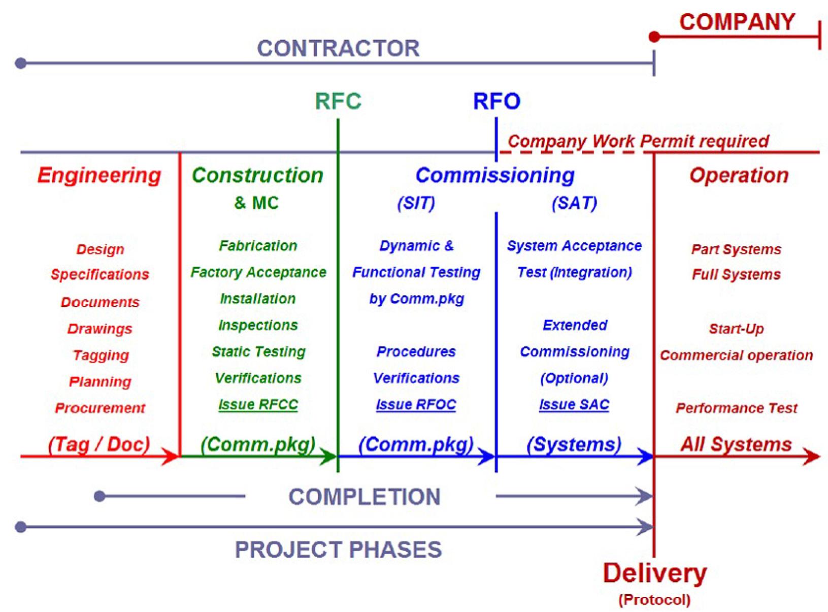
The Concrete factories
Advertisement
Acciona Ghella Joint Venture (AGJV) assembled three precast factories to produce the precast rings, to feed the 4 hard rock TBMs; the first factory had its start-up in May 2016 and the third in September the same year. The precast rings were made of 7 pieces (6 segments + 1 key segment) and one invert segment. The concrete strength of the segments is 55 MPa.
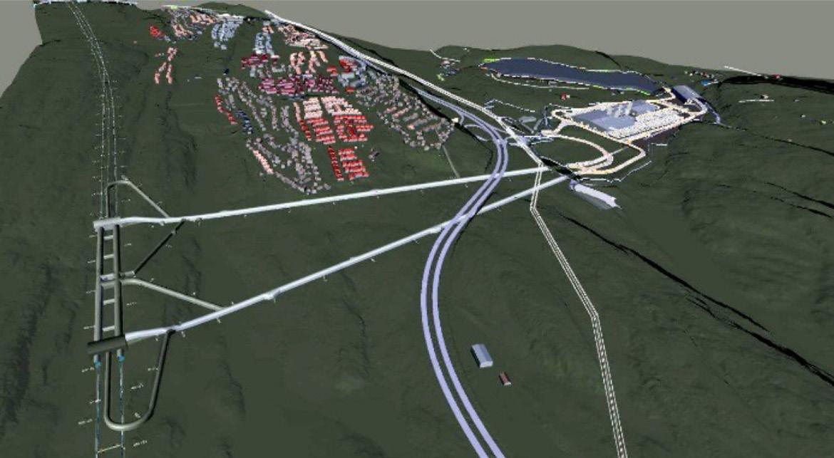
The factories were placed in the upper area, close to the spoil shed, as the first intention was to reuse the material coming from the excavation of the TBMs to produce the aggregates for the concrete production. In this way, both the spoil shed, crushing plant, aggregate shed and precast factories were located in the same area. Layout was focused on re-use of the spoil from the excavation, area constrains and optimization. The area available for all the activities related to the tunnel excavation, including deposit of 9 million tons of spoil and production of the lining for the 20 km long twin-tube, constrained challenged not only for the layout design, but also for the running day by day activity.
Around 20.000 precast rings were produced in the project; this required more than 460.000m3 of concrete and 18.000 tons of structural steel. This led to the biggest cement contract ever awarded in Norway.
In regular conditions, one precast segment was produced in Follo Line every 5,6 min.
Figure 16-1: The spoil shed, crushing plant, aggregate shed, batching plant and the factories.
The material from the TBM´s was planned to be used for the production of the segments, and the entire production was organized in order to fulfil this intention. The excavated material was transported by a conveyor belt system from each of the TBMs.
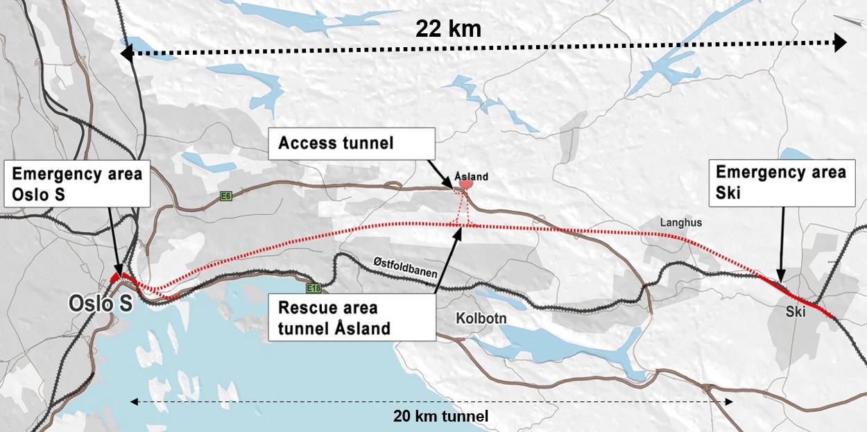
These tunnel conveyors, C1, C2, C3 and C4, unloaded the spoil on two cross conveyors (named CT-N and CT-S) placed in the central cross passage of the rescue area tunnels. Tunnel conveyors C1, C2, C3 and C4 had a capacity of 1000t/h (belt width: 1000mm), designed for a TBM advance speed of 80mm/min. The rest of the conveyors (inside the rescue tunnels, adit tunnels, and overland conveyors had a capacity of 2400t/h each (belt width: 2400mm).
The excavated material was transported by conveyor belts to the spoil shed, which was located approximately 500 meters from the tunnel portals. From
the conveyor belt, the material was dropped into the spoil shed and from there delivered to the crushing plant, where the aggregates were produced and stored in the aggregates store. From this place, the aggregates were transported to the batching plants by a conveyor system.
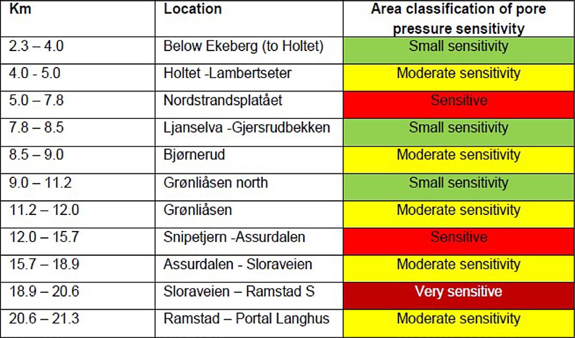
Shortly after the start-up of the aggregate production, presence of pyrrhotite in the material was discovered. In some of the samples, the content of pyrrhotite was too high to be used for concrete production. It was not a clear picture of where pyrrhotite was present or not, so massive and continuous testing was needed to sort out the material which was pyrrhotite-free. The production line was not prepared for such massive testing, so it was decided to stop the crushing of the excavated material for aggregate production. Instead, commercial pyrrhotite-free aggregates were used for the concrete production. This is described in more detail in chapter 9 “Use of the tunnel spoil”.

Figure 16-2: 3D-illustration of the spoil shed, crushing plan, aggregate shed, batching plants and factories.
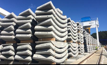
The segmental rings
The detail geometry of the rings is shown in table 16-1 below:
Internal ring diameter 8750 mm
Segment geometry Universal ring with parallelogram segments and trapezoidal key
Segment length 1800 mm (nominal)
Segment thickness 400 mm
Segment taper 40 mm at trailing edge
Table 16-1: Geometry of the segmental rings.
Segment accessories
Each ring consists of the following segment accessories:
• Dowels – 19 per ring in normal rings • Fama dowels – 38 per ring in X rings • Spear bolts – 14 per ring • Guide rods – 7 per ring • Packers – 38 per ring • Gasket – 1 anchor gasket per segment; The water tightness of the gasket was tested and verified for the design pressure of 33 bar at the theoretical gap, with an additional 5 mm tolerance to account for evenness imperfections and installation tolerances.
It´s relevant to mention that the segments were designed without bolts between adjacent rings.
Segment Recess
Each ring consists of the following quantity of segment recesses:
• Grout sockets – 7 per ring • T20 sockets – 19 per ring • Vacuum lift sockets – 14 per ring. Inside the factories, each one had 2 gantry cranes, the first one to demold the segments, the second one to move the segments in to the pre-storage area.
Space constrains also stressed the need of good lay out when it came to rebar preparation.
Logistic and equipment
There were three independent factories, each one with its own carousel system and a batching plant. As described in Chapter 12, “Infrastructure, logistic and the TBM boring process”, AGJV reduced after contract award the number of factories from 4 to 3. Due to the special weather conditions, the batching plants, aggregate shed, and factories were covered. There were also two factories where the reinforcement cages were assembled. They arrived preassembled from Germany, and on site they were welded in a template until the final form. There were different types of reinforcement cages in correspondence of the position of the ring in the tunnel (overburden and distance from the portal)
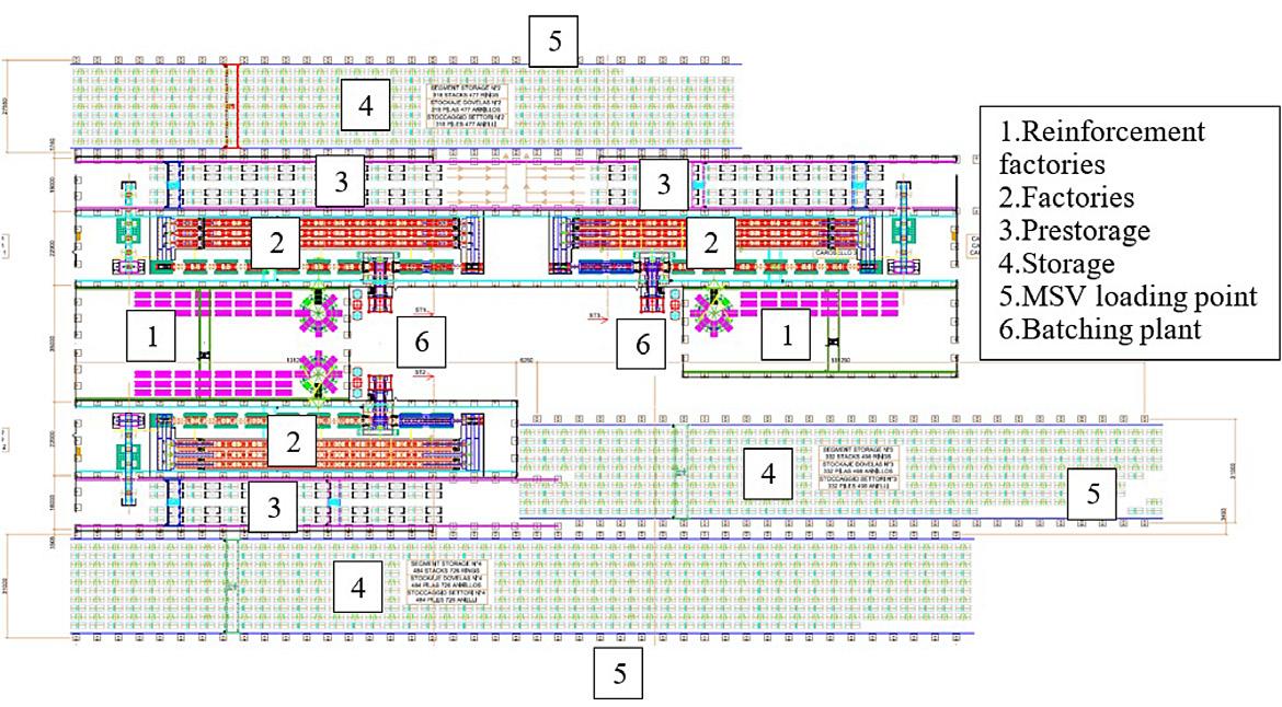
Figure 16-3: Segment factories layout including batching plants and storage- and loading areas.
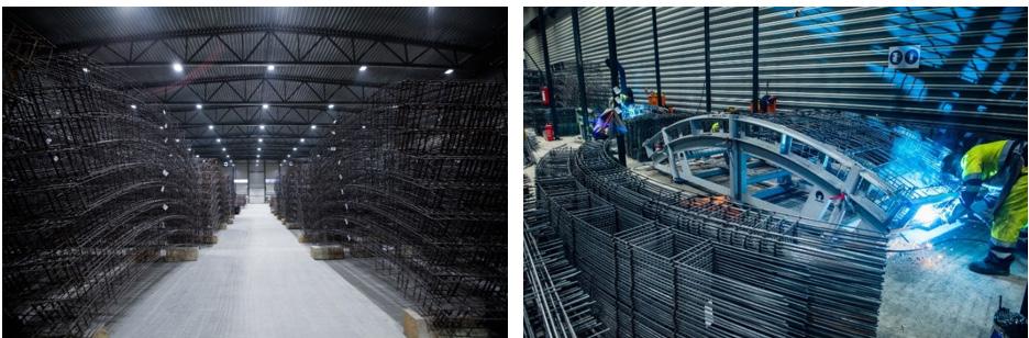
Figure 16-4: Reinforcement factory where welding of reinforcement cages took place.

Figure 16-5: One of the storage areas with the gantry crane.
Two extra gantry cranes were installed in the reinforcement factories to handle the steel cages.
The storage area for the segments were split in three different areas around the factories. Each area had their own gantry crane. With this crane, the segments were moved from the pre-storage area, inside the factory, to the storage area, and from the storage area to the Multi service vehicle (MSV) to be transported into the tunnel. The crane was equipped with a clamp, able to lift 4 segments at the same time. In this way, one complete ring could be moved in two movements. The mixers of the batching plant had a capacity of 2m3 per batch.
More than 200 workers were involved in the precast production during the period when all the three factories were in operation. The activities related to production and loading of segments for supporting the four TBMs took place around the clock. In total, more than 1 million working hours were performed during approximately 2 ½ years of production. During this period, there were no serious accidents, although the high number of hours worked, and the risk activities like the lifting of each of the 161.000 segments, which happened minimum four times per piece (de-molding, pre-storage, storage, and loading).
The manufacturing of segments
Each factory had a total of 48 molds to complete 6 precast rings. The distribution of the molds could be split in two areas, the working line, and the curing chamber. The pieces were produced with high precision and the tolerance of the molds was checked regularly. The tolerance was ±1mm in the diagonal measurements and less than 0,5mm in the other dimensions.

Figure 16-6: The production line (carousel) in each of the factories.
The working line had 10 positions in total, in the first one, the mold with the segment had just come out from the curing chamber and the mold was opened. The segments were de-molded/ lifted up from the mold with a vacuum clamp.
Then the mold was cleaned, oiled and gaskets installed. In the reinforcement station, the steel cage was installed inside the mold and the mold was closed. In this point, everything was ready to start the casting. This pouring was done in the concrete station. There the batching plant operator produced the concrete and coordinated the activity with the carousel operator. From this position, all the workflows were coordinated, and it was only the carousel operator who could move the carousel. To do that,
the different positions in the working line had to approve the movement by pressing a button when they have finished their activity.
The concrete to produce the segments, had a slump requirement between 10 and 40 mm to be able to reach the strength in a short time. In order to fill the mold completely, surface vibrators were needed in the mold in addition to a high pressure of around 8 bar.
Each ring was produced in around 50 min, this performance was possible due to the curing chamber. Here, the concrete was cured with the proper temperature and humidity conditions to be hard enough for de-molding around 5 hours after the casting.
The concrete temperature was also important to get this early strength. This temperature should be around 20ºC. To reach it, in wintertime, the concrete was produced with hot water and warm aggregates. To achieve this, a boiler system was implanted in the batching plants.
When the segment left the curing chamber, the mold was opened, and the segment was de-molded with a vacuum clamp. This vacuum clamp transported the segment to a turning device, where the

Figure 16-7: The carousel working line; Cleaned molds.
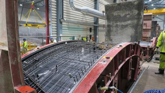
Figure 16-8: The carousel working line; Reinforcement station. Figure 16-9: The carousel working line; Concrete cabin.
Figure 16-10: The carousel working line; Finishing the upper surface of the segment.
Figure 16-11: The carousel working line; Segment going into the curing chamber.

segment turned to its final position. In this position the segment was transported into the pre-storage area though the evacuation line. Here the operators evaluated the segments and performed repair in case that was needed.
Once the segment was casted, the mold was opened again in order to properly finish the upper surface in the mold. After that, the mold was closed again and was sent into the curing chamber.


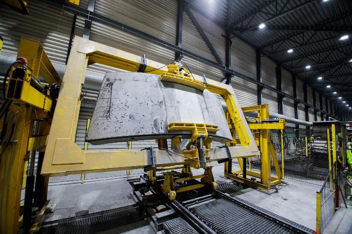
Figure 16-12: The carousel working line: De-molding station. Figure 16-13: The carousel working line; Turing the segment around for “storage position”.
Due to the special conditions during the wintertime, with temperatures below -10ºC, in combination with the temperatures of around 45ºC in the segments when they left the curing chamber, special mitigations were implemented to avoid thermal shocks in the concrete. This could affect the strength development and thermal stress cracks could occur. An indoor pre-storage area was designed in each

Figure 16-14: The carousel working line; Inspection, clarification or repair station.
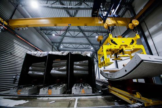
Figure 16-15: The carousel working line; Indoor pre-storage of the segments. factory. This area had capacity enough to keep the segments around 2 days before they left the factory building.
In this point, the segments were already stored in packages of 4 segments, so the external storage crane could handle them in packages of half rings.
The installation of the segmental lining
The segments were transported to the tunnel and further down to the TBMs in a multi service vehicle (MSV), which was able to transport two complete rings at the same time, dealing as well with thigh curves and significant slopes.
The segments were sequenced from segment A to segment B1, B2, B3, B4, B5 and the key (K), which was also the construction sequence for the complete ring. Before the segment installation of the ring, the excavation and the re-gripping were be done.

Figure 16-16: Transportation of the segments from the storage area to the TBMs.
The complete procedure of ring build included the following steps:
• Unloading of the MSV in the TBM backup • Segments were transferred to ring building area by the segment crane and feeder • Ring position selection • Ring erection
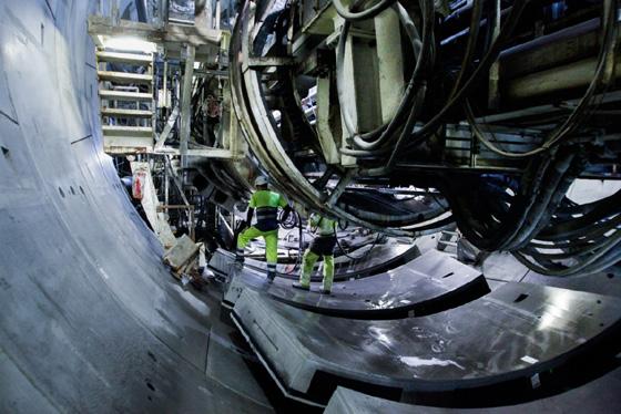
Figure 16-17: Feeding segments in the right sequence.
Figure 16-18: The cylinders at the TBM pushed against the segments during the installation.
Figure 16-19: Crane operator maneuverings the segments in the right position. The segment crane operator operated the crane and placed the segments on the feeder in a direction so that the front edges of the segments were facing the TBM, and the trailing edge of the segments were facing the portal.


The ring selection process took place after re-gripping was completed and before the next ring should be built. The precast segmental lining was designed in such way to allow 19 different positions to be built. The rings were “universal rings” which meant that the tendency of the ring alignment was solely based on the ring position, and there was not a left- or righthand ring option.
Each segment was erected in the sequence A, B1, B2, B3, B4, B5 and K (key segment).
The erector operator picked up the A segment with the vacuum plate and controlled the segment into the desired location according to the confirmed ring selection. The installed dowel on the segment should be precisely aligned with the dowel socket on the front edge, and the steps at the circumferential joint should be flushed with the previously built ring.
After the segment position was confirmed, the erector operator controlled the ram to extend and push the A segment into the final position. A similar method applied to installation of the B1 segment; the erector operator controlled the B1 segment to ensure that the guide rod groove on B1 segment fitted on the guide rod installed on A and pushed the B1 segment into the final position.
The same methodology applied from B2 to B5 and K.
Spear bolts were inserted at the radial joints by the segment installers after the final installation of the ring.
Filling of the annular gap between the ring and the rock surface – Backfilling
In order to provide stability of the precast ring, the space between excavated rock surface and the outer part of the ring (annulus) had to be filled. This was carried out as described below.
The primary annular filling injection was performed from eight double lines through the tail shield. This operation allowed filling of the lower part of the annulus.
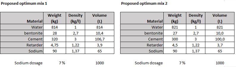
The mix design per batch of component A was a mix between cement, bentonite, retarder, and water.
The upper part was filled in secondary filling stage.
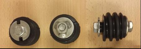
One grout socket was embedded in each segment. The grout sockets were caped before the extrados of the segment. Before injection through the segment the cap of the grout sockets had to be drilled through with an approximate 25 mm drill bits. The non-return valve was installed to prevent grout back flow after injection, and it was fitted in the grout socket after penetrated the segment and before starting of grout injection.

Figure 16-20: Grout socket in the segment (middle).
Bi-component grout should completely seal the grout socket at the completion of each segment injection. This was achieved by avoiding flushing of the lines with component A through the grout socket before removing the injection packer. A three-way valve was introduced just before the segment injection packer, so when the injection was finished and the pressure had been reached, the three-way valve was switched so that the bi-component flow was re-directed towards the flushing line. By this procedure, the grout socket was filled with compacted bi-component grout and ensured a complete seal of the grout socket. The grout operator then switched off the component B pump so that component A ran through the mixing nozzle and flushing lines for around 5 L. Refer to illustration below.
The key of batching the grout at the mixer on surface was to ensure that the material mixed in the mixer was following the mix design.
To achieve the right mix design, the weight of the raw material such as cement, bentonite, water, and retarder to be discharged to mixer was adjusted at the grout plant control panel.

Figure 16-21: An illustration of how the grout nozzle were set up.

Figure 16-22: The bi-component plant located at the rig area outside the tunnel portal. Figure 16-23: Secondary grouting through grout ports.
Transfer of Component A and B to the staging tank on the TBMs
The backfill grouting system was auto mode, which meant that the grout plant on the surface was synchronized with the grout injection system on the four TBMs. The component A and B pump on the surface was automatically activated and transferring the components from the bi-component plant on the surface to their staging tanks on TBMs gantries until the upper threshold of the staging tank was reached. The surface pumps could also be operating manually from the surface control panel. But this was limited for exceptional cases.
The backfilling concept
The backfill grouting concept was to complete primary grouting cycles with injection through the shield for the lower 265 degree of the tunnel annulus. Followed by completing the secondary backfilling of remaining top 95 degree of tunnel annulus through the grout ports of the segments. This concept had the following benefits:
• Injection through the shield minimized the possibility of breaking the segment behind the grout ports • Reduced amount of pressurized backfill material in the tunnel crown to lower leaking of bicomponent grout into the TBM system • Minimize pressure on spring plate reduced the delay related grouting contaminating the grippers.
Primary grouting It was crucial to provide immediate support at the invert of the ring whenever the built ring became suspended from the tailskin. The primary grouting should start when the tailskin moved forward and forming a 300mm clearance between the spring plate and previous grout. The grout flew from all injection ports except the two lines at the top of the tail skin forming a support to the ring of 265 degrees. In double shield mode, the tailskin moved forward by retracting the main thrust cylinder and extension of auxiliary thrust cylinders during “regripping” process. In single shield mode, the tailskin moved forward extending only the auxiliary cylinders as the machine advances.
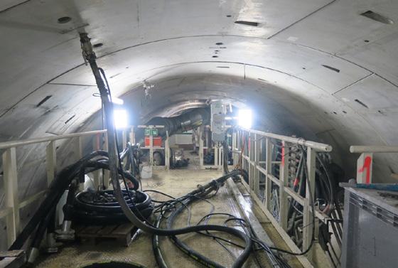
Secondary grouting The injection of the remaining 95 degrees was executed with the secondary grouting through the segments at specific grout socket injection locations. The injection took place from the mobile platform at the top deck of the bridge or from the stairs that connected the top deck to the middle deck.
The injections were performed approximate 6 rings behind the last installed ring using special injection nozzles, as illustrated in figure 16-20 and 16-21 above and in figure 16-23 below.
Bi-component mix for the secondary grouting For the secondary grouting, the component A mix was the same as used for the primary grouting by the tailskin injection. The dosage of Sodium silicate for the B-component was different. The final mix had a higher gel time, in order to be able to inject two or more rings in one time. This dosage difference had an impact on the short-term strength, but as this was an injection for the top part only, it did not need this early strength to sustain the ring. The mix had a dosage of component B at approximate 6%. Gel time was assessed during grout trials and dosage could be changed accordingly.