8 minute read
8 Dust- and water treatment

from Tunnelling in the Follo Line Project - NFF Norwegian Tunnelling Society publication no 29
by TunnelTalk

Jostein Kjørstad, Acciona Ghella Joint Venture (AGJV)
Dust emission
Advertisement
Introduction
Transport and handling of TBM spoil on the surface had potential to cause dust emissions on site that might disturb both site operations and residential neighbours. Dust has been kept under control by three main measures:
Sealed spoil conveyor with watering system
TBM spoil was transported out of the tunnel in a closed conveyor system (refer to Installations and Logistics), with an inbuilt watering system. The watering system limited the amount of dust generated by the spoil, and the closed conveyor ensured no dust was emitted during internal transport.
During depositing the spoil in the internal deposit area, dust was primarily managed by ensuring the moisture level of the spoil was sufficiently high to prevent dust generation from occurring. Dust binding chemicals and water spray was used on temporary transit roads as required.
Dust binding on roads
The main internal roads were asphalted, and most of the production area surfaces were sealed. In addition, a chemical dust binder (magnesium chloride) was applied on internal roads to limit dust mobilisation by truck traffic. These measures ensured that dust generation was limited to a minimum.
Figure 8-1: Sealed spoil conveyor under construction.
Dust monitoring
Dust generation was a daily check list item in the environmental management plan, and environmental officers together with logistics department operators would respond quickly to any visible dust clouds arising.
A dust monitoring station was installed at the end of the deposit area, close to several neighbours. Dust samples were collected over the course of a month and analysed at an external laboratory. The results showed that emissions were generally low, and always far below the permissible level in the pollution permit for the project (“Tillatelse etter forurensningsloven for anleggsarbeider ved bygging av Follobanen mellom Oslo S og Ski stasjon”, Fylkesmannen i Oslo og Akershus, 2015).

Figure 8-2: Dust monitoring results.
Tunnel water treatment
The project’s pollution permit stipulated that all tunnel water was to be treated and discharged to the municipal sewage network (Oslo VAV). The permit required continuous monitoring, flow proportional sampling, online monitoring access and weekly reporting of water quality parameters, such as pH, TSS, oil, nitrogen and heavy metals.

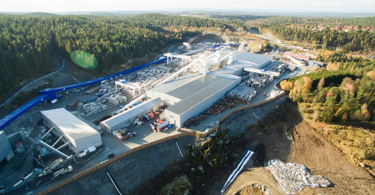
Figure 8-3: Water treatment plant under construction. In order to both comply with these requirements, and to recirculate as much water as possible, the project established a large, advanced water treatment plant (WTP). Tunnel water from all 4 tunnels was collected in a detention basin in the caverns and pumped to the WTP outside the adit portals. The WTP consisted of buffer tank, decanter and filter press, pH control tanks, coalescence separator, quartz filters, and activated carbon filters. In addition, there were large industrial water storage tanks for treated water, and an emergency basin.
The WTP had a capacity of 60L/s (216m3/hr), and it treated water at incoming water quality of Total Suspended Solids (TSS) 10-20 000mg/l and pH 12-13, to clean water with TSS <20mg/l and pH 9. The WTP initially used hydrochloric and sulphuric acid for pH reduction, but in order to operate more efficiently, switched to CO2, which proved highly effective The WTP was operational 24/7 for the duration of the project, with a permanent fulltime operator.
Typically, in tunnel projects, the main water quality issues are related to pH and TSS. None of these parameters have caused problems in this project, because of the water treatment process.

Figure 8-4: pH and TSS before and after WTP process.
Furthermore, nitrogen, which is often one of the main contaminants of concern in tunnelling, has not been a problem in this project, mainly due to the use of TBM (compared to drill and blast).
However, the water treatment was not without challenges:
• Unbalanced incoming flow - In the early stage of the TBM-drilling, there was limited balancing capacity for the raw water in the tunnel. This resulted in irregular flow into the WTP, which caused operational challenges such as overflows and clogging due to mud build-up in the decanter in the WTP. Overflows were collected in the internal containment system, but the this caused a very high workload for WTP operators. - Two parallel detention basins and double pump sumps were built in adit north, which run on 12 hours rotation. Mud build-up in the basins was removed daily by an internal sucker truck and transported to the WTP on the surface. - An additional filter press was built to support WTP1, which increased the capacity by 150% from September 2017.
• Treatment capacity - To handle the total amount of water more than 60 l/s in the tunnel, the capacity of the water treatment plant had to be increased. - A second water treatment plant (WTP2) was built in similar style to WTP1, with 30 l/s capacity. WTP2 was operational from May 2018. Combined capacity of WTP1+WTP2 was then 90 l/s - While WTP2 was being built, contractor installed a temporary WTP in traditional style - using 6 sedimentation containers and acid pH adjustment, which was used to support WTP1 during periods of extraordinary high inflow from December 2017 to April 2018. • Discharge volume restrictions - Nearly 50% of the treated water from the WTP was sent to industrial water tanks for reuse in TBMs and on the surface. The remaining water was discharged to the municipal sewer system (VAV) under the environmental permits for the project. The VAV pipeline had a volume restriction of 25 l/s (later increased to 40 l/s) due to pipe size limitations downstream. - This meant that the WTP operators had to restrict the discharge rate, and carefully balance the treated water to avoid exceeding the discharge capacity.
• pH adjustment - The incoming water was highly basic, with pH in the range of 12-13 - Initially, pH was controlled with sulphuric acid. This increased sulphate concentrations and caused difficulties in complying with the discharge limit for sulphate. - Then, the WTP switched to a combination of hydrochloric and sulphuric acid in order to limit sulphate concentrations. High consumption of hydrochloric acid, however, caused corrosion of WTP and uncomfortable working conditions. - Finally, a CO2 system was installed for controlling pH. This worked efficiently without any significant drawbacks.
• Hexavalent chromium:
Soon after start-up of the TBMs (TBM1 Queen
Eufemia started up 05/09/2016, and by
December 2016, all 4 TBMs were running), we observed a clear increase in chromium concentrations in the treated tunnel wastewater, from approximately 20 μg/l to 150 μg/l.

Figure 8-5: Chromium levels before and after start-up of the TBMs.
An extensive sampling program was implemented to determine the source of the chromium. It concluded that it originates from the various cement products used in the tunnel (mortar for segments, and pre-grouting), and from the concrete element production. As the water volume from the tunnel was significantly higher than from other sources into the WTP, the cement use in the tunnel was considered as the main source.
Furthermore, it was found that nearly all the available chromium in the water was hexavalent chromium CrVI, as shown in the figure below.

Figure 8-6: Source sampling chromium.
After a series of original research and development work, which included cooperation with consulting, industry and technology experts, AGJV developed several methods for reducing chromium concentrations in the wastewater. With the assistance of Acciona Aqua and Centre for Research and Innovation in Madrid, three alternative methods were tested in laboratory conditions: electrocoagulation, active carbon, and iron sulphate addition. The chosen solution was robust enough to handle large variations in water quality and could be implemented in the current WTP without interfering with the 24/7 operation.
By adding iron sulphate heptahydrate FeSO4 7H2O, water soluble hexavalent chromium was reduced to trivalent chromium, and settled out together with the other particles in the wastewater.

Figure 8-7: Chemical formula for hexavalent chromium reduction in alkaline and acidic conditions.
Figure 8-8: Iron sulphate dosing unit installed in water treatment plant.
The method can be described as follows:
• Dosing tank and pump • Mixing tank (1500 l), for mixing iron sulphate heptahydrate with clean water • Addition of iron sulphate mix to wastewater decanter tank (40 m3), together with flocculating polymer, settling out 80-90% of the chromium • The method is proven to work at pH 10-13, and should theoretically work in acidic conditions as well • Dosing ratio dependent on water quality, approx. 0,1-0,3 kg/m3 wastewater • Reaction-time <20 minutes

Compared to the total amount of solids, the amount of chromium was so low that it did not affect the contamination level of the dewatered sludge (filter cakes).
As shown in the below graph, which compares wastewater treated with and without FeSO4 treatment, the FeSO4 treatment achieved an 80% reduction.
Chromium level in incoming wastewater varied over time, depending on groundwater intrusion in the tunnels, amounts of pre-grouting, and parallel work activities. There is no direct link to TBM as a driving method. Cement works combined with high water flows lead to elevated chromium levels.
As with all water treatment systems, and any type of recipe, dedicated operators and continued attention is essential for optimal result. While the principles of water management remain the same; project, site, and personnel specific factors will have a significant impact on the success of any water management system. Thanks to the resources assigned to this issue and the dedicated project personnel, AGJV managed to resolve this issue successfully.

Figure 8-9: Comparison treatment with and without FeSO4.