26 minute read
6. Safety and working environment during the construction phase

from Tunnelling in the Follo Line Project - NFF Norwegian Tunnelling Society publication no 29
by TunnelTalk

Francisco Javier Cuenca Bravo, Acciona Ghella Joint Venture (AGJV) Geir Elvemo, Bane NOR
OH&S Objectives and Policy
Advertisement
The EPC TBM Follo Line project’s objective and policy was to strive for the achievement in obtaining zero harm to everyone and everything both internally and externally. The policy served as a guideline and foundation of the OH&S work and was mandatory to be followed by all. The performance of the project should at all time guaranty the safety for all personnel, both internal and external, including the communities surrounding the project.
AGJV defined the following objectives for the project to support the vision of zero harm, covering both active and proactive objectives and targets:
• Provide a safe working environment that resulted in no injuries • At all time, work towards having zero incidents. • Aim for parent client’s Commitment (Zero
Harm). • Facilitate and maintain effective communication regarding health and safety between all stakeholders in the project. • Provide a workplace environment in which all employees could consult and participate in matters relating to project health and safety. • Encourage to report all accidents/incidents and near misses. • Reward safety. • Give high priority to safety, in order to protect life, health, property and environment. • Deliver compliance with the laws of Norway, internal and international standards, in addition to requirements from client, supporting Bane
NOR´s vision of zero harm. • Achieve continuous improvement in OH&S performance. • Establish objectives and targets; measure, appraise and report OH&S performance. • Protect the environment and prevent pollution. • Safeguard the interests of neighboring local communities.
Leadership and commitment
AGJV´s Senior management were fully committed to OH&S and adopted a visible leadership role. This policy was developed and enhanced by visible leadership that started at senior management level and cascaded down to supervisor level and included leading by example. Proactive target setting that involved consultation with staff and contractors and was driven by individual and team performance appraisal.
Identification of risk item - The organization and follow-up
The Follo Line project was, during the construction period, the largest transport project in Norway. Workers from 62 different nationalities around the world have contributed to the success and positive progress.
The senior management team was an international team composed of highly skilled and motivated individuals, working towards achieving a unified goal of creating company culture within an international environment.
Multicultural Workshops, OH&S handbook translated to most relevant languages of the project (Polish, Portuguese, Spanish, Italian, English). Bane NOR collaborated subcontractors and their safety representatives used to gather to discuss and identify risks or difficult challenges that potentially poses a danger to the health and safety of the workers.
Induction courses and OH&S training
Training was important, and to ensure that safety was in complains with the superior goals of the project, all workers had to conduct a mandatory safety course. The aim of the course was to highlight and ensure that all personnel was familiar with the hazards associated with the work they were going to do and the mitigating measures and tools they could use. New work environment is always a risk to any worker, hence having training ensured that they understood the risk and what to do in an event of an emergency.
Crew talks
Pre-shift meetings with the teams conducted by the management before the work commenced, was arranged as small awareness meetings as well as a tool for transmitting information related to health and safety. The goal of the crew talk was to allow and ensure that the workers actively took part in the safety work, and to make all workers understand that the mitigation measures and controls were in
place to reduce the risk in the workplace to “as low as reasonably practicable” (ALARP) level.
Safety Time-out
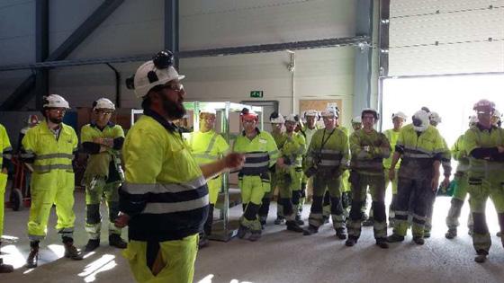
The project involved multiple phases of construction and production activities, all associated with different risks and potential dangers that the workers could be exposed to. During some occasions, the work seemed to be performed without necessary mitigations to prevent accidents. In other occasions, a row of different incidents happened during the execution of the work. To stop such unwanted trends and avoid a serious accident to occur, the line manager arranged Safety time-outs. Then they took a short meeting with the working crew to explain the importance of practicing a good safety attitude during the performance of their work. During this Safety time-outs, the line manager high-lighted specific risks of each task, and informed about near misses with previous activities, in order to enable the workers to understand the importance of conducting their work in a safe manner.
After these Safety time-outs, the frequency of incidents and near misses were reduced, which demonstrated the importance of using this tool, when needed.
Figure 6-1: Safety time-out during the TBM production. Here the Construction Director was in charge of the timeout session.
Figure 6-2: A Tool-box meeting arranged in the precast factory.
Toolbox meeting
Toolbox meetings were arranged as awareness meetings, and they were conducted by all departments. They were managed by AGJV OH&S department by issuing certain topics that the teams should discuss to strengthen the work-site safety and the safety environment of the workforce. The composition of the topics arised either by general concerns, or as specific concerns made by discipline department within AGJV or Bane NOR. In some cases, they were arranged as results of previous incidents.
Safety Rounds
Weekly safety rounds were held to ensure that the work-site safety was complied with and to detect unsafe conditions on site. This unified safety inspection was conducted with both safety- and management representatives from AGJV and Bane NOR, in addition to representatives from the subcontractors.
During the safety rounds, different areas within the construction-site were visited. The safety rounds were always completed with a specific safety-meeting after the inspection. In this meeting, a summary of all the findings from the different areas were given, and actions, in order to improve the safety were discussed and agreed. Other topics related to both safety and environmental issues were also discussed, and relevant actions were identified and agreed. In addition, cases from the previous safetymeetings were followed up.
Safety Observation Cards
AGJV established a system for reporting, analyzing, and follow-up of unsafe conditions and positive observations. Workers could report observations anonymously.
All kinds of findings, which could result in small incidents or serious accidents were reported on special Safety Observation Cards (SOC form) and issued through a deviation system, organized by Bane NOR, called Synergi. As a part of the registrations, actions taken to solve the observations were also registered. All the registrations were followed up in specific weekly meetings between AGJV and Bane NOR.
All the registrations were available for Bane NOR personnel and those who resulted in different kinds of accidents, were reported to the top management of Bane NOR.
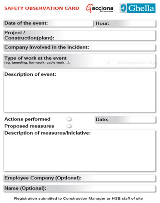
Figure 6-3: Safety Observation Card (SOC).
Corporate change program
To strengthen the safety culture within the organization, AGJV implemented programs aimed to influence and improve safety behaviors of the workforce and the line managers.
Project Leader
The leader program (Proyecto Lidier) is a program aimed at strengthening the leadership through improving behaviors by applying modifications to the work. The purpose by implementing the program, was to ultimately alter the safety attitude by making the safety leadership more visible through direct interaction with the workforce. This also allowed AGJV to transmit their company policies to ensure an implementation of a positive and healthy safety culture throughout the organization. AGJV adopted the program to strengthen the safety culture of the middle management in the project. The program was known as the BBS4YOU-program.

Figure 6-4: Corporate conduct change program.

Figure 6-5: BBS4YOU award ceremony.
The Behavior Based Safety or BBS4YOU program was an application to improve and monitor the workers vision on safety in their daily work. This application contributed and strengthened the safety culture and collective responsibility of the whole workforce in the project. Regularly, the best teams who fulfilled specific requirements related to safety behavior, were nominated, and a winner was awarded a price. The management of both AGJV and Bane NOR took part in the award and gave speeches to honor the winner and highlighted the importance of taking responsibility for always improving the safety at site. The goal for both parties was that all the workers should perform the work every day in a safe way and without being affected by any accident.
5S Methodology
5S is a system for organizing so work can be performed efficiently, effectively, and safely. This system focuses on putting everything where it belongs and keeping the workplace clean, which makes it easier for people to do their jobs without wasting time and / or risking injury. AGJV adopted the 5S methodology to rise the standard on site workshops and construction sites.
Figure 6-6: 5S logo program. Sorting of tools on site workshop. Figure 6-7: Examples of different campaigns arranged at the construction site.


OH&S campaigns
To continue improving and strengthen the safety culture within the organization, AGJV organized safety campaigns during the different project phazes to raise awareness on work site safety.
Safety records
Safety has during the entire construction period been priority number one for Bane NOR. Their organization has, within all levels, had a close cooperation with the contractor, AGJV, in order to prevent serious accidents at the construction site. It has been a goal for both parties that everybody shall return safe and uninjured from work every day.
All near-misses and all kinds of accidents have been reported. The data have been analyzed in order to identify eventual trends or sources for accidents and based on this implement mitigations to avoid new cases to occur.
Both accidents which has resulted in sick leave, defined as H1, as well as accidents where it has been possible to continue to work, H2, has been counted.

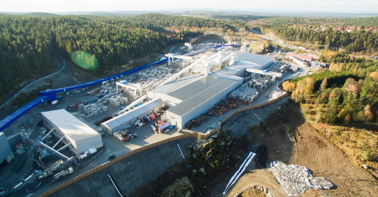
Figure 6-8: Distribution of the different H1-incidents at the Tunnel subproject at the Follo Line project. Figure 6-9: The main access to Åsland construction-site.

In Norway, the following definitions are used as Personal injuries values:
H1; Lost time injury refers for incidents/ accidents pr. 1.000.000 working hours which result in a sick leave
H2; The number of cases pr. 1.000.000 working hours where the employees return to work after sustaining an injury. First aid cases and workers who perform alternative work are also counted within this category.
Personal injuries values for the tunnel part of the Follo Line project counted from June 2015 to end of July 2021 are:
H1: 4,13 and H2: 12,50
As shown in the illustration below, the total number of injuries, which have resulted in sick leave (H1-accidents), represent huge varieties and they are distributed all over the body. The majority of them can be categorized as non-serious
Emergency preparedness
The Follo line EPC TBM project emergency concept was based upon risk analyses, emergency preparedness analyses, and workshop meetings with the Emergency Services.
The emergency plan for the project aimed to respond as fast as possible in a coordinated and efficient way, to minimize the human and material consequences that might have arised from any emergency scenario (work accident, fire, explosion, etc.).
Site Access control system
At Åsland construction-site, the access control system monitored inbound and outbound traffic of both persons and vehicles. In addition, the HSE-card from Norwegian Labour Inspection Authority was used as access card for all employees working at the Åsland construction site. The gate was manned around the clock.
Tunnel Access control system
An integrated tracking system was installed in the tunnel system. The system consisted of personal tags for everybody who should enter the tunnel system and readers installed to monitor areas where the personnel were in the tunnel at any time. It was mandatory for all the workers and visitors to wear a tunnel tag during their stay in the tunnel.
The data was registered in a server and accessible in real time from a computer located in the Tunnel Control Centre (TCC) outside the tunnel.

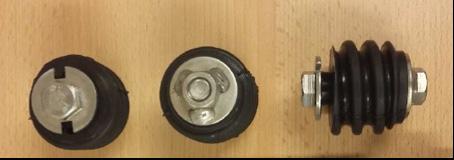
Figure 6-10: Tunnel tag.

Figure 6-11: The Tunnel Control Center (TCC).
The TCC was allocated as command center in case of emergency.
Communication systems
All communication at Åsland site was supported by a redundant optic fiber system. Communication systems in the tunnel was UHF-radios, Wi-Fi and fixed IP-phones, all supported with battery backup. In addition, the national emergency communication system, “Nødnett Tetra”, was used for communication for the Emergency Services.
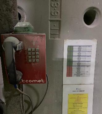
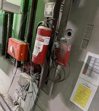
Figure 6-12: Fixed IP phones in TBM tunnel.
Evacuation alarm
Evacuation alarms were installed every 480 m, located near the cross passages. In addition, evacuation alarms were installed in all access tunnels and in the northern interface area close to the Connection to Oslo Central station sub-project. The alarm was visual with a blinking light and equipped with a sound alarm. It was activated and deactivated manually, only from the TCC.
Lighting
Tunnel Illumination levels had an average of 30 lux in walkways and average100 lux in general working areas.
Emergency illumination with backup batteries was installed along the tunnels in a maximum distance of 50m to allow safe exit from the tunnel. The capacity of the batteries were minimum 120 minutes, and this was assumed to be sufficient in order to allow persons in the area to take appropriate action without danger.
Color code to show different installations in the tunnel were established. Fire-fighting equipment were marked with red-lights, and all the exits and emergency points were marked with green lights.

Figure 6-13: Illumination in tunnels.
Hydrant connection points
The water supply from the surface to the tunnels had a total flow rate of min. 17 l/sec at 8 bars to each tunnel. This rate was communicated and agreed with the Emergency Services.
Hydrant connection points with a standard “NOR Lock 1” coupling attached to the industrial water was installed at every 125 m throughout all tunnels as maximum.

Figure 6-14: Hydrant connections in the tunnels marked with red lights.
Emergency points
Emergency or safety points were allocated at every cross passage. The points contained a blinking light and a signal horn for the evacuation alarm, a phone with battery back-up, a first aid kit and 6 kg ABC fire extinguisher.
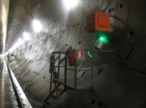
Figure 6-15: Safety point in the tunnels were marked with green lights.
Self-rescuers
Self-rescuers were available for all persons working in and visiting the tunnel. The operation time of the self-rescuer was 60 min with 35 l/min breathing minute volume.
At fixed work locations, as for example cross passages and caverns, the self-rescuers for the whole crew and visitors were stored in fixed special boxes.
On the TBMs, the self-rescuers were stored in a fixed special box located on the TBMs backup.
In the man rider / bus used for transportation of the crew, self-rescuers were stored in special fixed boxes.
All the cars driving into the tunnels were also equipped with the number of self-rescuers corresponding to the number of passengers allowed, including the driver.

Figure 6-16: Self-rescuer storaged in the TBM back up.
Emergency equipment in machinery and equipment
Fire extinguisher (ABC) and first aid kit were mounted in all vehicles. The driver was responsible for the presence of the fire extinguisher in the vehicle. CO2 fire extinguishers were installed at main electrical installations. Each MSV had an automatic and/or a manual fire extinguishing system.
Fire suppression systems on the TBMs
The TBM’s were equipped with automatic “Stat-X” Potassium Carbonate aerosol fire suppression systems.
These systems covered the emergency generator, the hydraulic power pack, the main transformers, and the main electrical cabinets.

Figure 6-17: Emergency sketch for the TBMs.
Development and placement of refuge chambers
Emergency preparedness for the TBM excavation phase was a very crucial period for AGJV and Bane NOR, with very limited evacuation options in terms of fire, smoke and other situations that posed a risk to health and safety of the TBM and tunnel personnel.
As a preventive measure, refuge chambers were used during the tunnel excavation. One chamber was installed on backup 1 of each TBM and on an emergency MSV parked behind each of the 4 TBM’s.
Additional refuge chambers were allocated for works associated with the excavation of cross passages before breakthrough were achieved. They were also allocated during the excavation of the escape tunnel and additional civil works.
The design temperature of all the chambers in case of a fire was 60°C for the full duration of the 28 hours. It was based on the DACH guidelines and so exceeding the requirements of EN16191.
The capacity in the refuge chambers were 24 persons and the operation time was 28 hours.
The refuge chambers were divided into two compartments. One was the airlock and the other was the main compartment where the workers could stay, in case of an emergency situation. This part was equipped with an air filtration system called breathing protection unit or BPU for short, which filtered out all toxic fumes that was brought in from the tunnel. In addition, the refuge chambers also had a cooling chamber to provide fresh circulation of air, a communication system, air measuring devices and first aid kit equipped with wounds treatment, defibrillator, stretcher, eye washer, drinkable water, and meal ready to eat.

Figure 6-18: Refuge chamber at the TBM. Figure 6-19: Gas detector in the refuge chambers.


Figure 6-20: Refuge chamber for cross passages excavation. Figure 6-21: Rescue-vehicle with a refuge chamber.
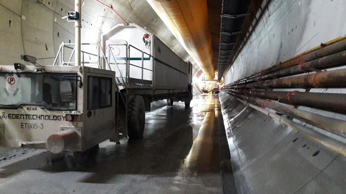


Figure 6-22: Instructions for use and operation of the rescue chamber.

Figure 6-23: the BPU-control panel. Figure 6-24: Control unit for air-cooling.
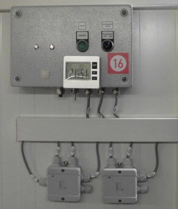

Figure 6-25: Outlet for fresh air.

Figure 6-27: Equipment for communication. Figure 6-26: First aid and fire extinguisher.

All personnel working on the TBMs, including some of the those working in the tunnel, were given an operational training to activate the chamber, but in any case, the activation instructions could be found on the refuge chamber wall close the BPU and was in different languages.
Safe Egress Path
The main concept for evacuation in the Follo Line tunnels was based on the principle of self-evacuation through the smoke free non-incident tunnel.
The cross passages at every 480 m served as egress from the smoke contaminated incident tunnel to the smoke free non-incident tunnel which was the incident free tunnel or the escape tunnel in the first
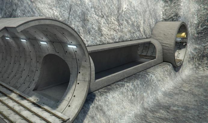
Figure 6-28: Sketch of a cross passages between main tunnels.
The emergency preparedness plan was implemented in the organization through induction courses, training, toolbox talks, exercises, and informative meetings with the Emergency staff. The plan was based on a combination of handing out of instructions and of specific training for those involved in the emergency organization.
With the scope to train and check the status of the ability to handle an emergency for the different key personnel at the Åsland site, Emergency response training was conducted on a regular basis. Tabletop and full-scale exercises were conducted in close cooperation with the Emergency Services, which also gave support during the entire execution of the project.
Emergency Forums on a management level were established at an early stage, to plan and discuss the upcoming activities, possible interferences with adjacent projects and relevant topics related to emergency preparedness.
Training and evacuation exercises were conducted with the Emergency Services related to how to handle incidents in the TBMs and in the rest of the tunnel system.

Figure 6-30: Evacuation exercise with cooperation of public Emergency Service. 2.8 km of the north tunnels. The cross passages were equipped with doors or curtains for air and smoke separation between the tunnels during all construction stages. The length of the cross passages are mainly 25 meters and consists of a free corridor for emergency alongside a space reserved for electrotechnical equipment which were installed during the construction period.
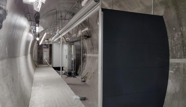
Figure 6-29: Cross passage safety egress.

Figure 6-31: Evacuation exercise on the TBM with cooperation of public Emergency Services.
A design for temporary ventilation system during the TBM section of the Follo Line EPC TBM project was developed.
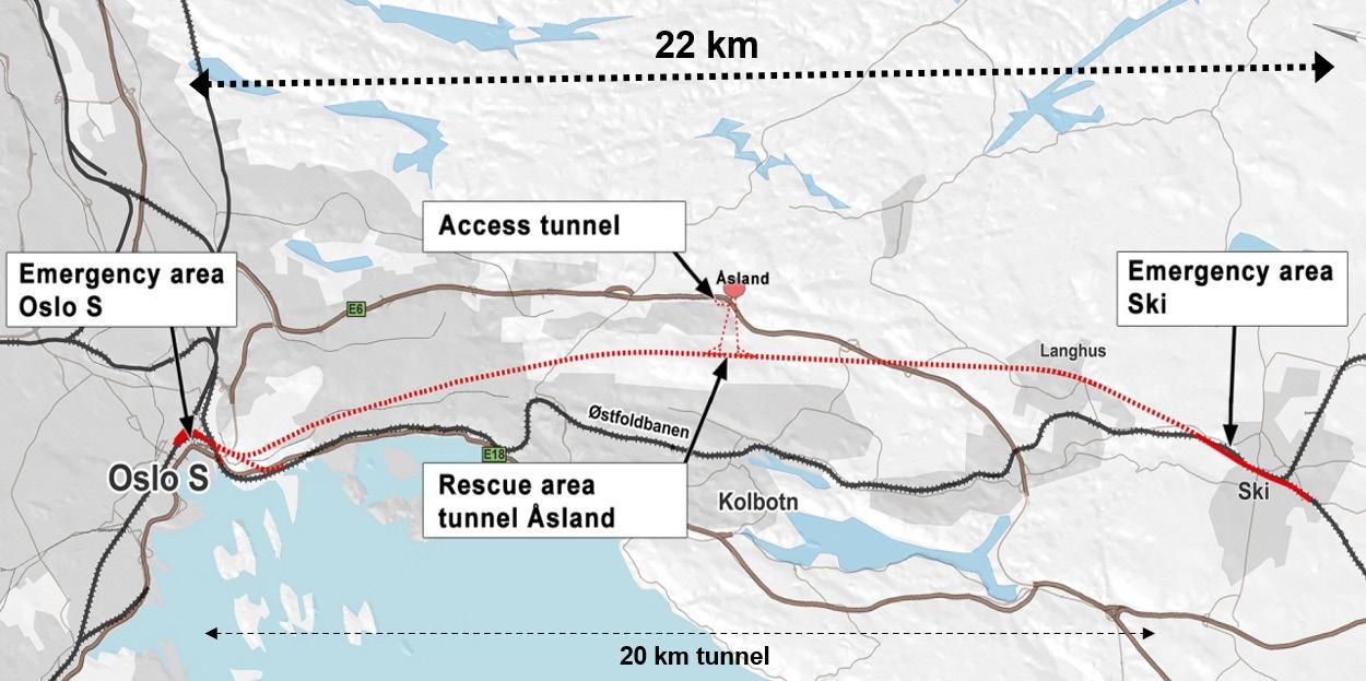
The TBM excavation started in a rescue tunnel midway in the main tunnel. This cavern was accessed from the working site Åsland by two adit tunnels about 1 km long. The entire tunnel system is described in more details in Chapter 19 “Safety concept for the operational phase”. The works required a mechanical ventilation system which ensured the occupational health requirements, fire safety and the technical functionality of the underground installations, both in the heading and the in the adit tunnels. A comprehensive design of this temporary tunnel ventilation system was required in order to cover the varying ventilation needed during the different tunnel construction stages.
Ventilation of Adit, Transport, Auxiliary, Rescue Tunnels and Caverns
The concept of the ventilation of the TBM tunnels was based on circulation maintained by jet fans in the adit tunnels South and North. The air flowed from the Adit South to the Adit North by passing through the rescue tunnels. In order to have minimum contamination of the incoming air, all traffic in Adit South (=air intake) were going downhill with minimum emissions from the vehicles, and all traffic going uphill, including spoil conveyors, were located to Adit North. So that the traffic followed the same “one-way” flow as the airflow.
The fresh-air was blown into each of the four tunnels, where the TBM excavation took place, by large ventilation ducts. The exhausted air was blown from the TBMs, back to the rescue area and then out via Adit North.
After finishing the TBM excavation, the tunnel system had openings in each end. Then, the ventilation system was changed accordingly.
Figure 6-32: Sketch of the ventilation concept after the TBM excavation phase, when connection to other parts of the tunnel system had been established. By curtains in the northern part of the tunnels, the air was directed out via the access tunnel at Sydhavna.


Figure 6-33: Sketch of the ventilation concept Jan/Feb20 when there were free openings in the northern part of the tunnel system.

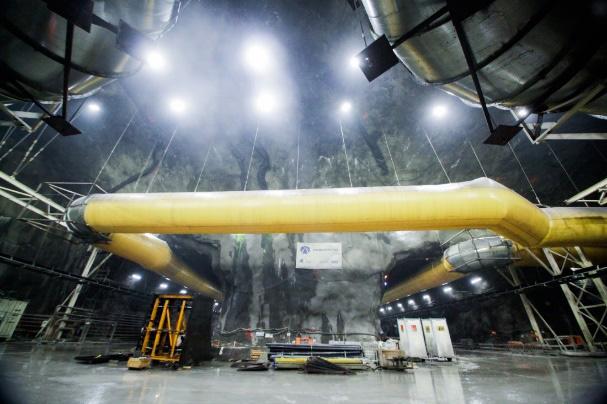
Figure 6-34: Ventilation duct in Rescue area during the TBM excavation. Figure 6-35: Ventilation duct in the assembly chambers.
Ventilation of the Escape Tunnel
The Escape Tunnel, which handle evacuation from the two Follo Line tunnels in the area, where theses tunnels are crossing each other, was excavated by drill & blast. The ventilation system of this Escape Tunnel was completely separated from the Adit ventilation during the excavation phase. Fresh air was supplied to the Escape Tunnel through a ventilation duct by means of a supply fan located on the surface. A fan for blast fume extraction located in the escape tunnel, extracted the blast fumes from the Escape Tunnel, and pushed them through a separate ventilation duct to the surface.
Ventilation of the TBM tunnels
When the TBMs started to operate, the TBM tunnels were ventilated through flexible ducts with a diameter of 2.8 m, located in the crown of the tunnels, which suppled air to the TBM’s. The fans for all four TBM’s were in the Adit extension south and took fresh air coming in through the Adit south.
A large portion of the fresh air arriving at the end of the TBM backup was then moved further forward to the front of the TBM through the fan and ducts of the TBM secondary ventilation. From the front of the TBM, a portion started flowing back through the TBM backup. The other portion of the incom-
ing air was taken in by a separate circuit collecting the dust from the cutter head and from the TBM conveyor discharge area and returned into the main airflow out of the tunnel after passing through a dust scrubber.
Both airflows join within the backup area, and traveled through the tunnel, back to the portals of the TBM tunnels in the assembly caverns together with all leakage flows from the flexible ducting, which also ventilated the whole TBM tunnel.
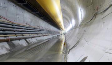
Figure 6-36: Ventilation duct in the TBM tunnels.
Control of ventilation and smoke control in case of a fire
Depending on the location of a fire, the fans had to be operated differently than during normal operation, in order to minimize the smoke-spreading underground, and help the evacuation of the crews. The fans on the TBMs were controlled by the TBM operator and generally switched off under a potential fire. The fans in the Adit-tunnels as well as the main TBM tunnel supply fans were controlled from the Tunnel Control Center (TCC) based on a matrix depending on the exact location of the fire. This matrix was provided as a part of the Fire life Safety report, designed for the project.
The fan control in the TCC should also help the Emergency Services to manage the ventilation in accordance with the required response, depending on the situation.
Bulkheads enabled to control the flow rates in the different branches of the Adit-tunnels and Transport tunnels were installed, following the design ventilation concept.

Figure 6-37: Sketch analyzed Fire scenarios after TBM excavation phase.
Separation of ventilation between parallel TBM tunnels
The main philosophy in the Follo Line tunnels emergency plan was to escape from the tunnels by using the nearest cross passage and then close the emergency door. People entrapped by a fire or toxic atmosphere should use self-rescuer.
In order to ensure that no smoke from one of the TBM tunnels could flow into the parallel tunnel, all cross passages were equipped with temporary bulkheads, which were later replaced with permanent walls and doors. This permanent separation ensured that the second tunnel always remained as a safe place for evacuation. The only time this separation was breached was during blasting works in a cross passage that was already broken through.
In such a case, restrictions to other works (i.e. on the TBM’s) would apply since a safe evacuation path and access for Emergency Services to the TBM could be compromised in case of an emergency.
Is it a health benefit with the TBM method?
The health effect on tunnel workers with TBM method have not been in much focus. Minor studies have been conducted in recent decades, so when the Follo Line project was going to use four TBMs for drilling the tunnels, the National Institute of Occupational health (STAMI) saw an opportunity to
more thoroughly and to a greater extent be able to study what health benefits drilling with TBM could have. Earlier, STAMI had conducted a study in close cooperation with Bane NOR on the Ulrikken-tunnel project in Bergen. This tunnel was excavated by an open TBM. Now they saw the opportunity to do a similar study on a double shield TBM in The Follo Line project. The documentation of the study is included in Appendix I.
Conclusion
The samples taken from the health examinations during the study are still being analyzed and the final results are not presented yet. It is therefore too early to make a final conclusion about the exact health effects drilling with TBM may have compared to excavating tunnels by conventional drill and blast. But for sure, based on the analysis results from the exposure samples that were taken and the actions that were performed through the project to reduce the exposure, a positive effect have been measured. The exposure of dust for the workers who operated close to the cutterhead were reduced.
The test results gathered during drilling with the TBMs showed a difference in dust exposure between different groups depending on where on the TBMs or in the tunnel they worked. The longer away from the cutterhead, the lower the exposure.
The results analyzed so far also demonstrated that drilling with TBM gave significantly less negative dust exposure from diesel exhaust and rock dust than are created from conventional drill and blast excavation. The main reason for this is related to the use of conveyor-belt for the transportation of the excavated material all the way from the TBMs to the surface. This gives less pollution from exhaust from vehicles and less dust whirled up by the wheels.
It is still great opportunities for the industry to reduce the health impact for tunnel workers by focusing on further development of technical solutions and barriers on TBM. It lies a big potential to reduce the negative health effect of dust, by using a larger amount of time on the organizational barriers like mapping dangers, looking at methods for work operations in different groups, i.e., maintenance staff.
Finally; the awareness of each one of the workers, at all levels, knows what they can do to reduce the dust exposure in tunnel work.
References
Ulvestad, B. & Bakke, B. & Melbostad, E. & Fuglerud, P. & Kongerud, J. & Lund, M.B. Increased risk of obstructive pulmonary disease in tunnel workers, Thorax, 2000
Ulvestad, B. & Lund, M.B. & Bakke, B. & Thomassen, Y. & Ellingsen, D.G. Short-term lung function decline in tunnel construction workers, Thorax, 2015