18 minute read
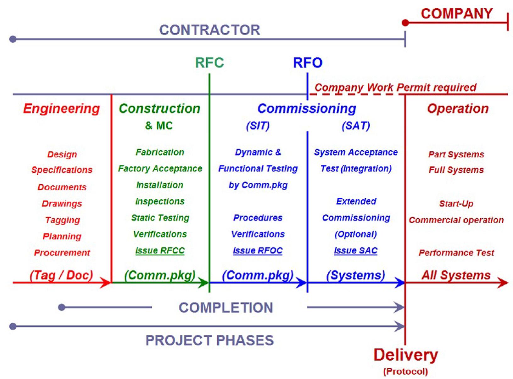
12 Infrastructure, logistic and the TBM boring process

from Tunnelling in the Follo Line Project - NFF Norwegian Tunnelling Society publication no 29
by TunnelTalk

Fernando Vara, Acciona Ghella Joint Venture (AGJV)
Main figures
Advertisement
• 37.000 m TBM tunnel. • 9 M tons of rock • 140.000 concrete segments • 1 M m3 of concrete • 350 km of auxiliary pipes • 1,000 workers - peak • More than 25 nationalities
Site installations and logistic
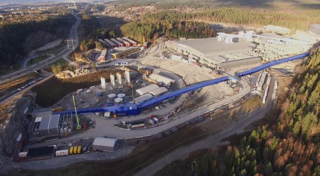
The configuration of the area where the project was settled is an approximately 200,000 m2 of platform, close to the motorway (E6), and it includes the area for the spoil.
The two access tunnels from the rig area down to the future railway tunnels were excavated as prework contract before AGJV started. As part of AGJV scope, it was necessary to excavate additional parts of the access tunnels, transport and auxiliary tunnels and assembly caverns where the machines were going to be assembled. This activity was contemporary with the execution of the civil works for the factories, auxiliary installations, and TBM assembly. The arrangement for the rig area and the tunnel system is illustrated in figure 12-1 below. The first complex task was to define and integrate the whole number of factories and installations that where needed, assuming that the time factor was critical. The contract was signed the 23rd of March 2015, and the land was provided by Bane NOR the 18th of June 2015. The target schedule that AGJV settled, was to start boring with the first TBM by September 2016, and the fourth and last one, by December 2016.
In order to achieve that aggressive schedule, AGJV design team (Acciona Ingenieria was the design company for the Follo Line EPC TBM project) worked very hard on the first 6 months of the project with all different AGJV production teams, until a final compact solution was defined and agreed between all. Finally, four different areas or platforms where established and would include all the factories and auxiliary installations: precast factories, spoil area, portals (lower area) and auxiliary tunnels area. All four areas were linked and integrated from a logistical point of view and the final result was a very compact and efficient industrial/production “city”. A detailed description of those areas will follow in the next sections.
Figure 12-1: A 3D-model of the rig area located close to the main road (E6) and the access tunnel system with the caverns where the TBMs were assembled.
Precast Factories
On top of the challenge of design, procurement, preassembly on factory, disassembly, transport to the site and final assembly on site of the four TBMs, in order to start the excavation of the tunnels with enough time slack, it was needed to have around 2,500 precast concrete rings minimum storage on site before the start-up of the TBMs. Therefore, the precast factories had to be assembled and start the production months well in advance of the TBMs.
After some months of analysis and evaluation of what was designed during the tender process by Acciona and Ghella, and what the new challenges and reality of the area provided, the first critical decision taken was to reduce from four precast factories, as previously agreed, to three.

Figure 12-2: The original design with four precast factories.

Figure 12-3: The new design with three precast factories.
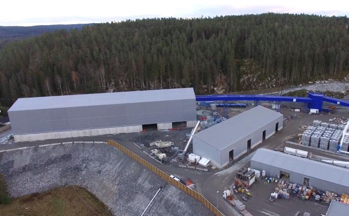
Figure 12-4: The spoil shed (large building) with the conveyor belt (blue) and the building for storage of aggregates (four openings).
That decision was based on an optimization on the area for storage segments. Three factories gave more space for storage. Assuming that with three factories and with time enough for starting the precast rings production in advance, the risk of not having enough rings for the TBMs was controlled for the entire construction period.
Spoil area
The second area that required intensive analysis and different solutions till achievement of the final optimized one, was the spoil shed, where the material excavated from the TBMs was going to be managed, and the crushing plant area for production of aggregates from the excavated rock. The result of the intention of using the crushed spoil as aggregates is described in Chapter 9 “Use of the tunnel spoil”. The spoil area had to be covered to allow working during the winter and during night time. It integrated into the crushing plant area. The final solution was a massive shed covering the spoil, where the conveyor belts were integrated and aligned, and a second shed for the storage of crushed aggregates produced by the crushing plant adjacent to it.
The building for storage of the aggregates were divided in four chambers, each for the different sizes of aggregates needed for the production of segments. Through ports integrated in the floors of the four caverns, the aggregates were dropped down on an underground conveyor best, which brought the aggregates up to the three batching plants for each of the segment factories. The integrated solution included a surrounding wide transit road for dumpers and road trucks, as both would be needed on different stages of the project.
The lower platform
Both the precast and spoil area were placed at level 169. The adit tunnel entrance, where the access to the main tunnels were placed, was at level 150. This difference of levels was another challenge in terms of logistic optimization for the rest of the installations. Final design of the lower level was integrated in the confined space that the excavated portal area created, plus the tunnels access and necessary wide logistical roads. In this area the grouting plants, water treatment plant, substations, workshops, and warehouses were finally allocated.
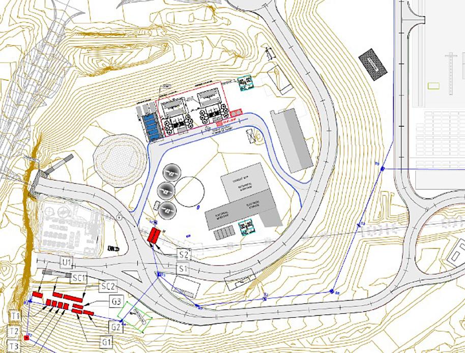
Figure 12-5: Lower area close to the tunnel access portals and installations associated to the tunnels.

Figure 12-6: A 3D-design of one of the auxiliary tunnels, including the tunnel conveyor, ventilation, cables, and pipes. Figure 12-7: Northern cavern with the jacking system used for the assembly of the TBMs Euphemia and Ellisiv.


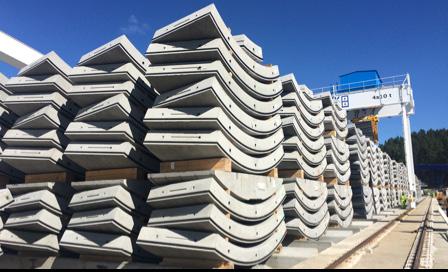
Figure 12-8: Two complete rings storaged close to the precast factory.
Auxiliary tunnels and assembly caverns
The fourth key area of the project were the auxiliary tunnels and assembly caverns. This area had the challenge of combining the intensive traffic that the vehicles getting into the tunnel were producing and the allocation of all tunnel auxiliary installations (ventilation, pipes, electrical cables, and conveyors).
Two assembly caverns located North and South to the adit access tunnels were designed for the

Figure 12-9: Ring geometry and tunnel configuration with the rings.
assembly and launch areas for the TBMs. It had to be big enough and at the same time be integrated into the final permanent tunnel design. Final dimensions of the caverns were 22(H) x 25(W) x 50(L) m.
In each cavern, two TBMs were assembled at the same time. A jacking crane system was selected as the most compacted and polyvalent lifting equipment for that kind of confined space and complex assembly operation.
The integration and coordination of all the equipment installed into the four main areas previously described above, were one of the key elements and success factors for the tunnel excavation on the EPC TBM Follo Line project. In addition, a common “construction green” area, that included offices for both client and contractor (white and blue collars), barracks for 450 workers and a 24/7 canteen, were assembled.
As a final general comment, all the design took into consideration the extreme weather conditions (-25º C) that the site area could suffer during wintertime by installing full covered conveyors, heating cable on asphalt and heated pipes as some examples.
In the following section, a summary of the main equipment and auxiliary plants will be presented.
Precast factories, batching plants, and cranes
AGJV built a large concrete segment factory at the construction site to supply concrete precast elements continuously to the TBMs. The entire area for the three factory is about 20,000 m2 and had three production lines, batching plants, and other auxiliary installations.
Seven concrete segments are needed in order to assemble one complete tunnel ring. The factory produced 20,000 complete rings, or 140,000 concrete elements, in addition to 20,000 invert elements.
Facts about concrete segments (universal ring type): • A complete tunnel ring weight 51.6 tons and consists of seven concrete segments, in addition to one invert segment. • Each ring is 1.8 m wide, 9.55 m high and 40 cm thick. • Each ring consists of 32 parts, including elements, gaskets, and pipes.
Each of the temporary precast factories were assembled on site and included: • 3 carousels: Each carousel included 6 set of 8 moulds. Total 48 moulds (Segment and invert segment) • Power installed and pumps 129 KW • 1 curing chamber 700 KW • Water requirement: 400 l/h
The segmental lining is described in more details in Chapter 16 “Production and installation of the segmental lining”.
For pouring the concrete a set of 3 batching plants were procured and installed integrated with the precast factory.
Main batching plant components: • Model: SIMEN BT 75 • Production: 60 m3/h • Total capacity for storage: 200 m3 for sand storage. • Silos: - 3 units per plant - Dimension: Diameter 3.5 m x Length 8.5 m. - Cement storage capacity silos: 70 m3 (approx. 95 ton) - Silica storage capacity silos: 70 m3 (approx. 50 ton) • Polyaromatic heating units for concrete production under winter conditions (hot water and sand heating).
All the segments, and auxiliary materials inside the factories were lifted by a group of different cranes, as described below: • 3 Segment external storage gantry cranes, 4x10 ton, 30 m span, 185 kW. • 3 De-moulding overhead cranes, 2x8 ton, 21 m span, 25 kW. • 3 Pre-storage overhead cranes, 4x10 ton, 15 m span, 60 kW. • 2 reinforce workshops, overhead cranes, 1x3,2 tons in each ws, 26 m span, 8 kW
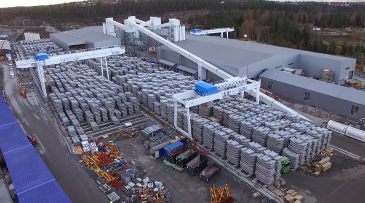
Figure 12-10: The three precast factories and segment storage area.
Crushing plant
During the excavation of the tunnel, between 9 and 10 million tons of rock were excavated. It was the intention to reused 10-15% of the spoil in concrete production, while the rest should be stored near the construction site. Due to the presence of pyrrhotite in some parts of the material, re-use of the spoil as aggregates for the production of concrete was not possible. Reference is made to Chapter 9 “Use of the tunnel spoil”. In the end a very limited amount of aggregates were produced at site. The aggregates were bought from outside instead and stored in the second shed.
The characteristics of the crushing plant were as following: • Groups of crushing and screening Metso for reduction to gravels and sands. • Two shredding groups LT300D and LT7150B, one mobile sieve ST 2.8 and one stationary CVB 202 and a sand treatment group.
The flowchart of this installation was, in summary, planned to be:
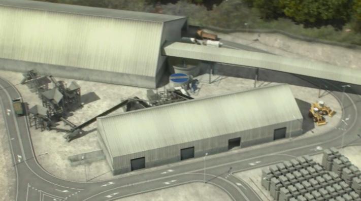
Figure 12-11: A 3D-design of the crushing plant area.
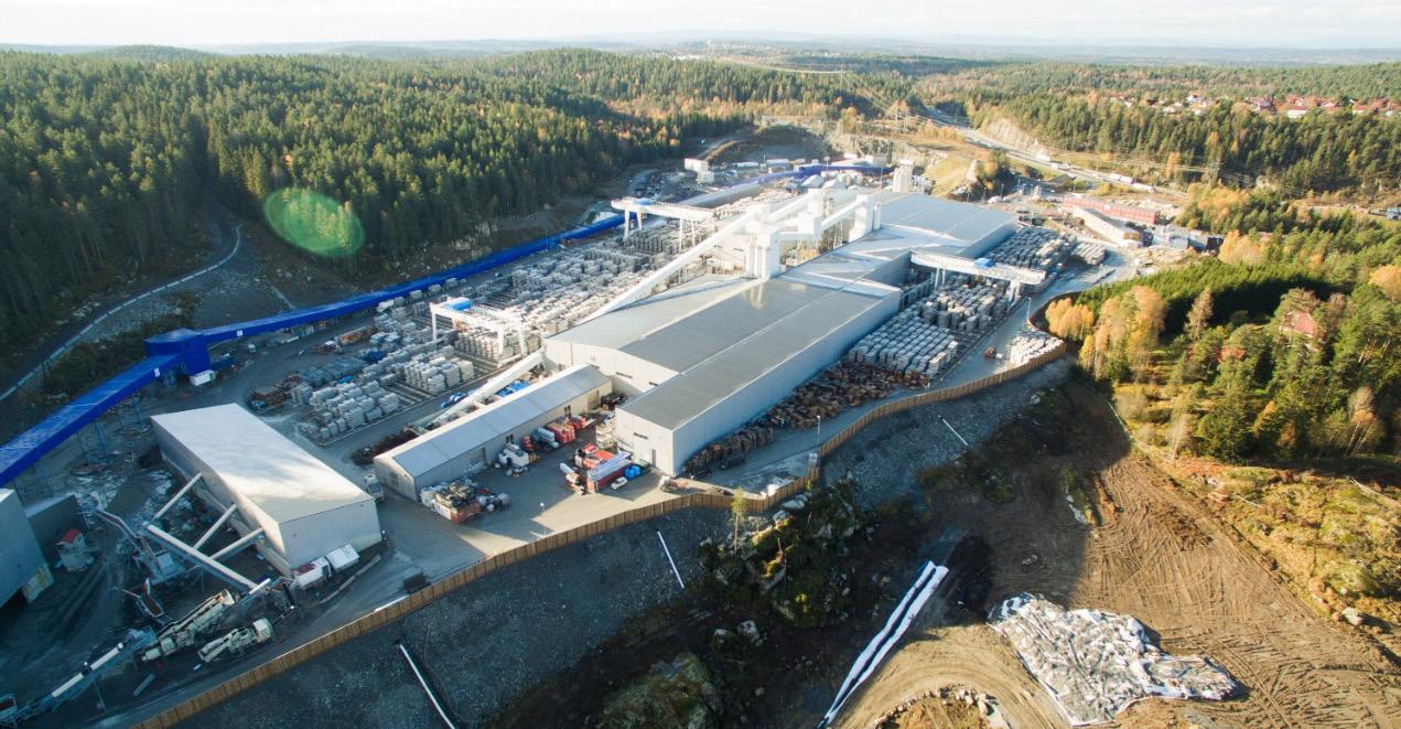
Figure 12-12: An overview of the site. In blue, alignment of the fully covered conveyor belt from the portal of the northern access tunnel towards the spoil area. The feed was 0-100 of granitic rock. This 0-100 undergoes a cleaning process on a ST 2.8 screen, which took advantage of size 20-80mm. This 20-80 was reduced in closed circuit to 0-25mm by means of a cone crusher on tracks, LT330D.
To obtain an excellent coefficient of form, all sizes larger than 6 mm were processed in a vertical axis mill on LT7150B tracks. All 0-25mm already with excellent coefficient of form was classified in a stationary screen CVB 202 with washing to obtain gravel washed 12-25mm and 6-12mm. The resulting 0-6mm were taken to a hydro-cyclone sand treatment group, thickening tank, and filter press to achieve the quality.
Conveyor system
All the material excavated by the TBMs was transported to the spoil shed via a complex conveyor belt system. These conveyors had different sections and belts widths depending on the demand for transport of the full excavation of the four TBMs. The capacity of the conveyors varied from 850 t/h to 2,000 t/h, belt widths from 1,000 mm to 1,200 mm, max. speed of the belt was 3m/s, and the installed power of the head end drive, booster drive and tail end drive went from 945 kW to 315 kW and 250 kW, respectively.
Grouting plant
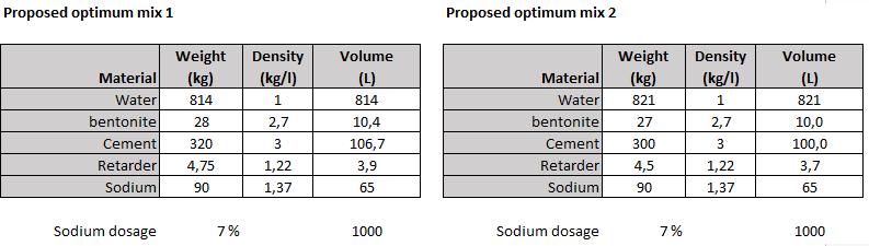
On TBM excavation methodology, it was needed to fill the gap between the external precast ring diameter and the TBM excavation one with mortar. On the Follo Line EPC TBM Project, AGJV choose a bi-component mortar solution. Basically, it was a combination of 2 elements: Component A was a colloidal suspension cement based, with other hydraulic conglomerates, and Component B was an accelerator (sodium silicate). The grouting plants chosen for the mixing and production of the bi-component consisted of two units.
Each Unit Plant consisted of: • 1 Grout Mixer Unit (2 x 20 m³/h) • 6 Vertical Monolithic Silos 85 m³ • 1 Agitator (2 x 6 m³ tanks) • 1 Transfer Pump for A Component (2 x 20 m³/h) • 1 Control Room for the 2 Mixing Plants. • 4 Transfer Pumps for B Component
The auxiliary equipment in the plants handled: • Mixing 2,5 m3, 2,000 l/min, 15 kW • Silicate installations 8 containers of 25 m3 each

Figure 12-13: The grouting plant area.
Water treatment plant
All the water pumped form the caverns to the surface was treated in one of two water treatment plants specifically designed to treat the kind of water that a construction project generates. The contract was very strict in terms of water discharges to the sewage network and water quality levels, so the robustness of the plant was critical. This is described in more detail in Chapter 8, “Dust- and water treatment”
The main characteristics of the each of the water treatment plants were: • Total treatment capacity: 216 m3/h • Wastewater containing on average 15 g/l of TSS • Power installation: 223 kW • Effective working hours: 24 • Oil and grease limit: average 2,000 l/day • pH-limit: 4 to 12 • Buffer and storage tanks for wastewater • Automatic flocculent station • Decanter cylinder tank FB7000V-WDR
The quality limits for the final discharge water were: • pH-limit: 6.5 – 8.5 • Solids contents: 25 mg/l • Oil and grease limit: not visible
Ventilation
Ventilation of the main tunnels and of the auxiliary tunnels was another very complex design solution, as the site configuration was more similar to a mining area in operation.
The final solution included main fans for the TBM tunnels and auxiliary jet fans for the other tunnels.
Main characteristics of the equipment installed:
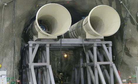
• Main Fans: - Model: ZITRON ZVN 1-20/315-4 - Reversibility: Unidirectional - 4 units in the principal tunnels. - Power: 315 kW - Diameter: 2000 mm - Flow: 68 m3/s • Jet fans: - 24 units in total in the two adit tunnels. - Adit South 7 pairs - Adit North 5 pairs - Power: 41 kW
The fresh air was taken from the rig area and blown through the southern adit tunnel and distributed into the tunnel system from the southern cavern. The northern adit tunnel was used for the exhaust air.
Since the entire tunnel profiles of the southern adit tunnel were used as an air channel, did the cold air during winter time result in many iscycles, which had to be removed manually on a daily basis.
Logistic
Good design in advance, smart ideas, previous experience, and lessons learnt from other similar projects that Acciona and Ghella had been involved in around the world, were the key factor for an achievement of a very compact, robust and 24/7 workable solution.

Figure 12-14: One of the two water treatment plants. Figure 12-15: The main fans in the southern cavern.
But as important as the design of the whole site, the logistic functionality of the day-to-day operations was another key element in this kind of continuous production sites.
The logistic team coordinated the daily internal and external deliveries on site, warehouse, workers’ shifts on barracks and their continuous rotation, among other activities.
The delivery to the TBMs of workers, materials and segments was one of the main activities. AGJV optimized the traffic in the tunnels by the way of using multiservice vehicles (MSVs) instead of the by client originally specified transport by railway. These special transport vehicles allowed to have both ways of traffic into the TBM tunnels with no interruption, as the MSVs were narrower than standard vehicles.
Different types of such special vehicles were procured on the project: men rider (allowed to transport 28 people), segment vehicles (2 complete precast rings could be delivered at the same time) and special platforms for rescue chambers, materials, ventilation, etc. Main characteristics of those vehicles: • MSVs for rings: - 5 units - Model: MSV 130-4-1900 - Power: 405 KW - Service: Each vehicle carried two complete rings - Quadruple Multiservice Vehicle, 8*18*18 - Turning radius: 15 m. - Dimensions: 2100 x 3306 x 43,615 mm - Weight unloaded: 48,000 kg - Max vehicle weight: 172,000 kg - Max speed with load on flat ground = 17 km/h - Max speed with load in maximum slope (10%) = 10 km/h
• MSVs for auxiliary - 11 units - Power: 245 kw - Weight unloaded: 17.000 kg - Max capacity(payload): 21 ton - Crew transport 5 units. 21.x1.981x3.940 mm 18.000 kg - Rescue chamber 4 units. 24.198x1.981x3.940 mm. 18.500 kg - Duct cassette ventilation 2 unit. 23.894x1.981x3.940mm. 18.500 kg
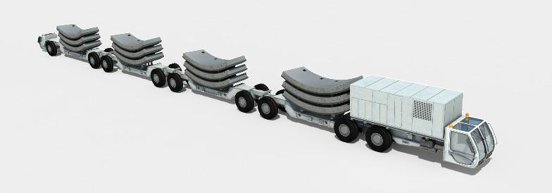
Figure 12-16: Segment MSV – 3D design.
Achieved progress
For the excavation of the 36 km of TBM tunnels, Acciona Ghella Joint Venture procured four brand new double-shell tunnel boring machines (TBMs) from Herrenknecht. The main characteristics of the TBMs were (reference is also made to Chapter 10 “Tailor made TBMs for boring in hard rock at the Follo Line project”): • Adapted to high rock strength. Bane NOR input based on Norwegian experience • 71 Cutter rings 19” on 71 tracks • Heavy structure, stiff support • Diameter machine/internal tunnel diameter: 9.96 m/8.75m • Length of machines: 150 m • Weight: 2,400 tons • Installed Power: 6,200 kW. • Main bearing size increased form 6.0 m to ø 6.6 m
The TBMs were designed, manufactured, pre-assembled and commissioned in Herrenknecht facilities at Schwanau, Germany, previously to their transport to the job site. This works took one year for the 4 TBMs (the contract signature with Herrenknecht took place the 15th of March 2015).
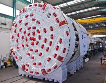


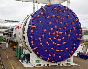
Figure 12-17: Upper row: TBM1 (S-980 Queen Euphemia) andTBM2 (S-981 Queen Ellisiv). Lower row: TBM3 (S-982 Anna from Kloppa) and TBM4 (S-983 Magda Flåtestad) after FAT at Herrenknecht Factory. Photo: Herrenknecht.
Figure 12-18: Baptism the 5th of September 2016 of the two north-heading TBMs by the Prime minister of Norway, Erna Solberg, (#5 from the left) and start-up of the first TBM – Queen Euphemia by the Minister of Transport and Communication, Ketil Solvik Olsen (#6 from the left).
The TBMs 1 and 2, which excavated in the northern direction, from the northern assembly cavern, towards Oslo started excavation in September and October 2016.
The breakthrough of both TBMs heading in the northward direction, took place the 11th of September 2018, just 2 years after start-up of the first machine. The machines had then excavated approximately 9 km each, including pre-grouting in areas where leakages occurred. More details about handling of water leakages are given in Chapter 14 “Geological mapping and follow-up during the TBM excavation” and in Chapter 15 “Groundwater control and monitoring”.


Figure 12-19: Double breakthrough in the north, where the two machines arrived into two parallel caverns. Photo: Nicolas Tourrenc.
The TBMs 3 and 4, which excavated approximately 9 km each in the southern direction, from the southern assembly cavern towards Ski, started excavation on November and December 2016 and achieved both breakthrough the 26th of February 2019. They had
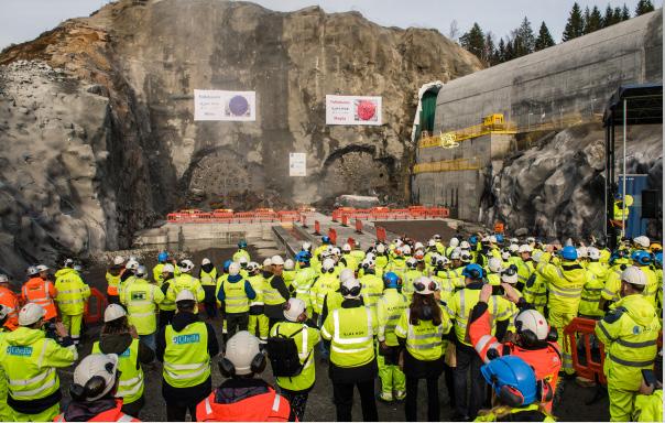
Figure 12-20: Double breakthrough in the south. Photo: Nicolas Tourrenc.
also performed several rounds of pre-grouting in areas with fracture zones, where leakages occurred.
In the table below the main TBM production excavation rates achieved are summarized:

Table 12-1: Summary of the TBMs performance.
The previous figures must be analysed into the following context:
• Almost 8.000 m tunnel were pre-grouted from the TBMs during the excavation of the tunnels. • Pre-grouting affected normal TBM excavation, as no tunnel excavation was possible during this activity. Considered this factor, AGJV managed to achieve the expected TBM production rates (between 14 and 15 m a day). All four TBMs started excavation ahead of the contractual schedule, and the large precast factory at the site started production according to the plan, the excavation of the TBM-tunnels finished according to plan.