13 minute read
Appendix II – Examples of the Quality Control

from Tunnelling in the Follo Line Project - NFF Norwegian Tunnelling Society publication no 29
by TunnelTalk
the exposure was very low while working within the TBM-tunnels, compared with the exposures tunnelworkers are being exposed for by conventional drill and blast. This low exposure could be explained by the fact that the TBMs were electrical, and the transport of rock masses were performed by conveyor belt from the TBM and all the way out to surface. During conventional drill and blasts, the rock masses are transported out after the blasting by diesel driven wheel loaders and dumpers that creates a significantly portion of exhaust. In addition, the experience with this conventional wheel-based mass transport, is that it whirls the stone dust in the entire tunnel and along the transport routes all the way out to the deposit area. All the tunnel workers are exposed for this stone dust, and thereby the number of persons exposed by dust increases, not only those who works at the face.
Advertisement
At the same time as the sample taking was conducted, STAMI also considered what actions that could be implemented to reduce the dust exposure for all the workers during the project. Bane NOR, AGJV, Synergi Helse and STAMI worked together to find out and evaluate actions and barriers to reduce the exposure. Actions that were conducted during the project were:
• A “water curtain” behind the cutterheads • Water mist sprayed on the rock on the conveyor belt on the TBM backup • Mandatory and correct use of the dust masks while changing the cutters • The use of solid one-off disposable suits while working inside the cutterhead • Cleaning/ vacuuming the electrical cabinets, enclosures, centrals, etc. before conducting repair/ maintenance work • Mandatory use of dust masks and gloves, i.e., for electricians who performs repair/maintenance work.
The effect of these actions appeared when comparing the samples taken before and after the actions were implemented. The results were also presented for all the involved workers within the different working areas of the TBMs and of the tunnel. They were informed about the unhealthy dust they could be exposed for by not performing the actions that were made, or by not using the mandatory protective equipment. This resulted in a higher degree of awareness and understanding among the workers for which negative effects the dust exposure could have, both in short and long terms. Another element that contributed to a reduced negative exposure by dust, was drilling with a double shield TBM in combination with the installation of a single shield lining. The results from the study performed from the open TBM-excavation at the Ulriken tunnel project in Bergen, showed that the workers who performed the rock-support and shotcretework were exposed to higher levels of dust than any of the workers in the Follo Line tunnels were during the tunnel-excavation. On a double shield TBM, the concrete lining is mounted inside the shield at the same time in parallel with the drilling, and it is not necessary to conduct any securing work like rock support and/or additional shotcrete in the same way as needed when working with an open TBM.
Conclusion
The samples taken from the health examinations during the study are still being analyzed and the final results are not presented yet. It is therefore too early to make a final conclusion about the exact health effects drilling with TBM may have compared to excavating tunnels by conventional drill and blast. But for sure, based on the analysis results from the exposure samples that were taken and the actions that were performed through the project to reduce the exposure, a positive effect have been measured. The exposure of dust for the workers who operated close to the cutterhead were reduced.
The test results gathered during drilling with the TBMs showed a difference in dust exposure between different groups depending on where on the TBMs or in the tunnel they worked. The longer away from the cutterhead, the lower the exposure. An interesting observation, if you look at the dust exposure from an open TBM, like the one that performed the drilling for the Ulrikken-tunnel in Bergen, compared with the dust exposure from a double shield TBMs in The Follo Line project, the test results showed a lower dust exposure to all the workers working with the double shield TBM. This is probably because working with a double shield TBM, where the concrete lining is mounted during the drilling, the workers are in a lower degree exposed for the negative dust load which comes from the rock support and the shotcreting.
The results analyzed so far also demonstrated that drilling with TBM gave significantly less negative dust exposure from diesel exhaust and rock dust than are created from conventional drill and blast excavation. The main reason for this is related to the use of conveyor-belt for the transportation of the excavated material all the way from the TBMs to the surface. This gives less pollution from exhaust from vehicles and less dust whirled up by the wheels.
It is still great opportunities for the industry to reduce the health impact for tunnel workers by focusing on further development of technical solutions and barriers on TBM. It lies a big potential to reduce the negative health effect of dust, by using a larger amount of time on the organizational barriers like mapping dangers, looking at methods for work operations in different groups, i.e., maintenance staff. Finally; the awareness of each one of the workers, at all levels, knows what they can do to reduce the dust exposure in tunnel work.
Drilling with TBMs as operational system has come to stay, and therefore it is important and necessary that the industry take actions to do what they can to reduce the exposure the workers are exposed for, so the health issues and diseases caused by this exposure reduces as much as possible.
Segment production
Some casting defects and non-conformance were observed during the production of concrete segments for the tunnel lining, many due to different understandings of the contractual requirements. The production took place in three factories on site, 24 hours a day, in order to provide continuous supply to the four TBMs that were operating.
The non-conformances were mainly regarding the following categories:
• The appearance of bug-holes in some segments • Gasket installation out of tolerances • Casting defects (honeycombing etc.) • Quality control procedures (acceptance criteria) • Status and tracking • High curing temperature • Lack of reinforcement cover, mainly in the corner at the extra bar introduced to avoid spalling
Additional measures and preventive actions were taken to improve the quality of the segments, mostly in terms of increased quality control both during production, after demoulding, before loading on transport vehicles and after transportation into the tunnel. The tolerances for bug-holes and defects near the gasket were very strict, and defects could be hard to discover unless inspecting the segments closely. A colour classification system for the status of each segment (approved, rejected or for repair) was agreed between the parties, as well as the repair procedure. During segment inspections, misinterpretation of the acceptance criteria occurred regularly. Objective criteria’s for checking of segments were established. Another repetitive issue was insufficient repair works executed on the segments with defects.
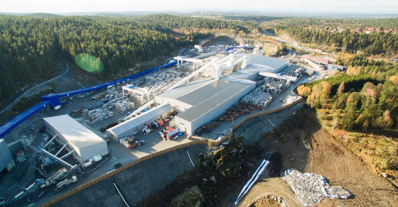
Figure 1: Segment storage at Åsland. Despite continuous work from both parties to resolve the quality issues, the discussions regarding quality of the segments were never properly closed. The different understanding of contract requirements from each party contributed to this. Numerous nonconformance reports were registered from 2017, when the topic was raised, until the production was finished. However, some of the same non-conformance found in the beginning of production were still observed at the end of the production.
In general, any consequences of undetected quality deviations in any tunnel project are difficult to predict. It is difficult to replace segments once they are installed in the tunnel, and any defects near gasket or on wet side are impossible to discover or repair after installation. The segmental lining is designed for service life of 100 years.
The tunnel segment factory layout was designed at an early stage in the project and was a part of the total layout of Åsland site. The layout was focused on logistics processes, with effective transport of elements out from the factories and directly into stacks of one and a half tunnel rings in the storage area. The layout did not consider the possibility of large numbers of rejected or quarantined segments, and how to handle those. It was possible to put a side a small number of segments at the entrance of the pre-storage in the factories, but the space was limited. With the increasing number of quarantined and rejected segments, it became more and more difficult to physically separate them from approved segments. Even though if a space could be allocated, the physical movement of such segments was difficult due the constraint on crane moving capacity, as the cranes priority was to feed the MSVs taking segments to the tunnel.
It meant that physical storage of quarantined segments was not separated fully from accepted segments. Instead, it was implemented a system with spray paint to indicate if a segment was accepted, quarantined, or rejected. This system had however weaknesses, as status could be changed from for example “accepted” to “quarantine”, and in such cases, new marking could only be done when the quality team had time to locate the segment and make a new mark.
To keep track of status of segments, quality department maintained a system to register and maintain status of segments, and from this register lists of
segments were given to logistics, who would pick segments from those lists. A database segment tracking system was implemented in the project, which included handheld scanners to keep track of each segment. However, standard functionality of this system did not include any quality status functionality.
The main lessons learned:
• Layout of factory and storage area should include a plan for how to handle rejected and quarantined segments, including a dedicated storage area. • Segment tracking system should include quality status functionality. • Acceptance criteria discussions to be formally finalised as early as possible, thus limiting the number of quarantined segments.
The main problem which never fully could be solved, were the bug-holes that tended to appear below the gasket. A low slump concrete was used together with a cast-in gasket, and the air trapped under the gasket was very difficult to avoid.
Lessons learned from this is:
• In design, when choosing between cast-in gasket and glued gasket, the problem of trapping air below the gasket should be taken into consideration, • The production process should, if possible, be planned with measures to avoid bigger amount of trapped air. • If cast in gaskets to be applied, perform more tests, and achieve more knowledge about the real consequence of a bug-hole below the gasket (as there is pr today no satisfying technical explanation on the requirement) • Repair procedures, including for bug-holes at the gasket, should be developed and agreed before segment production starts. Contractor rejected approximately 1500 segments out of 141.000 units, due to the bug-hole close to the gasket problem. In addition, the visual control of such defects was a somewhat unprecise task, and subject to individual’s assessments.
Drainage system
Several quality issues occurred during installation of the main drainage system in the tunnel, both for the main drainpipe under the slab track and for connected lateral pipes collecting surface water.
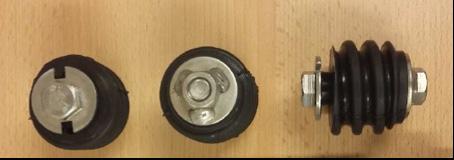
Every 80 meter there are lateral drainage pipes of diameter 75 mm, leading the excess surface water into the drainage system. The 75 mm pipes are cast into the invert slab, and the cast-in pipe was designed with a slope of 1% towards the manhole. However, the pipes were quite flexible, and the buoyancy of the empty pipe in the concrete provided some challenges on how to obtain an even and correct slope.
The initial procedure was to attach the pipe to the underlaying slab in two points. Some discussions took place regarding interval of fastening points for the main drainage pipe, but the smaller lateral pipes were not given the same level of attention. As the construction started, it was observed that the pipes were placed with wrong slope and bulging even before concreting. After concreting, the only way to control the actual built slope was by video inspection. However, this was not performed successively as the works proceeded in the tunnel, but it commenced after many kilometers of drainage were installed.
When video inspection finally was carried out, many of the lateral 75 mm pipes proved to have wrong slope and could not be accepted. Thus, the concrete had to be removed and the pipes replaced. For the remaining minority of pipes, the procedure was changed to obtain the correct slope after concreting.


Figure 2: Left: Not properly fixed. Right: Properly installed and fixed.
Video inspection also uncovered quality issues for the main drainpipe. The main drainpipe is a corrugated double layer PE pipe of dimension 315 mm and is placed in a pre-cut channel in the invert segments before being cast-in by concrete. The pipe is located under the slab track and is transporting all water from the tunnel. The video inspections started while performing the drainage construction and revealed a substantial number of cracks, damages, and displaced joints throughout the tunnel. After video inspection commenced, corrective actions were taken which improved the frequency of imperfections in the pipes. This must have occurred during installation and concreting around the pipe, as the damages were not discovered before concreting. Leakage tests showed no leakages. Long-time consequences of these deviations are difficult to predict, but one outcome can be increased accumulation of sedimentation and lime deposits due to unevenness of the pipe. This again may lead to a demand for more frequent flushing and maintenance of the drainage system. In the frost zone, the main drain was isolated, but the isolation is not watertight, so cracks in the pipe and displaced joints can cause problems if water eventually enter the surrounding concrete, and cause damages when freezing. In the frost zone, leakage tests and video inspections were performed, and no fractures or other kinds of damages of the pipes were identified. The point is that it is important to have a specific focus on quality in the frost zone, and make sure that leakages will not occur in this area.
There have been other incidents as well regarding the drainage, such as concrete spill in the drainage and grout blocking drainage pipes. This has been identified and solved.
The lesson learned from these incidents is that a more rigid pipe for similar construction activities in the future shall be considered. By doing video spot checks at various stages during construction, such deviations can be spotted early, and construction procedures can be changed as required.
Permanent way
The tracks in the tunnel are ballastless tracks, where a system with bi-block sleepers cast in a concrete slab has been applied. The slab track is executed as a continuous operation of sleeper and track installation, surveying control and concreting, ongoing for 24 hours per day. As the sleepers are cast into a concrete slab, there is no room for adjustment of the sleeper position afterwards, and installation must be done correctly the first time. The concrete slab must also be executed correctly, with correct level and slope.
Before start-up of the slab track, there were several meetings regarding quality level and quality control of the works. A small mock-up was made to demonstrate the quality level of the concrete surface finish and to test the set-up of equipment, with which all parties were satisfied. However, when the actual works started, numerous unexpected quality issues occurred, many of them again due to a lack of common understanding of the requirements.
Examples of such issues are:
• Uncontrolled cracking of the concrete slab • Poor reinforcement cover • Uneven and rough surface with depressions • Excessive amount of water in the areas of concreting • Too large sleeper spacing • Spalling and other surface defects • Trouble with clogging of the concrete pumping pipe


Figure 3: Left: Insufficient crack inducer. Right: Sufficient crack inducer.