24 minute read
15 Groundwater control and monitoring

from Tunnelling in the Follo Line Project - NFF Norwegian Tunnelling Society publication no 29
by TunnelTalk
Johannes Gollegger, Bane NOR Jørn Grøndal, Bane NOR Anne Kathrine Kalager, Bane NOR
Introduction
Advertisement
The paper covers relevant aspects of ground water control and monitoring of the Follo Line project. Based on the geological and hydrogeological ground characterisation, the contract requirements for water tightness and strategy for ground water control are described. During project execution it became obvious that the measures for dealing with water ingress had to be improved significantly. The final concept included several probe drills depending on the sensitivity of the area with rather strict water leakage limits for pre-excavation grouting, resulting in many pre-excavation grouting rounds.
Many tunnel projects must consider the risk of highwater ingress during the construction phase, resulting in pore pressure reduction in both rock and soil above the tunnel. In Norway, the risk of settlements in sensitive/ marine clay sediments and draining wetlands is particularly high. It follows that it is crucial to identify areas sensitive to pore pressure reduction above the tunnel alignment during the design phase. The reason for this is that the isostatic uplift after the last ice age and settlement in sensitive marine clays are often located in rock surface depressions. Infrastructure and buildings constructed on top of these sediments are therefore exposed to the risk of pore pressure reduction resulting in settlements during tunnel excavation. Avoiding any kind of damage to vulnerable vegetation above the tunnel alignment is also important.
Geological conditions
The rocks in the Follo Line project area consist predominantly of Precambrian gneisses. A significant number of intrusives from the Perm period, as well as amphibolite dykes/sills occur. The amphibolite dykes/sills are more prevalent in the project area than the Permian intrusives. Most dykes/sills are a few metres thick, with a small proportion thicker than 10 m. Sedimentary shale occurs in a very short part in the North towards Oslo Central Station.
The Precambrian gneisses are folded in sharp isoclinal folds and they expose a clear foliation. The dominant rock structure in the project area strikes N-S to NW-SE. Farthest south towards Ski, the structure turns over to an E-W orientation. Fractured layers in the gneiss have been exposed to erosion due to mineral composition (high mica or amphibole content), often in combination with fault offsets which have resulted in long, prominent ridges and valleys. Several groups of fracture zones strike across the structure of the gneiss.
The average joint spacing for the various joint sets observed at the surface does not seem to be influenced by the proximity to the fault zones. One reason for this may be that some rock exposures are small, making it difficult to determine the general joint spacing. Another reason may be that random joints are not included in the average joint spacing, as these joints do not belong to any joint set. A third reason is that areas most strongly influenced by the fault zones usually form soil covered depressions in the terrain and therefore do not show rock exposures at the surface.
The superficial deposits in the project area are mainly of marine origin. Normally there is also a moraine layer on the rock surface. In addition, some limited areas are covered by organic deposits (peat/ bog). Fundamentally, marine- and organic deposits are settlement sensitive. Whether or not settlements will occur, as a result of groundwater lowering, depends on several conditions. In particular type of deposit, properties, horizontal extension, and ground water level.
Hydrogeological conditions
Groundwater is primarily restricted to fissures-, fractures- and fault zones in the basement rocks. In some few areas restricted groundwater aquifers can be found in the overburden along the alignment especially along rivers, streams, and bogs.
Hydraulic conductivity measurements have not been conducted in the overburden. Hence neither the hydraulic conductivity (permeability) nor the porosity of the overburden in the project area is known in detail. The effective porosity of clay is seldom more than 1to10 % of the total volume of the clay deposit.
The range for hydraulic conductivity in fractured crystalline rock in Norway is 10-4 to 10-8 m/s, and the porosity in the range of less than 1to5 %. Hence for all practical purposes, groundwater is assumed to be located mainly in fissures, fracture and fault zones. Possibilities of draining groundwater aquifers and surface areas above the tunnel are therefore
related to the fracture pattern and the degree of fracturing.
Contract requirements
The contract set out several requirements related to water ingress control.
First, lowering of the pore pressure below natural variations shall not occur. For handling of unacceptable water ingress and to prevent pore pressure reduction, pre-excavation grouting and/or water infiltration wells during construction shall be applied. The project owner prepared a detailed specification for pre-excavation grouting, which was provided to tenderers as an information document. Contractor was supposed to develop its own specification depending on its construction procedure and materials for backfill grouting of the ring gap.
Systematic grouting was mandatory in areas of very high sensitivity to settlement in the D&B sections of the rescue area tunnel and in the cross passages.
For areas where settlements could cause damage to buildings or other infrastructure, or where drainage into the tunnel was deemed likely to negatively affect the natural environment, a sensitivity classification was provided. This is shown in Table 15-1 below.
Table 15-1: Classification of sensitivity zones along the entire tunnel.
The classification depended on the risk related to pore pressure reduction of the area located above the tunnel and the occurrence of fractured zones. The risk was related to both settlement of buildings founded on soil deposits and sensitive natural environment.
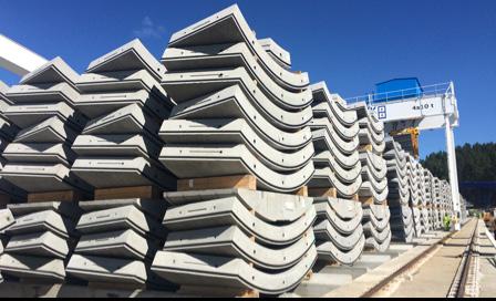
In the TBM tunnels, a segmental lining with gaskets was chosen as waterproofing concept, and rock support. See figure 15-1 below. All D&B structures, like the rescue area tunnels, the escape tunnels and the cross passage are built as drained tunnels with rock support, water membrane and inner lining.

Figure 15-1: Segmental lining installed in the tunnel.
Contractor was required to ensure a dry tunnel and no dripping/visible flow of water was permitted whatsoever. In the event that such wet spots appear, whether through the joints between the segments or through the body of the segments, the contractor was required to propose and carry out remedial measures.
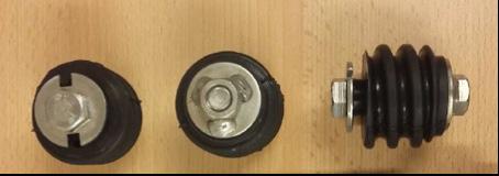
The gasket should be an EPDM (Ethlylene Propylene Diene Monomer) with high elasticity and low relaxation from the maximum water pressure over the design life.
Contractor should ensure water tightness of the connection between the segmental lining and the adjacent concrete structures, such as
• D&B (drill and blast) tunnel in the north • Concrete tunnel in the south • Cross passages • Rescue area
Building inspections
Shortly before the tunnel excavation started the different neighbourhoods of the tunnel, all buildings located close to the tunnel-corridor were inspected internally in all rooms, including basements and attics. This also applied to any surrounding buildings like garages and parking basements.
All surfaces needed to be registered and the inspection should cover all existing damages like:
• Cracks in walls, floors, and ceilings • Cracks in glasses and windows • Cracks or chipping in ceramic tiles • Moisture and traces of water leaks • All doors and windows shall be checked for possible malfunction • Potential settlements shall be registered
In addition to normal inspections, comprehensive inspections also included the following:
• Straightness of floors and possible building inclinations were documented by means of levelling. If inclinations were detected, they were illustrated with a sketch / drawing. • Cracks were plugged to follow any further developments. • Control inspection / registration just before the construction start and at the end of the construction period.
The inspections should be done with an HD camcorder. Lamps should be used where lack of light would otherwise impair the quality of the recordings. During recording, verbal comments for explanations were also performed. The recording of each unit should start with general information about the property and building, which should also include, among other things unambiguous identification of the property like address, date of inspection, who was present, etc. Provider should also state what type of equipment was used.
Exterior facades were inspected from street level unless special conditions indicated otherwise. If required, was the inspection done by boom lift. Exterior window posts and window frames etc. should be filmed as well to document any damage, usually done from inside with open windows. Exteriors should also be filmed with balconies or other structures providing access to exterior surfaces.
Exterior inspections should be avoided immediately after heavy snowfalls, when snow covered larger sections of exterior structures.
All exterior structures (bridges, walls, stairs, basins, monuments etc) should be inspected. The inspections should be so extensive that existing distortions and cracks could be documented.
In total, the Follo line project has carried out the following inspections:
• Detached dwelling units / townhouses etc. 2506 units • Flats in apartment blocks 1520 units • Commercial / industrial areas - furnished 294 230 sqm • Commercial / industrial areas - unfurnished 32 311 sqm
Water monitoring program
An extensive monitoring program consisting of 170 pore pressure sensors in both soil and rock wells was established in due time before tunnel construction in order to register the natural seasonal variations in pore pressures. See figure 15-2 below.
The development of the monitoring program was a continuous and ongoing process throughout the project. After TBM excavation started, the number of sensors and the packer locations were updated based on experiences gained from the TBM excavation, in combination with geological mapping and the measurements from the pre-installed sensors. All sensors were logged automatically, and the readings were uploaded to a web-based GIS portal with a frequency of every 10th minute.
In addition to the pore pressure monitoring program, an extensive settlement program was carried out. Nails were installed on the foundation of more than 2,500 dwellings. The nails were manually surveyed in due time prior to passing with the TBMs and after the TBMs had passed, and the readings were uploaded to a web portal. In addition to the pore pressure and settlement nails, a monitoring program utilizing satellite data (InSAR) from 2014 and up to date was established.

Figure 15-2: Pore pressure measured from 2014 and until both TBMs had passed and the pore pressure situation had stabilized.
Probe drilling and pre-grouting concept
The contract required continuous and overlapping probe holes, at all times for each TBM tunnel. The number of probe holes were determined by the sensitivity classification. See table 15-1 above.
Considering the fact that the tunnels were excavated with double shield TBMs, the aim of the probe drilling was to perform water ingress measurements from the holes in order to assess the further need for pre-grouting. Pre-grouting was performed to limit the leakages during excavation. There were 38 holes around the shield from where it was possible to perform probe drilling from the TBMs. This is illustrated in figure 15-3 below.


Figure 15-3: The cutterhead with the 38 inclined ports with 11o drill angle and DN80 pipes for probe-drilling. Illustration: Herrenknecht/ Acciona Ghella Joint Venture.
For the areas classified with “small sensitivity” contractor’s concept was to drill minimum two holes of 35 – 40 m from each machine during the daily maintenance shift.
The pre-grouting was performed either systematically in the mandatory areas, or when deemed necessary based on water ingress measurements from probe drillings. The trigger values from water ingress measurements were based on the sensitivity class of the areas above. During the excavation, the number of probe holes and the trigger values were optimized in order to maintain the groundwater balance.
Infiltration wells
A total of 28 temporary infiltration wells were installed at 13 different locations. The wells were operated from surface and acted as additional mitigation measure for groundwater control whilst the TBMs passed. The wells were successfully operated. The infiltration wells were drilled 20-50 m in rock, preferably inclined under soil deposits, se figure 15-4. Water with some overpressure was infiltrated through the rock well and into fractures in the rock. Both pressure and flow were controlled to avoid piping effects in the overlying soil.
Experiences
TBM excavation
The first construction method statement for preexcavation grouting submitted by contractor was basically a copy of the client’s original proposal without considering the specific boundary conditions of the bi-component backfill material for the ring gap. contractor decided to fill the ring gap from 2 o’clock position to 10 o’clock position through the grout ports in the tail shield and then fill the crown area from the back-up, without having any possibility for re-injection along the back-up. This meant that no water barriers were installed on the back-up to avoid water running behind the lining along the TBM tunnel and entering in front of the installed segments. Without having this possibility, the construction concept was fully dependent on the success of pre-excavation grouting. The limits established by the client for pre-excavation grouting were assuming a watertight tunnel behind the TBM, and water barriers to avoid water running along the TBM tunnel. As a consequence of this, the trigger values for pre-excavation grouting had to be reduced several times.
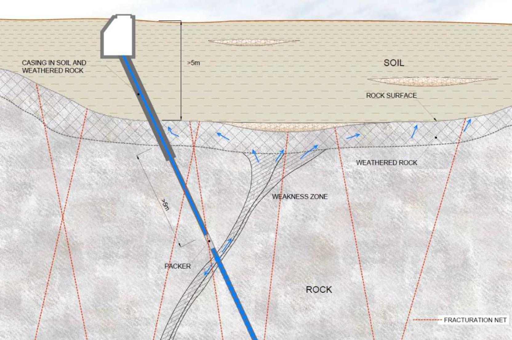
Figure 15-4: Principle of an infiltration through a fracture zone. Illustration: AGJV.

Table 15-2: Trigger values for pre-excavation grouting in Bane NORs original concept.
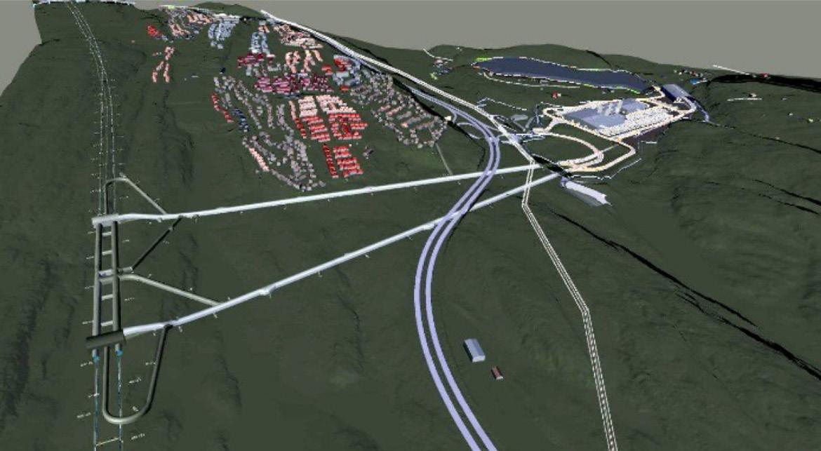
Figure 15-5: A network of fracture zones (purple color) and black rings marking the position of the TBMs at specific dates and the location of the affected residential area. Table 15-3: Adjusted trigger values for pre-excavation grouting during the excavation period.
This learning curve resulted, especially at the beginning of the TBM excavation, in water ingress into the tunnels, which caused a lowering of the pore pressure in the sediments above the tunnel. The water entering had high content of bi-component backfill material, which required an exhaustive water treatment.
On the 7th of December 2016, TBM 4 boring in the southward direction, crossed a semi-horizontal fracture zone, which resulted in water leakage into the tunnel. In this area, only one probe hole, located in the upper part of the profile had been performed, and this was not sufficient to detect the water-bearing cracks. Therefore, no pre-excavation grouting had been carried out in advance to stop the water ingress when the TBM hit the fracture zone. It took several weeks until the situation was brought under control. TBM 3 also entered the same zone and suffered water ingress as well since no pre-excavation grouting having been done in this case either. The immediate amount of leakage in TBM 4 was somewhat uncertain. On the 8th of December 37 l/s was measured and from the 23rd of December to 3rd of January the average was 14 l/s. These leaks did probably cause settlements on buildings in a residential area located at a direct distance of 700 m in a horizontal line from the tunnel alignment. On the 7th of December 2016, the tunnel face was approximately 1300 m in a horizontal line from this area, and on the 17th of March the distance was approx. 900 m. This was outside the area that originally was expected to be affected by the pore pressure reduction due to the tunnel operation. As shown in figure 15-5, the tunnels crossed a network of fracture zones with N-S and NE-SW directions. Each of this fracture zones illustrated in the map have a thickness of more than one meter. In between there may be fracture zones with less thickness as well. The network of fractured zones acted as drainage channels, which contributed to reduce the pore pressure in sediments located quite far from the tunnel-corridor. This is also described in Chapter 14, “Geological mapping and follow-up during the TBM excavation”.


In summer 2017, the project organization became aware of development of possible settlements in the residential area located 700 meters from the tunnel corridor. Two pore pressure sensors had been installed there, 7060-1 and 7060-2, at 5.4 and 8.4 m depth, respectively. Figure 15-6 shows relevant pore pressure fall and water level measurements in the rock close to the tunnel alignment. The pore pressure in the deepest meter was then about -4 m compared to the stabilised value at the end of 2017. This, together with several other pore pressure sensors, located closer to the tunnel alignment, which had shown declines, had all stabilised. A well at a nearby farm, also at this area, went dry while the pore pressure was reduced on the affected residential area, but recovered later.
Some of the houses in this area are founded on rock, whilst in some specific cases the basement floors are founded on soft ground (marine clay and some peat). An analysis of InSAR settlement data showed ongoing settlements for the buildings over several years, however it appeared that the water ingress into the tunnel, with corresponding temporary pore pressure reduction in this area, accelerated these
settlements for a short period. Since this area was outside the initial detailed monitoring zone of the project (350 m on each side of the corridor), a limited number of data were available for these specific cases. When the TBMs had passed this area, and the water leakages into the tunnel had been stopped, the pore pressures were re-established. The project took responsibility for the temporary drop of the pore pressure and for the development of settlements in the affected areas and repaired identified damages of buildings.
Experience have shown that areas far away from the tunnels (in this case > 1300 m) can be affected by pore pressure and water reductions due to tunnel excavation, if large leaks are not sealed quickly. In soft soil areas, this can lead to drainage and settlements of buildings.
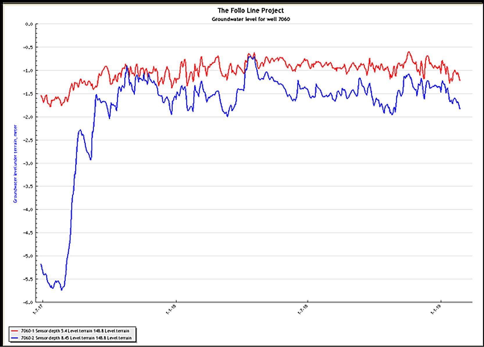
Figure 15-6: Measured porepressure levels in the area close to the affected residential area.
Another example is taken from the TBM drive towards Oslo, in the northward direction.
As TBM 1 and 2 approached a specific residential area in the autumn of Oct / Nov 2017, pore pressures reacted almost instantaneously in both south and north areas of the positions of the TBMs. The farmland here was particularly exposed. Settlements were previously shown here while the work on a new construction area was completed in 2015/16. This had resulted in occasional settlements in this area of up to 10-15 mm. During the fall of 2017, a new pore pressure reduction of approximately 8 m was detected at sensor 4857 and reactions in several other sensors were also registered. This is shown in figure 15-7 below. Pre-excavation grouting from the TBMs was performed before passing under the area, but only when the segmental lining was in place did the pore pressures rise again to normal levels. The pore pressure reductions resulted in settlements of up to 25 mm, which is shown in figure 15-8. The settlements started as soon as the pore pressures dropped, and they stopped as suddenly as they started when
the pore pressures were up again. The settlements appeared to be of a relatively harmless type. No significant damages were reported. That was probably because the differential settlements seemed to be small. Water infiltration from three different rock wells in the area may have had some significance effect to bring the pore pressure up again. The water infiltration wells were temporary until leakages into the tunnel had been stopped. When a pore pressure balance was achieved, the infiltration wells were demobilised.
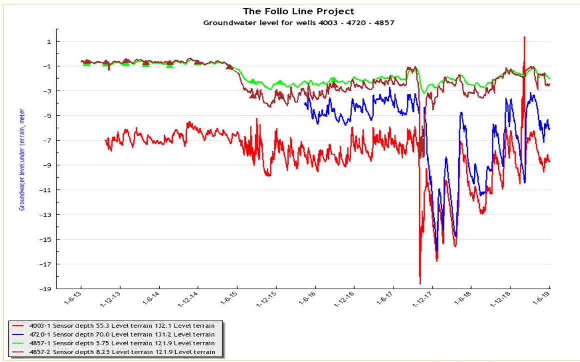
Figure 15-7: Pore pressure levels in one of the affected areas in the northern part of the tunnel. It showed a significant drop while the TBMs passed and were not re-established before the leakages into the tunnel and the cross passages had been stopped.
0
-10
setning i mm -20
-30
-40
-50
01.06.13 01.09.13 01.12.13 01.03.14 01.06.14 01.09.14 01.12.14 01.03.15 01.06.15 01.09.15 01.12.15 01.03.16 Dato 01.06.16 01.09.16
01.12.16 Bolt 1 Bolt 2 Bolt 3 Bolt 4 01.03.17 01.06.17 01.09.17 01.12.17 01.03.18 01.06.18 01.09.18 01.12.18
Figure 15-8: Development of settlements in the affected area corresponding to the pore pressure situation shown in figure 15-7 above.
As a result of the water ingress through the TBM shield, a reaction was registered in observation wells in rock almost one kilometre from the tunnel alignment. This shows that probe drilling in front of the TBM with a sufficient number of probe holes, customised for the geological conditions and the sensitivity zone classification, are essential to detect fractures with high permeability and to avoid situations like this.
In the beginning of the excavation period, the contractor decided to start with performing only one probe hole located at top centre position and drilled approximately 30 m in front of the TBM cutter head. Later experience showed that this strategy was not sufficient to detect all fractures with high permeability. A revised strategy for the probe holes was implemented to adapt to the encountered geology. The new concept involved minimum two holes, located at top and invert of the tunnel, which was also more in line with the client’s advice in the tender documents. The leakage criteria for when to start pre-grouting from the TBMs were also revised. Trigger values at the Follo Line project were, after some experience, set to 40 l/min total from minimum two probe holes in moderate to sensitive areas. Experience showed that increasing the number of probe holes to four provided more reliable information of the conditions ahead of the TBMs. It was then also possible to detect fracture zones which crossed the tunnel with a small angle before they were hit by the TBMs. In areas with small sensitivity, around 80 l/min was experienced as a maximum value for water ingress to avoid problems with the backfill grout. In some of the sensitive areas, the number of probe holes were increased to six and the trigger level reduced to 25 l/min in total from all the probe holes, whilst mandatory pre-grouting was required for some of the areas classified as very highly sensitive. In other areas, defined as very highly sensitive, the trigger value for starting pre-grouting was set to 8 l/min in total from all the six probe holes.
Based on experience during the excavation, the number of systematic probe holes were increased for all the sensitivity classes, and the trigger values for starting pre-grouting were reduced. The development of trigger values is illustrated in figure 15-9 below.

Figure 15-9: Reduction of the trigger values from different number of probe holes for starting pre-grouting during the excavation phase.
Another observation in areas with leakages through fracture zones, was that the water ingress also resulted in outwash of the cement based backfill which was injected behind the lining. This outwash increased the water flow behind the lining, which resulted in even more outwash of material, and in some cases a destabilizing of the lining as well. From an early stage of the excavation period, it was obvious that the contractor needed to improve their strategy and methods for handling the water as an integrated part of their construction.
As a consequence, many pre-excavation grouting rounds were performed, and in total 7.637 meters of the tunnels were pre-grouted. In the beginning, contractor used approximately 30 hours at the entire process, from probe drilling until finalizing one pre-grouting umbrella. In the end of the excavation phase, the time needed to perform the entire sequence was reduced to approximately 15 hours.
Contractor did never inject more than 20 holes in one umbrella, even though it was possible to inject from 38 exits. By utilizing all the exits when drilling for the umbrella, the quality of the injections would have been improved, and in some areas the water behind the lining, including the outwash of backfill material, would probably have been reduced.
The two TBMs which excavated in the southward direction crossed more fracture zones than the TBMs heading northwards. As a consequence of that, a higher number of pre-grouting rounds were performed in the south than in the north, 40 – 65% more. TBM 4 was ahead of TBM 3 most of the time, and TBM 3 may have had some benefit of the pregrouting performed from TBM 4. This is shown in Table 15-4 below.
The amount of cement used in the different pregrouting rounds varied, but for the two machines heading south, the average volumes seem to be more or less the same. These volumes are comparable to the volumes per round and also per hole
TBM
1
2
3
4
Total Number of pregrouting rounds
67
66
92
109
334
Table 15-4: Number of pre-grouting rounds for each of the TBMs.
Table 15-5: Cement volumes used for pre-grouting for each of the TBMs.
measured for TBM 1. The volumes for TBM 2 are lower. One of the reasons for this may be that TBM 2 were behind TBM 1, and may have had benefits of that, even though the number of pre-grouting rounds were approximately the same. The volumes are shown in table 15-5 below.
Cross-passage excavation
The cross-passage excavation is always a critical operation in a twin tunnel concept. Loads from the segmental lining need to be transferred to adjacent rings and water ingress shall be avoided. Since the TBM tunnels were excavated in stable rock mass, the ground loads were relatively small, and the main loads were water loads. The design was optimised in a way that only three special segmental lining rings for the opening area were required.
The procedure for excavation of cross passages, similar to the TBM excavation, had focus on reduction of water ingress and during a learning process, the construction method statement experienced several revisions. At the beginning basically no contact grouting was performed in the TBM tunnels in order to reduce water ingress from the main tunnels, only rock mass grouting from the main tunnels into the cross-passage areas were performed. This concept resulted in uncontrolled water ingress at the cross-passage openings, which resulted in a lower-
TBM Total amount of cement Average volume of cement per round
1 1 225 651 L 18 293 L
2 1 005 078 L 15 228 L
3 1 634 488 L 18 365 L
4 1 541 062 L 17 123 L
Average volume of cement per hole
915 L
761 L
918 L
915 L
ing of the pore pressure and the groundwater levels. A typical behaviour is illustrated in figure 15-7 above. The drops after the TBMs passed can be related to cross passage openings in the area.
A combination of cementitious grout performed as contact grouting and injection of polyurethane rings around the cross passage opening provided sufficient reduction in the water ingress from the main tunnels during opening. In fractured zones, rock mass grouting was required as well.
The most effective method in terms of water ingress reduction was pre-excavation grouting from the TBM as a preparation for the later opening of the crosspassage. At a certain point, this decision was taken to perform pre-excavation grouting from the TBM at cross passage openings, usually with two umbrellas. This is described in more details in Chapter 13, “Opening and excavation of the cross-passages”.
Conclusion
In total, the handling of water improved during the excavation phase, and in the end the detection of water and the performance of pre-grouting were executed in an efficient way. The result was limited periods with reduced pore pressure and limited settlements on affected buildings.
A lesson learned is the importance of paying attention to areas where leakages may occur, and of being well prepared to handle the leakages in advance by pre-grouting. Good knowledge and understanding of the geological conditions are always one of the key factors to success. Another crucial factor for the project was to prepare the TBMs for pre-grouting. During the excavation, a utilization of the opportunities to improve the quality of the pre-grouting umbrellas by injecting more holes, could have been done. This could have reduced some of the leakages that occurred through the lining, and then the need for performing post-grouting.
One of the main success factors regarding water tightness is a 100% filled ring gap to limit the amount of water just behind the lining. This can usually only be achieved, if additional round of injections are performed after the first ring gap filling, especially when washouts may have occurred.
On the other side, the machines excavated 9 km of tunnels each within a period of approximately two years, even though they performed pre-grouting over a total length of 7.637 meters. This execution has demonstrated that neither the hard Norwegian rock, nor the need for doing pre-grouting in order to stop or reduce water-leakages are show-stoppers for TBM-tunnelling.