22 minute read
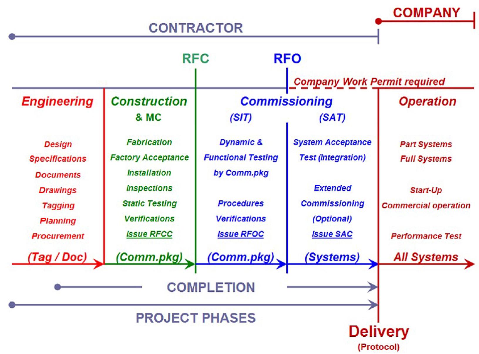
11 Challenges with tunnel excavation close to existing sensitive infrastructure

from Tunnelling in the Follo Line Project - NFF Norwegian Tunnelling Society publication no 29
by TunnelTalk

Helene Kristiansen Andersen, Bane NOR Anne Kathrine Kalager, Bane NOR
Background and challenges
Advertisement
The entrance of the two Follo Line tunnels to Oslo Central station had to satisfy all the requirements needed to ensure the access to the necessary platforms without any conflict with the other tracks going in and out of that busy station. Furthermore, the Directorate of Cultural Heritage had several requirements linked to the preservation of Medieval cultural heritage areas close to the station. Because of this, the existing Østfold Line had to be relocated close to Oslo Central station.
Moving south from Oslo Central station, the Follo Line crosses under the Medieval park and a track area, called Loenga, in a concrete culvert. The culvert leads to the Ekeberg Hill, where the Follo Line tunnels and the inbound Østfold line continue in rock tunnels. The outbound Østfold Line continues in the existing track along the harbor on the outside of the Ekeberg Hill, 1,7 km to Sydhavna. At this point, the inbound Østfold line exits the tunnel, connect with the existing track, and continues south.
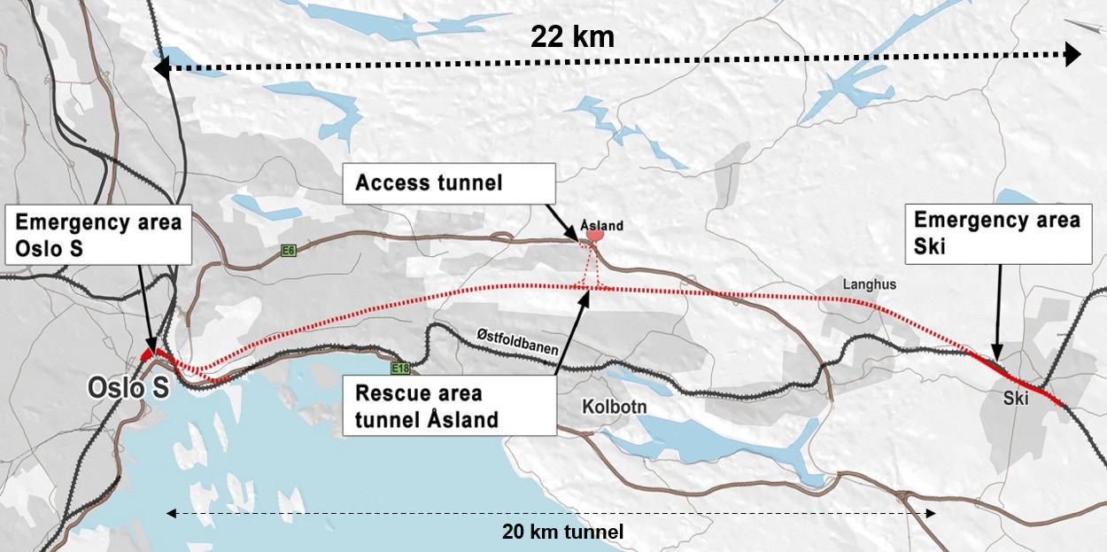
The Follo Line continue south towards Ski, in two 20 km long tunnels, see figure 11-1.
In this northern part of the tunnel, the two Follo Line tunnels and the Inbound Østfold-Line tunnel are crossing close to other sensitive infrastructure, as different tunnels, caverns, and technical installations. See figure 11-2 and 11-3.
To avoid damages of the objects which were located close to the new tunnels, specific preparations were done in advance and other suitable mitigations were implemented during the excavation of the tunnels.
Figure 11-1: The Follo Line 20 km long tunnel and inbound Østfold Line 1,7 km long tunnel.
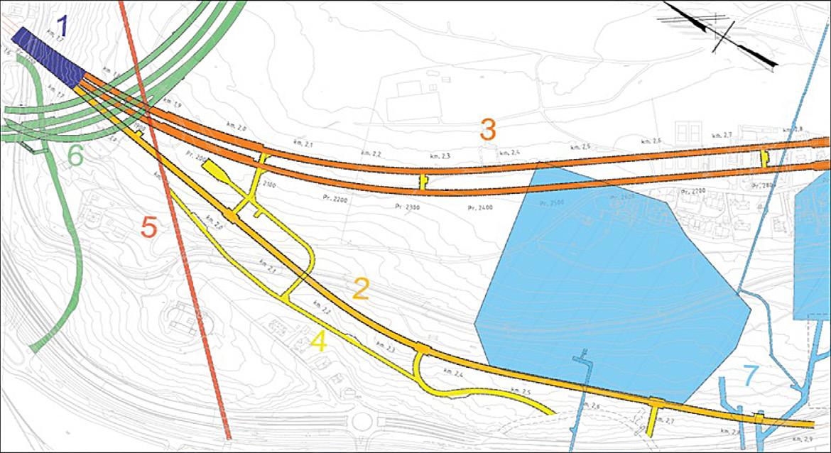
Figure 11-2: Map of the tunnels in the northern part of the Ekeberg Hill. 1) Three Track Tunnel, 2) Inbound Østfold Line, 3) Inbound and outbound Follo Line tunnels, 4) Access tunnels and technical rooms, 5) Alna river tunnel, 6) E6-Ekeberg tunnel, 7) Petroleum storage caverns.

Figure 11-3: Existing and new infrastructure in the Ekeberg Hill. The blue circles indicate the areas where the crossings between the new and existing infrastructure occur, during the construction of the Follo Line project.
Crossing under the Alna River tunnel and the E6 road tunnel
The three railway tunnels cross under the E6 main road tunnel and under the exit and entry ramps for the road tunnels. The distance between the crown in the railway tunnels and the invert in the road tunnel is at smallest 3.5m. Between the railway and the road tunnels is a tunnel for the Alna river located, going from the Kværner valley down to the harbor. At an early stage in the planning, this crossing was pointed out as a critical crossing due to the low overburden between the new and existing infrastructure
Crossing of the storage caverns with petroleum products
There are strict requirements when planning the geometry of new railway tracks. Due to the geometry of the Follo Line it was not possible to avoid crossing close to the caverns for storage of petroleum products. Approximately 1 km inside the Ekeberg Hill all the three railway tunnels come close to, or cross above some parts of the storage caverns or their infrastructure. This includes the caverns, technical installations controlling the pumping of the petroleum products, in addition to ventilation systems. The storage caverns supply most of the area surrounding Oslo with petroleum products, including Oslo airport Gardermoen. Therefore, any disturbance in the delivery chain would have severe economic and societal consequences.
Crossing through the escape tunnel from the petroleum storage caverns
From the storage caverns with petroleum products, there is a 2 km long escape tunnel. It was not possible to avoid conflict between this tunnel and the two Follo Line tunnels. In accordance with the agreement with the owners, the escape tunnel had to be open and operational throughout and after the construction period. The solution was to build a bypass tunnel under the new Follo Line tunnels. This by-pass had to be finalized and in operation before the construction of the two Follo Line tubes could take place.
Establishing the tunnel entrance for the Inbound Østfold line at Sydhavna
The tunnel entrance for the inbound Østfold Line is very close to the existing track. The portal comes out on a plateau underneath a concrete bridge construction for the E18 main road. Thus, the construction was planned to take place close to a highly trafficked main road and railway line, as well. The access to the site was challenging and was a critical element in the project. There were linked several restrictions to the work to avoid damaging the existing infrastructure or disturbance of the traffic on both the road and the railway.
Crossing between two sewage tunnels
The two Follo Line tunnels cross right under the old Kværner sewage tunnel and right above the new Midtgardsormen sewage tunnel, in an area where the two sewage-tunnels also cross each other. The distance between the Follo Line tunnels and the Kværner tunnel is at the smallest approx. 1,35 m. The Kværner tunnel is an old and unlined tunnel where the blasted profiles vary. Between the Follo Line and Midtgardsormen, the smallest distance is ca 0.5 m. The new sewage tunnel was built during the design phase of the Follo line, and exact information with respect to location and design were available. This crossing for the Follo Line tunnels was performed by the two tunnel boring machines (TBM).
Method of excavation of the tunnels in the northern part Ekeberg Hill
In an early stage of the project, it was determined that it would not be suitable to excavate the inbound Østfold Line tunnel by a TBM. It was not space enough to neither assembly nor disassembly a TBM in none of the ends of this tunnel section. It was therefore decided to excavate the inbound Østfold Line by using careful drill and blast methodology.
It would have been possible to continue the TBM excavation from the south, for the two Follo Line tunnels in the northern part of the Ekeberg Hill. This, however, would have been the last part of tunnel excavation of 10.5 km, and it would have been on the critical path for the entire Follo Line project. To reduce the risk of delaying the entire project, it was decided to excavate the northern 2 km of the 20 km long tunnel by careful blasting. To ensure a good progress on this part of the project, the work was performed as a separate contract, awarded early and independent of the TBM-contract. This is described in more detail in Chapter 2 “Excavation method for the different parts of the tunnel”
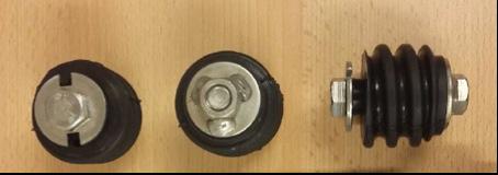
The owners of the nearby infrastructure were critical to the use of explosives close to their sensitive systems. As a compromise, it was decided, after careful consideration, to excavate the parts of the new railway tunnels closest to the road tunnels and the storage caverns by drill and split.
The drill and split performance is an extremely gentle method of excavation. By mechanically breaking the rock by using a hydraulic jack, blasting can be avoided altogether. The method is based on drilling a pattern of 1.5-2 m long holes, approximately 450500 holes on 70 m2 profile. Afterwards, the hydraulic jack is inserted into the holes and expanded, thereby breaking the rock, see illustrations in figure 11-4. The progress was approximately 0.5 m per day, but since
this part was made into a separate contract, the drill and spilt method could be started early to avoid any delays to the project. The agreement with the owners of the sensitive infrastructure entailed splitting approximately 1000 m of tunnel.


Figure 11-4: Illustration of the drilling pattern for drill and split and the hydraulic jack.

Crossing under the Alna River tunnel
The Alna River tunnel was excavated in 1922, during the construction of the railway in the Loenga area close to Oslo Central station. During the design phase of the Follo Line, it was estimated to be approximately 0.7 m between the crown in the inbound Østfold Line tunnel and the invert of the river tunnel. Several alternatives were considered to ensure a safe excavation under the river. One of earliest designs comprised a large-scale relocation of the river tunnel in the area close to the new railway tunnels. The contractor suggested an alternative of strengthening the invert of the river tunnel to save both cost and time. The solution was based on curbing the river and guiding the water through pipes. Then the exposed invert was reinforced and casted with concrete, see cross section in figure 11-5.
The first of the three crossings with the Alna River happened quite early in the project. In order not to delay the project, a pilot tunnel with reduced profile was excavated underneath the river, while the work with reinforcing the river invert was completed. This ensured the continued progress of the project northward.

Figure 11-5: Cross section of the Inbound Follo line with the placement of the steel pipes in the Alna River above.
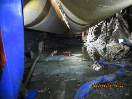
The execution of the crossing An access tunnel was excavated by blasting into the river-tunnel, in order to transport equipment and workers in, in addition of establishing a rig area close to the crossings. Before the work inside the river started, the river tunnel was inspected, surveyed and additional rock support were installed. A subcontractor was hired with expertise on underwater constructions, and divers transported steel pipes up the river from the tunnel entrance by the harbor. To enable the transport of the pipes, the water level had to be increased by curbing the river. Two steel pipes with 2 m diameter were placed next to each other to ensure the capacity of the river throughout the construction period, see figure 11-6. At the entrance and the exit of the pipes, sandbags were used to build dam walls to guide the water into the pipes and expose the invert. To keep the water level low underneath the steel pipes, pumps were continuously pumping out the remaining water, see figure 11-7. The divers used boats to transport all the necessary equipment in and out from the pipes. The steel reinforcement was transported in, and then placed at the bottom of the river-tunnel, and pipes were installed along the wall to pump the concrete to the crossing areas.
The reinforcement of the crossing areas was done in two rounds. First the area crossing the inbound and outbound Follo Line tunnels was reinforced and casted. Then the dam walls were torn down and the pipes moved downstream, above the area crossing the inbound Østfold Line. The dam walls were rebuilt, and the water removed from under the pipes. After the invert was reinforced and casted, the pipes were removed and transported out. The capacity of the river was reset, and a successful crossing of the three railway tunnels could be performed. The works in the Alna River started in January 2017 and finalized in March 2018.
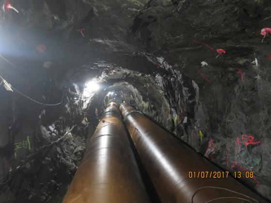
Figure 11-6: The steel pipes installed above the crossing with Inbound and Outbound Follo Line. Figure 11-7: The exposed invert of the Alna River tunnel under the steel pipes.
Challenges Even though the alternative solution saved both cost and time, there were several challenges during the crossing of the river. One of the most time consuming aspects were the periods with heavy rain. When raining, the water level became too high and the water flow too strong to continue to work in the river. Sometimes this caused hours of waiting, sometimes days. In addition, during periods when the capacity of the nearby water treatment plant exceeded its limits, the overflow went directly into the Alna River. This caused illness among the divers. Simultaneously with the work in the river, blasting took place in other parts of the tunnel system. Because of the age and low level of rock support in the river tunnel, the divers had to evacuate to the access tunnel when blasting was performed in some of the tunnels nearby. This required good radio communication and lead to more waiting time.
Because of the low overburden between the railway tunnels and the Alna River tunnel it was necessary to install heavy rock support; reinforced shotcrete, spiling, lattice girder, vertical bolts, and watertight concrete lining. The excavation was done by drill and split to avoid any vibrations.
The distance between the two Follo Line tunnels and the Alna River tunnel was approximately 5 m, and the crossings were successfully performed, without any unforeseen events. The distance between the crown of the inbound Østfold Line tunnel and the bottom of the river tunnel was estimated to be approximately 0.7 m. When the reduced profile of the inbound Østfold Line tunnel was excavated to the full profile, around 5 m2 of the concrete plate on the bottom om the river tunnel was exposed, and there were some leakages into the tunnel below. After installation of the rock support, the leakages were stopped by careful grouting. After casting the watertight lining, no further leakages into the railway tunnel were observed. The Alna River tunnel was restored to its previous capacity and the crossing was deemed successful.

Figure 11-8: The exposed concrete plate from below. Figure 11-9: Rock support under the Alna River tunnel.

Crossing under the E6 Ekeberg tunnel
Crossing under the E6 Ekeberg tunnel was one of the most critical crossings due to the low overburden, a fracture zone and strict vibration restrictions. Each day, approximately 70 000 vehicles pass through the E6 Ekeberg tunnel. This is one of the main roads in and out of Oslo, and it was a clear requirement not to disturb the traffic during the construction of the three tunnels.
Before the excavation was allowed to start, the Norwegian Public Roads Administration had several requirements for this crossing. It was installed a comprehensive vibration surveillance system and planned for regular inspections in the road tunnel before and throughout the construction period. In addition, the stress situation around the tunnels were carefully monitored by doorstoppers and extensometers, installed both in the railway tunnel and in the road tunnel. This is illustrated in figure 11-10. Because of the strict vibration limitations, the excavation was done by drill and split.

Figure 11-10: Stress surveillance at the crossing with E6 Ekeberg tunnel (SINTEF).
The overburden between the crown in the inbound Østfold Line and the ditch in the road tunnel is approximately 3.5 m. In addition, a known fracture zone crossed through the tunnel within the same area as the overburden was low. Based on the mappings from the former excavation of the road tunnel, the location of this fracture zone was known at an early phase of the planning. However, to get the exact location of the zone, core drillings were performed before the start of the crossing. Because of the low overburden and the fracture zone, it was decided to install heavy rock support for the inbound Østfold Line tunnel through the entire crossing zone under the Ekeberg tunnel, see figure 11-11. Using drill and split as the excavation method, with only 0,5 m progress every day, ensured a safe and controlled crossing and installation of the rock support. The rock support in the crossing area consisted of systematic bolting, reinforced shotcrete, 8 m spiling, vertical bolts and lattice girders covered by shotcrete. Water and frost protection consisted of a draining layer, sheet membrane and casted lining. During the drilling of control holes in the fracture zone, some water leakages were discovered, which was stopped by pre-grouting with silica-gel. Because of the mitigation measures taken and the careful monitoring before and during the excavation, the crossings were successfully completed without any unforeseen incidents or damage to the existing infrastructure.
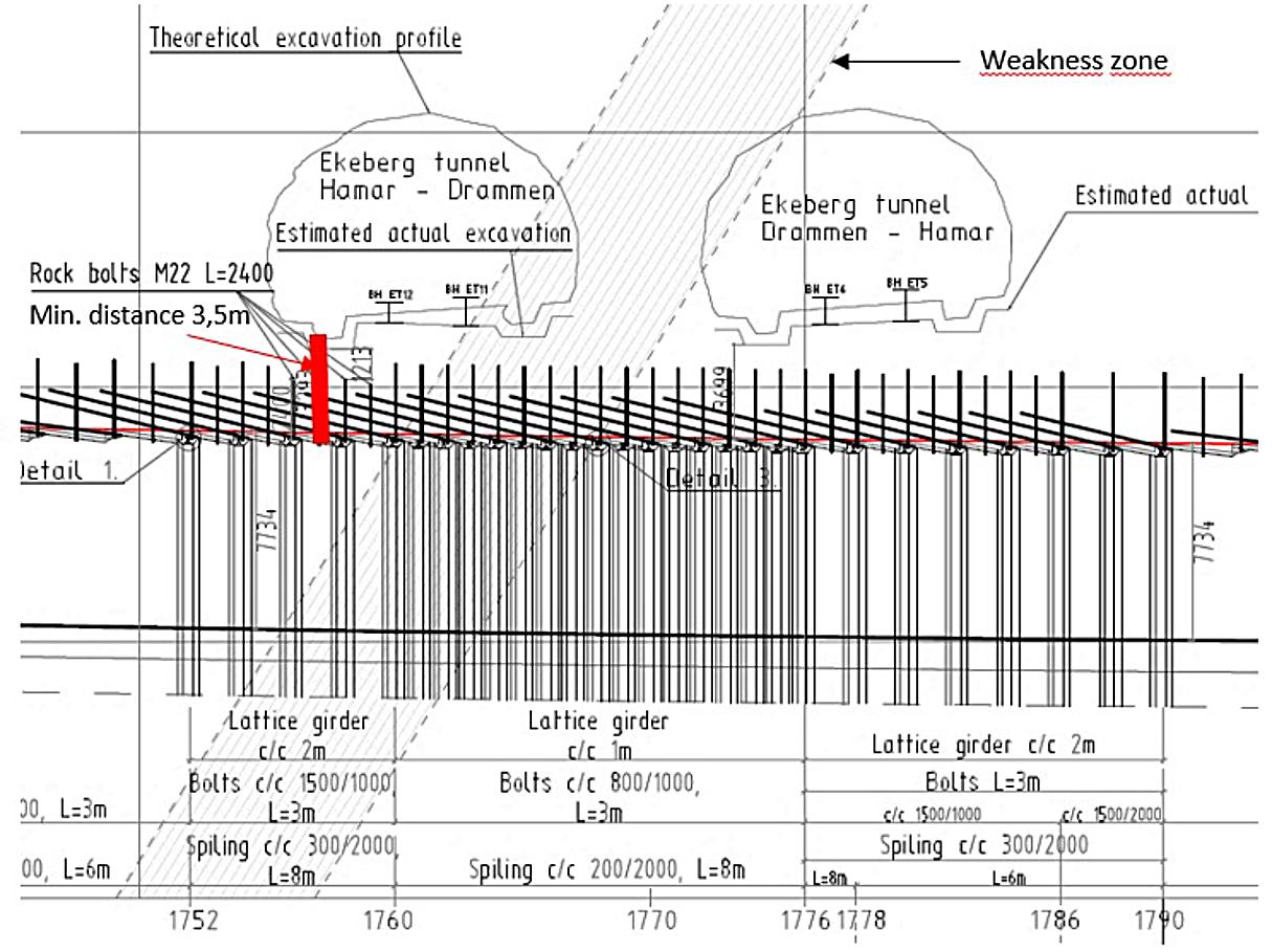
Figure 11-11: Overview of the crossing of the inbound Østfold Line and E6 Ekeberg tunnel. The drawing shows the smallest distance between the ditch and the crown (3.5 m), the estimated location of the fracture-zone and the heavy rock support.
Crossing close to the caverns for storage of petroleum products
In connection to the caverns for storage of petroleum products, there is a large system of interconnected infrastructure. The caverns were built as unlined rock caverns during the1960’s and 1970’s. They use the ground water pressure to keep the petroleum products in the caverns. In addition, there are access tunnels, escape tunnels, ventilation systems and other types of surveillance systems. This whole system is very sensitive to vibrations, and drill and split was planned for the excavation of the railway tunnels through the most critical sections. The crossing took place in two areas.
(1) Crossing between the inbound Østfold Line and maintenance and escape tunnels
(2) Crossing between the Follo Line tunnels and the petroleum caverns. Crossing between the Inbound Østfold Line and the maintenance and escape tunnels. The inbound Østfold Line tunnel crosses several maintenance tunnels and one escape tunnel from the petroleum storage caverns (figure 11-12). Before the startup of the excavation, Bane NOR and the owners of the caverns made a careful assessment of the cavern system. One of the most sensitive parts was the ventilation system. By upgrading this, the tolerance for vibrations was increased. After the upgrade, the scope of drill and split could in some areas be replaced by careful blasting, which increased the progress significantly. The vibrations were carefully monitored throughout the excavation. If they came close to the limits, then the excavation was done by drill and split instead. By carefully monitoring the vibrations and adjusting the excavation method, the crossing was successful, without any damage to the existing infrastructure
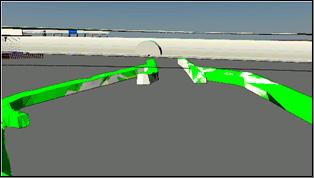
Figure 11-12: Crossing between the inbound Østfold Line (grey) and the escape tunnels from the petroleum storage caverns (green).
Crossing of the Follo Line tunnels and the petroleum caverns. The two Follo Line tunnels cross the petroleum storage caverns with very small distances. Because of the sensitive nature of the infrastructure and the small distances, the vibration limitations were strict, and the tunnels were excavated by a combination of drill and split and careful blasting. Because of the possible leakages from the petroleum caverns, a continuous gas monitoring system was installed. In addition, the closest caverns were emptied in the most critical period when the excavation took place close to the storage area.
The greatest concern was still that the groundwater around the petroleum storage caverns would drain or be lowered due to the tunnel excavation. To reduce this risk, several water curtain screens were drilled above the caverns, and water continuously pumped into the rock to maintain the water level. In addition, the groundwater level was carefully monitored daily. The water curtain was maintained until the excavation was finished and the lining installed. In the section above the caverns a gas tight membrane and full profile lining cast was used to keep the groundwater at the required level. The monitoring of the groundwater was continued for a while after the lining had been installed, and no changes of the water level, caused by the tunnel excavation, were observed.
Crossing and culvert design of the escape tunnel from the petroleum caverns
North of the contract boundary between the EPC TBM and EPC D&B, the two Follo Line tunnels would cross right through the escape tunnel from the petroleum storage caverns. As described earlier, it was a requirement that the escape tunnel should be in operation 24/7 throughout the entire constructions period. To fulfill this, a by-pass had to be built under the new railway tunnels, with stairs to connect from both sides to the existing escape tunnel. See figure 11-13. In the design phase, it was considered easier to build the by-pass from a drill and blast tunnel, than from a TBM excavated tunnel, therefore the boundary line was set just before the escape tunnel.
The escape tunnel is approximately 2 km long and has a cross section around 8 m2. The by-pass was built below the future railway tunnels. At each end of the by-pass, this was connected to the existing escape tunnel.
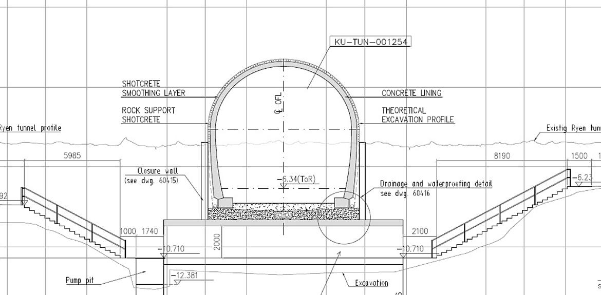
Figure 11-13: Culvert design for the escape tunnel below the Outbound Follo Line tunnel.
The crossing of the new railway tunnels with the escape tunnel that had been replaced, was performed by careful blasting. During this crossing, old

Figure 11-14: Careful blasting at the crossing. explosives were discovered in the old escape tunnel, and had to be removed carefully before the work could continue.
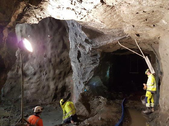
Figure 11-15: Profile of the tunnel at 8m2 .
Establishing the southern portal for the inbound Østfold Line at Sydhavna
The Inbound Østfold Line exits the tunnel section and is connected to the existing track on the Østfold line at Sydhavna. The portal was to be constructed in a cramped area, underneath the road E18 Mosseveien and between the rock surface and the existing Østfold Line track. Below the railway is the entrance tunnel to the Ekeberg storage halls. Because of the low overburden, strict vibration limitations and poor rock quality, the excavation of the tunnel was performed by drill and split, and heavy rock support was installed. Because of the small distance to the road, the breakthrough could not be completed until the portal was completed. The design of the portal was carefully considered by both Bane NOR and Norwegian Public Roads Administration before construction. The South Portal Before the construction of the portal, an access road was blasted and dug out up to the rig area (figure 11-16). The access tunnel to the Ekeberg storage halls were used at the access point. After reaching the site, a wall was built between the construction site and the railway track close by, so that the construction could continue without disturbing the railway traffic. To strengthen the rock between the portal of the inbound Østfold Line and the road, rock support was installed, both bolts and shotcrete were used (figure 11-17). In addition, the ventilation tower used by the Ekeberg storage hall had to be torn down and rebuilt in another location, to avoid conflict with the new railway tracks.
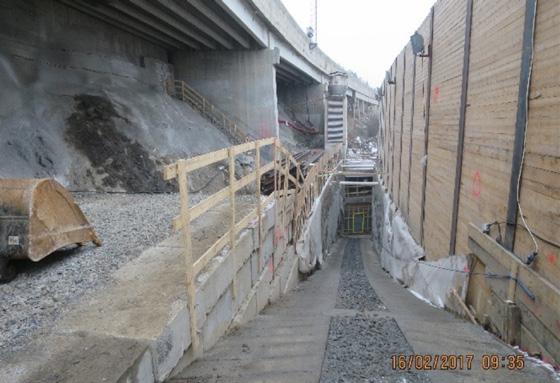
Figure 11-16: Access to the South Portal. Figure 11-17: Rock support under the E18.

To excavate safely under the E18 Mosseveien the rock below the road was reinforced by core drilling and installing H-beams. Afterwards, the beams were grouted and extended out into the portal (figure 11-18). The outer wall of the portal was reinforced and casted up under the H-beams and then the beams were casted into the roof of the portal. After finalizing the portal, the last few meters of tunnel were excavated by drill and split. Heavy rock support was installed, then the lining was casted. Throughout the construction, the vibrations were carefully monitored, and the construction site was regularly inspected by the Norwegian Public Roads Administration. The portal was completed without any damages to the nearby infrastructure (figure 11-19).
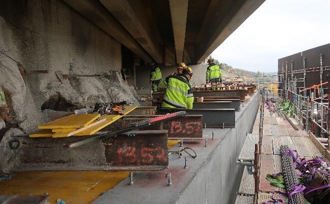
Figure 11-18: Extension of the H-beam.
Crossing between the two sewage tunnels
Before crossing with the TBMs between the sewage tunnels Kværner and Midtgardsormen, some preparations had been made. During the construction of the Midtgardsormen tunnel, they reinforced the section of the crossing with rebars in the crown of the sewage tunnel and a concrete lining. The distance between the Follo line tunnel and the sewage tunnel was approximately 0.5 m. Then it was prepared for a safe crossing by the TBMs above the Midtgardsormen tunnel.
To avoid any leakages from the Kværner tunnel into the Follo line tunnels, the sewage was led from the Kværner tunnel and into the Midtgardsormen tunnel before the crossing with the TBMs took place. This was done by raise drilling from the surface, down

Figure 11-19: South Portal completed.
into the Kværner tunnel and further down into the Midtgardsormen upstream of the crossing-point with the Follo Line tunnels. Then, the excavation of the two Follo Line tunnels could be performed just beneath a dry Kværner tunnel. As soon as the lining was installed in the two Follo Line tunnels, the connection between the two sewage tunnels was closed, and the sewage could continue to flow through the Kværner tunnel.
Unforeseen challenges Before the first crossing with the TBM and the Midtgardsormen tunnel, the TBM stopped above the crossing point for inspection of the reinforced lining below. Surprisingly, the concrete was missing, and only the rebar was present in an 18 m2 section.


Figure 11-20: The missing concrete in the crown of Midtgardsormen.
This resulted in a few days stop for casting the reinforced lining in the crown of the Midtgardsormen tunnel before the machine could pass above. When crossing the Midtgardsormen with the second tunnel boring machine, the lining was completed as expected, and there were no further surprises. The crossing was completed within a few hours.
Lessons learned
All the crossings of the new railway tunnels, at the Follo Line project, with existing infrastructure, has been completed without damaging any nearby objects. The lessons learned have been that good knowledge of all the existing infrastructure is vital and all the necessary preparations must be completed before starting the crossing. Cooperation and communication with the owners of the infrastructure was essential to the success. One of the most important tools for both the planning of the performance as well as for communication with the owners, was an up-to date 3D-model with all the objects based on updated surveys. It was also important that both client and contractor had contingency plans to handle any unforeseen events in case of surprises.
The well planned preparations and the careful execution of the tunnel excavation resulted in a successful performance of the crossing of the sensitive infrastructure. No damages occurred.