18 minute read
10 Tailormade TBMs for boring in hard rock

from Tunnelling in the Follo Line Project - NFF Norwegian Tunnelling Society publication no 29
by TunnelTalk

Arnulf M. Hansen, Bane NOR Amund Bruland, NTNU Fredrikke S.G. Syversen, Bane NOR Steinar Johannessen, Bane NOR
Introduction
Advertisement
There are quite a few examples of TBM projects that have suffered low progress and high cost due to improper design of TBM and cutters. Dealing with massive, homogeneous, abrasive, and extreme hard rock with UCS in the range of 100-300 MPa, would demand a specific design of the TBMs and the cutters. This chapter will focus on design parameters that had to be considered in specifying the TBMs for hard and massive rock conditions. This included design of cutters, cutterhead, main bearing assembly and the rest of the TBM system as well. Based upon geological investigations and extensive testing of rock samples, the Project owner set strict requirements to the TBM design already in the invitation to tender.
TBM tunnelling in hard rock conditions is associated with high risk related to advance rate and cutter consumption, and TBM design based on expected rock mass properties is a crucial part of the frontend risk management in such projects. In order to cope with extreme hard rock challenges anticipated on the Follo Line project, a robust TBM design was imperative. The general thinking should be that the geological pre-investigations cannot reveal the complete picture of the rock mass properties, hence, TBM design should at least match the expected geological conditions.
The general understanding of rock breaking under a disc cutter is shown in figure 10-1.
During rock breaking under a disc cutter, efficiency is characterized by the size and shape of the largest chips, and by the amount of fines produced. For a given rock mass, rock-breaking efficiency may be increased by increasing the applied cutter thrust force (i.e., the contact stress under the cutter ring) and/or increasing the number of cutters on the cutterhead (i.e., decreasing the average cutter spacing).
Figure 10-1: Rock breaking under a disc cutter (Bruland 1998).
Efficient boring in extremely hard rock conditions is characterized by very high average cutter forces, cutter peak forces, cutterhead vibration levels and cutter ring wear. The TBM design should be based on these experiences.
Hard rock TBM design
Based on field data from more than 250 km of hard rock tunnels, the NTNU, Norwegian University of Science and Technology, has derived some important design principles for hard rock TBMs (Bruland 1998) that were implemented in TBM design for the Follo Line project.
For individual disc cutters, the very high average and peak cutter forces have a strong impact on the design. The trend has been to increase the cutter bearing size and the cutter ring diameter in order to apply higher cutter thrust. Since 1985, standard cutter diameter for hard rock conditions has been 19in, with 20in being the possible next step.
The design of the cutter ring itself relies very much on the current steel material technology. A constant cross section type is used, with cutter ring edge width varying from 15mm to 25mm. The necessary edge width is generally larger in the outer part of the cutterhead than in the inner part. A cutter in the outer part of a cutterhead will have higher rolling velocity and is exposed to higher peak loads than a cutter in the inner part of the cutterhead. Hence, a wider ring is needed to avoid destructive wear in these outer positions.
The number and layout pattern of the disc cutters on the cutterhead plays an important role in hard rock conditions. Figure 10-1 indicates that the spacing between adjacent cutter tracks influences the necessary thrust to break large chips - the larger the spacing, the higher the necessary thrust. The second fact to consider, is that the rock breaking work increases with the square of the radius from the centre of the tunnel face and outwards. Hence, spacing between cutter tracks must decrease towards the gauge.
When considering rock breaking efficiency and cutter wear only, the ideal cutter layout pattern would be to place all cutters along one diameter line of the cutterhead, for example, with cutters in tracks one, three, five etc. on the left-hand radius and cutters in tracks two, four, six etc. on the right-hand radius. However, such a design would generate extremely high and unbalanced forces on the cutterhead structure and on the main bearing. The seemingly best alternative is to apply the same alternating cutter placement along the two arms of a double spiral starting in the cutterhead centre.

Figure 10-2: Cross sections of chips collected during a penetration test. Increasing rock breaking efficiency from upper to lower chip.
The general experience is that the total number of cutters on a cutterhead intended for boring in extremely hard rock conditions, should correspond to an average cutter spacing of approximately 70 mm over the cutterhead. When extremely hard rock conditions are expected, one must consider having more cutters on the cutterhead in exchange for smaller openings for muck removal.
Due to very high average and peak cutter forces, the main bearing will have to respond to a very high and unbalanced load situation. Considering the total rock-breaking work of the tunnel face, half of the work will be outside 0.7 of the cutterhead radius. Also, the cutter peak loads will increase towards the gauge due to the higher rolling velocity of the cutters and the curvature of the cutterhead structure. Hence, the main bearing diameter should be in the range of 0.7 of the cutterhead diameter.
Efficient boring in hard rock conditions is associated with strong vibrations originating from the high peak loads of the rock breaking process itself. These vibrations will put large strain to the cutterhead structure in general and on the cutter housings in particular. The simple solution is to add structural strength and weight to the cutterhead using steel.
One more item to consider is the stiffness of the cutterhead structure and the cutterhead thrust system. The stiffness of the cutterhead structure will be improved by more steel in the cutterhead structure. The recommendation for the thrust system is to increase the hydraulic stiffness by increasing the

Figure 10-3: Normal force recorded during linear cutting tests. Except from the hydraulic stiffness, cutting parameters are identical (Snowdon et al., 1983).
Figure 10-4: Face mapping on TBM S-980. The rock at the face consists of gneiss with lenses of amphibolite.
diameter of the thrust cylinders and/or increasing the number of thrust cylinders.
Geological conditions
From studies carried out, the rocks along the tunnel alignment consist of Precambrian gneisses with bands and lenses of amphibolite and pegmatite with several intrusions. The rock mass is quite homogenous and competent with moderate jointing. The demanding massive, hard, tough, and abrasive rocks have a UCS in the range of 100MPa to 300MPa. This is described in more detail in Chapter 3 “Preconstruction planning and geological conditions” The expected advance rate according to the NTNU Prediction model (Bruland, 1998) was 15.6m per day.
Role of the project owner
The Follo Line project, developed by Bane NOR under commission from the Ministry of Transport and Communications, is a pilot project for a new contract model as well as new tunnel excavation methods for Norwegian railway tunnels. The use of EPC contracts, the use of drill and blast in combination with drill & split and the use of TBMs pave the way for innovation and knowledge upgrading. The project construction includes five separate EPC contracts and one contract for the signal system of which the EPC TBM contract is the largest.
Bane NOR was the owner of all the TBM equipment at site until breakthrough. The contractor was then obliged to execute the buy-back. The background

for this contractual arrangement was, should the contractor go bankruptcy during the tunnel construction period, then the equipment could be transferred to a new contractor.
The success of the Follo Line TBM tunnel project was highly dependent on the performance of the four TBMs operating from the centrally located access point at Åsland. In order to cope with the hard rock challenges to be encountered at the project, the most robust TBM design was a must. For hard rock tunnel boring, a stiff cutterhead and a large diameter and high-capacity main bearing, capable to withstand extreme eccentric cutterhead loads, is crucial for the tunnel boring operation.
TBM Requirements included in Invitation to Tender (ITT)
• Hard rock double shield TBM • Detailed specifications and design drawings prior to commencement of manufacture to be made available to client • All parts new and traceable • Sealable ports in shield • Core drilling system • Retractable cutterhead • Back-loading cutters • Cutter monitoring system • Main bearing L10 life: min. 15 000 hours (in compliance with ITA-tech guidelines) • Fully automatic guidance system • Automated electronic data recording system – transmittal to surface in real time and available to client at any time • Gas detection system • 12 bar water pressure resistance – static • Water filling of excavation chamber • Probing and pre-grouting drilling • Equipment for MWD • Mapping of probe holes by tele-viewer • Number of grouting ports • Number of drilling rigs • None-flammable conveyor belts • Automatic fire detection and suppression system • Refuge chambers in compliance with ITA
Guidelines -24 hours stand-up time
Additionally, there were another 40 requirements for the TBM and Backup system, Scope of work, TBM excavation and support, and OH&S.
Four of six pre-qualified international joint ventures submitted bids on the TBM section of the Follo Line tunnel. The international bidders had no or limited experience from tunnel boring in hard and tough rock similar to Norwegian bedrock consisting of gneiss and granites.

Figure 10-5: Launching of TBM S-982 (photo: AccionaGhella Joint Venture).
The Follo Line organization had personnel with own experience from hard rock tunnel boring in Norway and abroad and who had been cooperating through many years with the Norwegian University of Science and Technology (NTNU), a world leading institution when it comes to hard rock tunnel boring. Therefore, the Follo Line organization was capable to, -, evaluate the technical specifications proposed in the tenders and make their own judgements.
In the original tender, the winning contractor AGJV offered TBMs with technical specification well within the invitation to tender requirements. In the revised tender, the TBM supplier was changed, and some technical specifications were changed prior to signing the contract to further improve the final design of the TBMs.
Bane NOR played a pro-active role in upgrading of the TBM technical specifications during the final design of the four 9.96 m diameter double shield TBMs for the Follo Line tunnel project (Figure 10-5). This includes improved cutterhead and main drive design which resulted in increased stiffness of the cutterhead and a larger-diameter main bearing, with extended L10 life.
Other important design criteria for TBM boring in hard to extreme rock conditions that were focused on as well, were:
• The Main bearing L10 lifetime was extended from 15,000 hours to min. 20,000 hours • The weight of the cutterhead was increased from 230 to 265 metric ton
• The number of cutting discs were increased from 66 to 71 (70 tracks – the two outermost gage cutters are double tracking) thus resulting in reduced average cutter spacing to 71 mm. • The cutterhead is equipped with 19in cutters, but the cutter housings are prepared for use of 20in cutters • The inner and outer main bearing seal arrangement was modified to include pressurized seal rings for 12 bar water pressure resistance during emergency sealing of the TBM shield. • The size of the Main bearing was increased from 6.0 m to 6.6 m diameter
Details
TBM cutting diameter
Cutter size
Number of disc cutters
Load per cutter ring 9,960 mm with new cutters
19-inch wedge lock, back-loading
4 center (x 2 discs) + 48 face + 15 gage = 71 cutting discs
315 kN
Max. recommended CH load 71 x 315 = 22,365 kN
Weight of Cutterhead 265 metric ton equipped with cutters
Cutter monitoring system 5 cutter positions monitored (positions: 42, 44, 46, 48 and 50)
Cutterhead (CH) power 13 each VFD motors x 350 kW = 4 550 kW
Total power installed approx. 6900 kW
CH rotational speed 0 – 6.06 rpm
Nominal torque
Max. overload torque
Main Bearing (MB)
Main bearing lifetime
Main Bearing Seals 11,115 kNm @ 3.67 rpm
16,672 kNm @ 3.67 rpm
3 axis roller bearing, 6,600 mm OD
> 20 000 hours according to ITA-tech guidelines
Inner and outer sealing system, each: 3 lip seals + activatable seal ring for 12 bar static water pressure resistance
Total length, TBM + Backup approx. 150 meters
Total shield length 14,415 mm
Total weight, TBM + BU approx. 2,400 metric ton
Probe Drilling Equipment: Two drill rigs with rod adding system for drilling up to 35 m long holes for probing and pre-grouting through 38 ports in gripper shield with 11-degree angle to tunnel axis and or through 8 openings in the cutterhead.
Table 10-1: Brief final revised TBM specification
Bane NOR requested a third party-verification of the Main bearing (MB) L10 life calculation for the proposed 6,000 mm diameter main bearing according to ITA-tech Report No. 1 – April 2013, and for the design of the cutterhead (CH). Babendererde Engineers of Germany performed a this verification of the main bearing L10 life calculation for the proposed 6,000 mm main bearing and proposed some design changes to the cutterhead.
In order to further minimize the risk of main bearing failures during TBM tunnel construction, the Follo Line management entered into an agreement with the contractor to enlarge the diameter of the MB to 6,600 mm OD, which gives a MB:TBM diameter ratio of 0.66.
Logistics
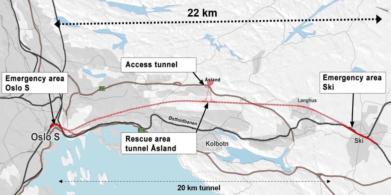
Two central TBM launching locations
Approx. 18.5 km of the 20 km long tunnel sections was excavated by four TBMs, operating from one centrally located access point at Åsland, close to the main road E6 and with a limited number of neighbors in proximity to the rig area (Figure 10-6 and Figure 10-7). Two access tunnels, each approximately 1 km long, had been excavated from the main rig area and down to the location for the future railway tunnels. Additional auxiliary tunnels and two large assembly chambers were constructed utilizing conventional drill and blast techniques as a preparation for the assembly and operation of the TBMs.

Figure 10-6: The TBMs were assembled in two centrally located large caverns.
The first of the four Herrenknecht 9.96 m diameter Double Shield TBMs started the boring operation activities in September 2016 and by the end of the year all of the machines were in operation. The TBM excavation was expected to be completed by the end of 2018/ beginning of 2019. Two TBMs were boring in the northward direction toward Oslo Central Station, and two TBMs were working in the southward direction toward the city of Ski, where the bored tunnels were connected to a cut- and cover section.
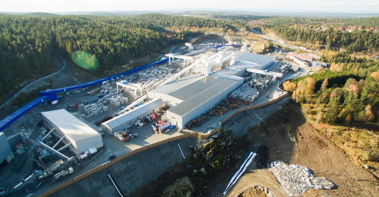
The location at Åsland and the opportunities to develop a compact site arrangement, including all the necessary operations for the production of the 18.5 km long twin tunnel, provided great environmental benefits compared to excavation by drill and blast from several different access points. Continuous conveyor belts, transporting the excavated material from the tunnels, have reduced the number of vehicle and traffic movements.
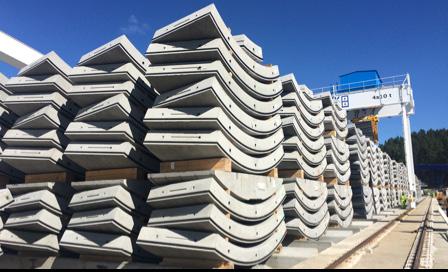
Water-tight segmental lining
Inside the tunnel, gasketed pre-cast concrete segments were installed in a closed ring to ensure rock support, as well as protection from water leaking into the tunnel. In addition, invert segments were installed inside the segment rings.
The production of these elements took place at Åsland site and approximately 10% to 15% of the TBM spoil was intended to be reused in the pro-

Figure 10-7: An overview of the centrally located rig area at Åsland with the conveyor belt (blue), segment factory, offices, and accommodation for the workers.
duction of these concrete segments. However, due to content of pyrrhotite in the TBM spoil, external material had to be used. This is described in more detail in chapter 9 “Use of the tunnel spoil”.
Launching all four TBMs from Åsland, also enabled reuse of spoil for potential future residential developments within the area. This reduced the volume of traffic on public roads and pollution from vehicles.
Transport in the tunnels
Multipurpose Service Vehicles (MSV) were used for transportation of concrete segments and other materials from the storage area at the surface directly to the TBM headings. The shift-crews were as well, transported to/from the TBMs by use of MSVs.
The grout, both component A and component B, for filling the annulus gap between segment rings and tunnel surface was transported through pipelines from the grout plant at surface all the way to the TBM backup system.
Experiences
Rate of penetration and Advance rates
Rate of penetration and advance rates are given in respectable table 10-2 and table 10-3 below. The advance rates depended on whether pre-grouting had to be performed or not. The weekly production during weeks without pre-grouting could be more than 150 meters, but it could be reduced to approximately 1/3 in weeks with up to three rounds with pre-grouting.
Cutter experiences
As a rule of thumb, optimal tip width of the cutter rings for given rock conditions, should be as narrow as possible in order to obtain a good rate of penetration. However, the tip width of the ring should be sufficient to sustain the cutter loads needed to cut the rock efficiently without cutter-ring chipping or “mushrooming”.
For the Follo Line TBMs, the contractor tested cutter rings from the TBM-supplier, with different tip-widths, and it was assumed that a low Rockwell hardness of the ring, for hard rock tunnel boring, resulted in a “mushrooming” where the ring tip-width became so wide that penetration per cutterhead revolution was reduced. The contractor experienced, as well, a lot more cutter bearing failures than was expected.
Originally, the client expected the machines to be supplied with a cutter-monitoring system for all the cutter-positions. However, the machines were supplied with a monitoring system for only five cutterpositions, but for some reason they were never used. From the clients point of view, use of a monitoring system connected to all the cutter-positions would have given an early warning of cutter failure.
Based on previous experience from boring in similar Precambrian gneiss rocks in Norway, it was assumed that cutter life would in the range of 200 m3/ cutter change. These expectations were fulfilled.
From the clients point of view, the cutter thrust could have been utilized more efficient during the excavation in order to achieve an even better rate of penetration. A high degree of cutter-thrust is linked to the quality of cutters. Unfortunately, cutters from all suppliers with relevant experience from hard-rock
Average
Maximum
Minimum
ROP [mm/min]
33.46*
56.27
16.27
Table 10-2: Rate of penetration * Average achieved for gross total thrust force 21,071 kN Day
Week
Average [m] Highest [m]
15.mar 36.0
162.0
Month 381.2 583.0
Table 10-3: Average and best advance rates
TBM tunnelling, were not tested during the excavation of the tunnels.
Water pressure resistance
According to the TBM requirements the double shield machines were supposed to be designed to withstand 12 bar water pressure during emergency sealing of the TBMs.
One of the machines bored into a fracture zone, which gave heavy water leakage and the attempt of the contractor to seal off the TBM failed. The system was never used again.
Breakthroughs
The first of the four 9.96m double shield TBMs started boring operation activities in September 2016 and by the end of the year all of the machines were in operation. The two TBMs boring in the northward direction toward Oslo Central Station started the boring operation approx. five months ahead of schedule and broke through into an underground cavern in September 2018, still approx. five months ahead of schedule. In February 2019, the two TBMs working in the southward direction, toward the city of Ski, broke through into the cut-and-cover transition to a surface approach to the Ski railway station two months behind schedule. This was mainly due to pre-grouting in sensitive areas. In total, the entire TBM excavation were finalized within the contract schedule.
Conclusion
The success of the Follo Line TBM tunnel project was highly dependent on the performance of the four TBMs. In order to cope with the extreme hard rock challenges to be encountered at the project, the most robust TBM design was a must.
Bane NOR has played an active role in specifying the technical TBM requirements. Ultimately, TBM requirements included upgrading cutterhead and main drive design, resulting in increased stiffness of the cutterhead, reduced cutter spacing and a larger diameter main bearing with an extended L10 life.
AGJV supplied the TBMs for the Follo Line tunnel project in accordance with the final TBM specification requirements of Bane NOR.
At the end of all excavation in February 2019, these upgrades have proven to be justified. The TBMs performed as expected.
References
Bruland, A. 1998. Hard Rock Tunnel Boring. Doctoral Thesis, Norwegian University of Science and Technology, 1998:81.
Kalager, A. K. 2016. The Follo Line project-a large project that includes a complex excavation of the longest railway tunnel in Norway. Proc. World Tunnel Congress 2016, San Francisco.
Snowdon R.A., Ryley M.D, Temporal J. and Crabb G.I., 1983. The Effect of Hydraulic Stiffness on Tunnel Boring Machine Performance, Int. J. Rock Mech. Min. Sci. & Geomech. Abstr.,Vol. 20, No. 5.
Hansen, A. M., Bruland, A., Syversen, F. S. G., Johannessen, S. Tailor-made TBM design for boring in extreme hard rock conditions and examples from the Follo Line tunnel project. WTC 2017, Bergen.