Toyota Model 7HBW23 Service Manual
Section 6. Component Procedures Control Handle
Pos
Description
Pos
Description
Pos
Description
1
Screw
13
Electronic circuit board
25
Gasket
2
Keypad
14
Push button (option)
26
Signal button
3
Screw, 2 x M5 x 45 2 x M5 x 60
15
Top cover
27
Push button (option)
4
Handle
16
Display card
28
Wire, hold down
5
Cover, keypad (Optional)
17
Push button
29
Screw
6
Top plate
18
Emergency reverse button
30
Control switch
7
Screw
19
Push button (not used)
31
Sliding bearing
8
Bottom plate
20
Plate
32
Control stop
9
Grommet
21
Holder
33
Arm
10
Screw, M4 x 40
22
Push button, lift/lower
34
Axle
11
Spring
23
Arm
35
Spring holder
12
Lower cover
24
Display glass
36
Spring
Control Handle Disassembly 1. Remove screw [1], then unplug and remove the keypad [2]. 2. Remove the four screws [3] that secure the top cover assembly to the handle. Hold the top cover [15] firmly while removing screws. 3. Disconnect the cable connected to the electronic circuit board [13].
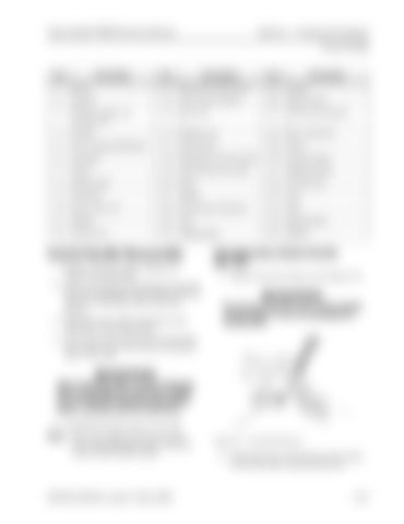
Changing Horn Button/Switch [26, 27] 1. Remove the horn button. See Figure 6-9.
Do not use excessive force when prying on the button or you can damage the locking tabs.
4. For access to the electronic circuit board [13], remove the screws [10] securing the lower cover [12].
Static electricity! Risk of static discharge that can damage the electronics. Make sure to take the necessary precautions before working with the electronics. 5. Carefully lift off the lower cover [12]. NOTE: Place your finger between the lower cover [12] and button [18] to hold the control switch [30] in place.
00700-CL340-05, Issued: 2 May 2005
Figure 6-9. Horn Button Removal
2. Disconnect the connection for the switch on the electronic circuit board [13].
6-15


