2 minute read
Section 3. Systems OverviewToyota Model

from Toyota Forklift 7HBW23 4,500 lb. Powered Pallet Walkie Service Manual SN 24501 and up - PD DOWNLOAD

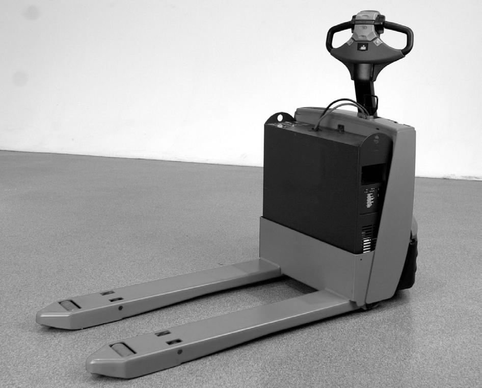
Truck Model Identification
Vehicle Specifications
Truck Model Identification 3-2
The total weight of the load must include the pallet and the container or the device holding the load.
Category
Maximum Load Capacity4,500 lb. (2,041 kg)
Upright Height50.8 in. (129.1 cm)
Overall Length (Handle Raised)up to 81.8 in. (207.8 cm)
Overall Width28.0 in. (711 mm)
Maximum Lift Height 8.65 in. (219.7 mm)
Regular Speed, Maximum3.9 mph (6.3 kph)
Stopping Distance6 ft. (1.83 m)
Battery Compartment Width7.8 or 9.0 in. (198 or 228 mm)
Battery Voltage24V
Minimum Battery Weight200 lb. (91 kg)
Maximum Battery Weight660 lb. (299 kg)
Truck Weight Without Battery800 lb. (362 kg)
Wheel: Drive10 x 5 in. Rubber
Wheel: Load3.25 x 5 in. Polyurethane (2)
00700-CL340-05, Issued: 2 May 2005
Special Tools
Programmable Maintenance Tool
Service Key
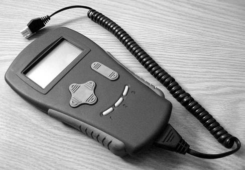
The optional Programmable Maintenance Tool (PMT) (P/N 00590-49981-71) permits you to test and diagnose the power amplifier in the truck. See Figure3-3.

The PMT is powered by the host power amplifier through the four-pin connector installed at the bottom of the power amplifier.
Use the optional Service Key (P/N00590-42683-71) directly on the truck to troubleshoot and program the truck service parameter settings. See “Parameters (P)” on page5-17.
Theory of Operation Truck Starting
To start the truck, the battery is plugged in, the Master Control ON/OFF switch is in the ON position, the PIN-key code is entered in the keypad, and the green ON (|) key pressed (or optional key switch is ON). See “Service Display” on page5-21.
Lift/Lower
The lift/lower system consists of an electrically operated hydraulic pump assembly and related components.
The hydraulic pump assembly consists of a positive displacement rotary gear pump with reservoir mounted to an adapter. A DC electric motor is mounted to the opposite side of the pump adapter. An adjustable relief valve, check valve, and a solenoid operated lowering valve are installed within the adapter.
With the forks elevated, the normally closed solenoid valve and the check valve prevent hydraulic fluid from returning to the reservoir.
Lift
When the battery is connected, the truck is ON, and the lift button pressed:
•a lift signal is detected via hall effect sensors, converted into the lift instruction, and transmitted via the Controller Area network (CAN) to the power amplifier.
•the lift pump contactor (K30) closes, applying B+ to the lift pump motor (M3) causing the lift pump to operate.
•hydraulic fluid is drawn into the lift pump.
•as the pump rotates, oil is forced out the pressure port through the lift hose to the lift cylinder. Oil cannot return to the reservoir because of the closed pressure relief valve and closed lowering solenoid valve.
•hydraulic pressure in the lift cylinder raises the forks.
•lift limit switch (S36) transmits a lift limit signal to the power amplifier which removes power to the lift motor when the forks reach a preset lift limit.
When the lift button is released:
•the pump contactor coil (K30) is de-energized. This stops the lift motor and pump. The forks are held in position by hydraulic fluid trapped in the cylinder by the check valve, the static position of the relief valve, and the closed lowering solenoid valve (Y10).
•the relief valve opens if the hydraulic pressure exceeds the preset limit.
Lower
When the battery is connected, the truck is ON, and the lower button is pressed:
•lower signal is detected via hall effect sensors, converted into the lower instruction, and transmitted via the CAN to the power amplifier.
•lowering solenoid valve (Y10) opens.
•hydraulic fluid in the lift cylinder returns to the hydraulic reservoir through the lowering valve and the flow control valve. The lowering speed is regulated by the flow control valve.
•the forks lower.
Direction/Speed Control
The following descriptions assume the battery is charged and connected, the truck is ON, and main contactor (K10) is energized.
Control Handle Positioning
When the control handle is in the full upright position, the parking brake is engaged. When the control handle is positioned from 6 to 46° of the full upright position, the brake disengages e