6 minute read
Toyota Model 7HBW23 Service ManualSection 6. Component Procedures Control Handle

from Toyota Forklift 7HBW23 4,500 lb. Powered Pallet Walkie Service Manual SN 24501 and up - PD DOWNLOAD
PosDescriptionPosDescriptionPosDescription
1Screw13Electronic circuit board25Gasket
Advertisement
2Keypad14Push button (option)26Signal button
3Screw, 2 x M5 x 452 x M5 x 60 15Top cover27Push button (option)
4Handle16Display card28Wire, hold down
5Cover, keypad (Optional)17Push button29Screw
6Top plate18Emergency reverse button30Control switch
7Screw19Push button (not used)31Sliding bearing
8Bottom plate20Plate32Control stop
9Grommet21Holder33Arm
10Screw, M4 x 4022Push button, lift/lower34Axle
11Spring23Arm35Spring holder
12Lower cover24Display glass36Spring
Control Handle Disassembly
1.Remove screw [1], then unplug and remove the keypad [2].
2.Remove the four screws [3] that secure the top cover assembly to the handle. Hold the top cover [15] firmly while removing screws.
3.Disconnect the cable connected to the electronic circuit board [13].
4.For access to the electronic circuit board [13], remove the screws [10] securing the lower cover [12].
Static electricity! Risk of static discharge that can damage the electronics. Make sure to take the necessary precautions before working with the electronics.
5.Carefully lift off the lower cover [12].
NOTE: Place your finger between the lower cover [12] and button [18] to hold the control switch [30] in place.
Changing Horn Button/Switch [26,27]
1.Remove the horn button. See Figure6-9.
Do not use excessive force when prying on the button or you can damage the locking tabs.
2.Disconnect the connection for the switch on the electronic circuit board [13].
00700-CL340-05, Issued: 2 May 20056-15
Control Handle
3.Press out the switch from its mounting in the top cover assembly.
Changing Lift/Lower Button [22]
1.Remove the button by placing a screwdriver in the hole [A]. See Figure6-10.
Control Handle Stem
NOTE: For replacement parts information refer to Parts Catalog.
Removal
1.Press the red OFF (O) key on the keypad. Disconnect the battery connector.
2.Remove the hex head cap screw securing the stem mount cover. See Figure6-12.
3.Disconnect the wiring harness connector and arm angle switch connections. See Figure6-13.

2.Unscrew the holder [21] so that the arm [23] comes loose.
Changing Push Button [19]
1.Press the push button sideways.
2.Insert a screwdriver and carefully pry the button loose. See Figure6-11.
3.Unscrew the button’s holder and arm.
Before removing the cap screws in the next step, make sure you are holding the handle. When the cap screws are removed, the handle will fall.
4.Remove the three Allen head cap screws located at the base of the control handle stem. See Figure6-14.
5.Carefully remove the control handle stem and mount.
Reassembly
1.During reassembly, make sure that the brake release cam assembly is in the correct position before installing.
2.Position the control handle mounting base on the pivot assembly.
3.Reinstall the three Allen head cap screws.
4.Thread the wiring harness through the handle base.
5.Reattach the control handle head unit if removed.
6.Reconnect the handle harness connector and arm angle switch connections. Install the cable ties in their original locations on the handle harness.
7.Install the control handle cover.
8.Connect the battery connector. Press the green ON (I) key on the keypad.
9.Test the operation of the truck.
00700-CL340-05, Issued: 2 May 20056-17
Horn (H1)
Horn (H1)
NOTE: For replacement parts information refer to Parts Catalog.
Removal
1.Press the red OFF (O) key on the keypad. Disconnect the battery connector.
2.Remove the tractor cover.
3.Disconnect the two wires from the horn. See Figure6-15.
4.Remove the horn mounting bolt.
Installation
1.Attach the horn to the electrical panel and tighten the mounting bolt.
2.Attach the two wires.
3.Reconnect the battery connector, press the green ON (I) key on the keypad, and test operation.
4.Press the red OFF (O) key on the keypad. Disconnect the battery connector.
5.Install the tractor cover.
6.Reconnect the battery connector.
Power Amplifier (A1)
NOTE: For replacement parts information refer to Parts Catalog.
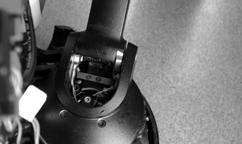
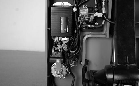
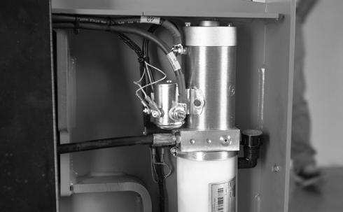
The power amplifier is installed in the tractor compartment. See Figure6-16.
Removal
1.Press the red OFF (O) key on the keypad and disconnect the battery connector.
2.Remove the tractor cover.
3.Discharge the capacitors in the power amplifier by connecting a load (such as a contactor coil or a horn) across the power amplifier’s B+ and B– terminals.
4.Push the locking tab and disconnect the J5 connector from the power amplifier. See Figure6-16.
5.Disconnect the three power cables (terminals B+, B– and M–) on the power amplifier. Do not stress the power cable connections. Disconnect wiring harness connectors (terminals F1 and F2).
6.Remove the three hex head cap screws securing the power amplifier to the electrical panel. Remove the power amplifier.
Installation
NOTE: All power amplifiers are preset to factory default specifications.
Do not open the power amplifier. Opening the power amplifier could damage it and will void the warranty.
Cleaning
1.Press the red OFF (O) key on the keypad and disconnect the battery connector.
2.Remove the tractor cover.
3.Discharge the capacitors in the power amplifier by connecting a load (such as a contactor coil) across the power amplifier’s B+ and B– terminals.
4.Clean the power amplifier with a moist rag. Let it dry before connecting the battery.
5.Make sure the power cable connections are tight. Do not stress the cable connections or put strain on internal components.
1.Secure the power amplifier to the electrical panel with the three previously removed hex head cap screws.
2.Reconnect the three power cables (terminals B+, B– and M–) on the power amplifier. Torque screws to 12 ft. lb. (16.3Nm) maximum. Do not stress the cable connections and put strain on internal components.
3.Connect the J5 connector and wiring harness connectors (terminals F1 and F2) to the power amplifier.
4.Connect the battery connector and press the green ON (I) key on the keypad.
5.Test operation of the truck.
6.Press the red OFF (O) key on the keypad.
7.Install the tractor cover.
Contactors
Contactors
NOTE: For replacement parts information refer to Parts Catalog.
Contactors (K10 and K30) control the transmission of battery power to the drive and lift motors.
Main Contactor (K10)
Removal
1.Press the red OFF (O) key on the keypad. Disconnect the battery connector.
2.Remove the tractor cover.
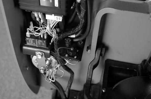
3.Disconnect the wires from the X and Y terminals on the contactor coils. See Figure6-17.

4.Remove the nuts securing the bus bar and cables to the contactor. Note the location for assembly later. See Figure6-17.
5.Remove the two screws holding the contactor assembly to the electrical panel.
4.Install the tractor cover.
5.Connect the battery connector. Press the green ON (I) key on the keypad.
6.Test the operation of the truck.
Lift Motor Contactor (K30)
Installation
1.Secure the contactor to the electrical panel with the two screws removed earlier.
2.Secure the bus bar and cable to the contactor with the nuts.
3.Connect the wires to the X and Y terminals.
See “Hydraulic Components” on page6-47.
Master Control Relay (K4)
Master Control Relay (K4)
The master control relay (K4) should be regularly tested for proper operation.
Inspection/Test
1.Remove the tractor cover.
2.With the battery connected, press the green ON (I) key on the keypad.
3.Use a voltmeter to check the voltage between wire #26 (terminal 4) and wire #24 (terminal 2).
The voltmeter should read approximately 24V.
4.Move the control handle down into the operating position. The voltmeter should now read 0V. If not, replace the master control relay.
Switches (General)
NOTE: For replacement parts information refer to Parts Catalog.
Refer to the schematic in the Appendix to identify the electrical circuit location of the switch. See “Schematics” on pageA-9.
Test/Inspection
Examine the switch for signs of arcing, overheating, discoloration, cracking, or other physical damage. Replace the switch if you see such damage.
To test a switch, isolate it from the electrical circuit. Do this by removing all the connections from the switch, making sure all wires are labeled and identified for later reconnection.
Use an ohmmeter set to a low resistance scale to measure the resistance across the switch. In the closed position, the switch must have a resistance of less than 1 ohm. In an open position, the switch must show a resistance greater than 10 megohms.
Master Control ON/OFF Switch
A Master Control ON/OFF switch (S21) is provided on the truck. In the OFF (O) position, battery power to all control functions is interrupted. In the ON (I) position, battery potential is provided to all control functions via the power amplifier. See Figure6-20.

Inspection
1.With the battery plugged in and the Master Control ON/OFF switch in the ON position, battery voltage B+ must be present on the two terminals of the switch.
2.Test the Master Control ON/OFF switch with an ohmmeter after disconnecting the battery and removing the wires from the switch terminals.
In the OFF position, the ohmmeter must read greater than 1 megohm, and in the ON position, the ohmmeter must read less than 1 ohm. If not, replace the switch.
Removal
1.Disconnect the battery connector.
2.Remove the tractor cover.
3.Disconnect the wires from the switch.
4.Remove the Master Control ON/OFF switch.
Installation
1.Install the new Master Control ON/OFF switch.
2.Connect the wires to the new Master Control ON/OFF switch terminals.
3.Reconnect the battery connector and verify operation.
4.Install the tractor cover.