2 minute read
Toyota Model 7HBW23 Service ManualSection 6. Component Procedures

from Toyota Forklift 7HBW23 4,500 lb. Powered Pallet Walkie Service Manual SN 24501 and up - PD DOWNLOAD
Wiring Harness
NOTE: For replacement parts information refer to Parts Catalog.
Advertisement
The wiring harness is designed to connect the electrical components of the pallet truck.
•Replace terminations with exposed wire visible at the connectors. Damaged terminations, exposed wires, or damaged connectors can cause operational failure of the truck
During troubleshooting and repairs, it is sometimes necessary to unmate a connector, move a harness, cut a cable tie, or remove the wire from a bracket. Note carefully the location of the wire and all protective or securing attachments before moving the harness.
After repair, return or replace all protective and/or securing hardware to its original condition. Protective materials are necessary to provide reliable performance of the interconnect system.
All wires in the harness are marked with a wire identification number. These numbers correspond to wire identification given in the schematic. All connectors are represented by “J” followed by a number. See “Schematics” on pageA-9.
Inspection
Whenever working on the truck, use care around wiring harnesses.
•Do not pull on wires
•Carefully mate and unmate all connectors
•Do not pry apart connectors with unspecified tools
•Examine and maintain any added materials used to dress or protect the wire. This includes spiral wrap, brackets, cable ties, fasteners, flexible conduit, and so forth.
•Examine harness wires for abrasions, scrapes, nicks in the wire, damage from overheating or burns, or other general insulation damage
In addition to the wire identification number printed every 1 to 1.5 in. (25.4 to 38.1 mm) on the wire, there is a wire marker at each termination. If the marker is missing or unreadable, remark the wire to permit easier identification.
NOTE: It is normal to find unused connectors for uninstalled options that have had heat shrink applied over them and have been strapped to the harness.
00700-CL340-05, Issued: 2 May 20056-11
Fuses
Fuses
NOTE: For replacement parts information refer to Parts Catalog.
Under extreme operating conditions, fuses (F50,F51) protect the electrical circuits and components from excessive current or voltage overloads.
Test/Inspection
Examine each fuse for signs of overheating, discoloration, cracking, or other physical damage. Replace the fuse if you find damage. See Figure6-7.
To test a fuse, remove it or isolate it from the electrical circuit. Do this by removing the fuse from the truck or by removing all the connections from one side of the fuse.
Use an ohmmeter set to Rx1 scale and measure the resistance across the fuse. The resistance must be less than 1 ohm.
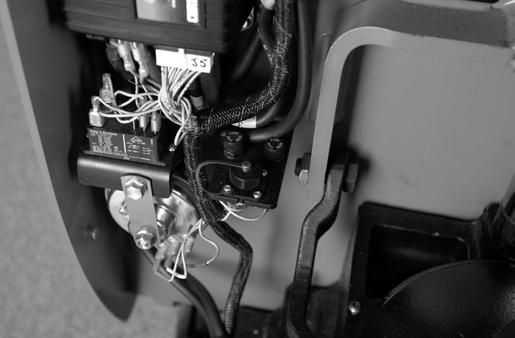
Circuit Breaker
NOTE: For replacement parts information refer to Parts Catalog.
Under extreme operating conditions the current demand on the battery may exceed the rating for the main circuit breaker (CB1) and force it open. This causes the truck to become inoperable until the circuit breaker automatically resets itself.
Test/Inspection
Examine the circuit breaker for signs of overheating, discoloration, or other physical damage. Replace the circuit breaker if you find damage. See Figure6-8.

To test a circuit breaker, remove the circuit breaker from the truck or isolate it from the electrical circuit by removing all the connections from one side. Let it cool (or reset itself).
Use an ohmmeter set to Rx1 scale and measure the resistance across the circuit breaker. The resistance must be less than 1 ohm.
00700-CL340-05, Issued: 2 May 20056-13
NOTE: For replacement parts information refer to Parts Catalog.