2 minute read
Section 6. Component ProceduresToyota Model 7HBW23 Service Manual Switches (General)

from Toyota Forklift 7HBW23 4,500 lb. Powered Pallet Walkie Service Manual SN 24501 and up - PD DOWNLOAD
Arm Angle Switches
The Arm Angle Switches (S24 and S25) determine brake activation and truck travel speed. Each switch is activated by the control handle position. The control handle must be positioned between 5° of vertical and 5° of horizontal in order for the switches to be closed, permitting travel. See “Arm Angle Switches” on page5-6.
Advertisement
Adjustment
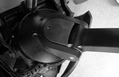
The arm angle switches are found at the base of the control handle stem. See Figure6-21.

1.Press the red OFF (O) key on the keypad. Disconnect the battery connector.
Use extreme care when the truck is jacked up. Keep hands and feet clear from vehicle while jacking the truck. After the truck is jacked, DO NOT rely on the jack alone to support the truck. For details, See “Jacking Safety” on page2-9.
2.Jack the truck and block the frame.
5.Slide the switch back in until the switch “clicks.” Move the switch out (approx. 1/32 in. [0.7 mm]) until it “clicks” again. Retighten the screws.
6.Make sure that the cam arm makes solid contact with the switch lever.
7.Verify that the switch “clicks” near the middle of the cam movement.
8.Switch S25 must operate within 5° of the full up or down handle position. Make sure the switch does not bottom out when fully compressed.
9.Install the stem mount cover. See Figure6-23.
3.Remove the stem mount cover.
4.Loosen the two screws holding the bracket on the stem mount. Slide the bracket out as far as possible. See Figure6-22.
10.Remove the blocks, connect the battery connector and press the green ON (I) key on the keypad.
11.Test the operation of the truck.
Removal
1.Lower the forks completely.
2.Press the red OFF (O) key on the keypad. Disconnect the battery connector.
3.Remove the stem mount cover.
4.Disconnect the wires on the switch.
5.Remove the mounting bracket from the stem mount.
6.Remove the screws holding the switch on the mounting bracket.
7.Remove the switch.
Installation
1.Mount the switch to the mounting bracket.
2.Connect the wires to the switch.
3.Install the mounting bracket.
4.Reconnect the battery connector. Press the green ON (I) key on the keypad.
5.Test drive the truck.
6.Adjust the switch if necessary.
7.Press the red OFF (O) key on the keypad. Disconnect the battery connector.
8.Install the stem mount cover.
9.Reconnect the battery connector.
Lift-Limit Switch
When the forks are fully raised, the lift-limit switch (S36) turns the hydraulic pump motor off. This keeps the pump from trying to extend the lift cylinder beyond its maximum travel. See Figure6-24.
Adjustment
1.Raise the forks until they reach their fully raised position. If the lift-limit switch does not shut the pump down when the lift cylinder reaches its upper limit, the relief valve on the hydraulic pump will make a high-pitched squeal, indicating that the relief valve is opening.
2.Press the red OFF (O) key on the keypad. Disconnect the battery connector.
3.Loosen the bolt and slide the switch bracket up or down to activate (cut power off) when the lift is 1/2 to 1 in. (13 to 25.4 mm) before the fully raised position.

4.Tighten the bolt.
5.Reconnect the battery connector. Press the green ON (I) key on the keypad. Lower the forks and then lift them until they reach their fully raised position. The lift-limit switch must cut power off to the pump when the lift cylinder reaches 1/2 to 1 in. (13 to 25.4 mm) before its fully raised position.