5 minute read
Section 5. TroubleshootingToyota Model 7HBW23 Service Manual

from Toyota Forklift 7HBW23 4,500 lb. Powered Pallet Walkie Service Manual SN 24501 and up - PD DOWNLOAD

Power Amplifier Fault Codes
Power Amplifier Fault Codes
An internal microcontroller automatically checks the function of the power amplifier. When this microcontroller detects a fault, the status LED on the bottom of the power amplifier flashes the appropriate code. See Table5-7. Under normal operation, the LED flashes a single flash (heartbeat) at approx. one flash every five seconds. A double flash indicates a fault has been detected by the microcontroller.
Table5-7 describes the fault codes that are shown on the status LED or read using the Programmable Maintenance Tool (PMT). See “Programmable Maintenance Tool (PMT)” on page5-26. Correct faults by following the “Troubleshooting Flowcharts” on page5-31.
2 ¤ power amplifier.
Open circuit at power amplifier +24Vdc logic input due to wire, fuse, or bad power amplifier.
Power amplifier does not have voltage at +24Vdc logic power supply input.
Power amplifier is not functioning correctly.
Normal “heartbeat”, everything is okay.
SHUNT FAULTSee “Code E202 - Power Amplifier Sensor Error” on page5-16.
HW FAILSAFE
See “Code E214 - Power Amplifier CAN Time-out” on page5-16 if ETAC is keyed ON.
Power amplifier is reporting that it is not receiving CAN messages from the ETAC, or that selftest failed. Otherwise, the controller is reporting it is not receiving CAN messages from the ETAC, which is normal when the truck is not turned ON.
M– SHORTEDSee “Code E201 - M– Error” on page5-16.
1, 4 ¤ ¤¤¤¤ SROBad power amplifier or ETAC.
2, 1 ¤¤ ¤ THROTTLE FAULT 1 Bad power amplifier.
2, 2 ¤¤ ¤¤ EMR REV WIRING
2, 3 ¤¤ ¤¤¤ HPDBad power amplifier or ETAC.
2, 4 ¤¤ ¤¤¤¤ THROTTLE FAULT 2Bad power amplifier.
Power amplifier is not setup or functioning properly.
3, 1 ¤¤¤ ¤ CONT COIL/FLD SHORTSee “Code E106 - Digital Output or Field Overcurrent” on page5-13.
3, 2¤¤¤ ¤¤MAIN CONT WELDEDBad power amplifier or ETAC. Power amplifier is not setup or functioning properly. 3, 3¤¤¤ ¤¤¤FIELD OPENSee “Code E200 - Field Open” on page5-15.
Table 5-7.
3, 4¤¤¤ ¤¤¤¤MISSING CONTACTORBad power amplifier or ETAC. Power amplifier is not setup or functioning properly.
4, 1¤¤¤¤ ¤LOW BATTERY VOLTAGESee “Code C41 - Battery Undervoltage Warning” on page5-11.
4, 2¤¤¤¤ ¤¤OVERVOLTAGESee “Code C42 - Battery Overvoltage Warning” on page5-11.
4, 3¤¤¤¤ ¤¤¤THERMAL CUTBACKSee “Code C43 - Power Amplifier Thermal Cutback” on page5-12.
4, 4 ¤¤¤¤ ¤¤¤¤ ANTI-TIEDOWNBad power amplifier or ETAC. Power amplifier is not setup or functioning properly.
Section 5. TroubleshootingToyota Model 7HBW23 Service Manual
Programmable Maintenance Tool (PMT)
Programmable Maintenance Tool (PMT)
The Main Menu is the starting point for the PMT. The main menu displays menu titles:
•Program (not used)
•Monitor
•Faults
•Functions
•Information
•Programmer Setup
If there are no entries within a Menu, then the Menu title will not be displayed.
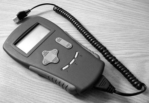
The optional Programmable Maintenance Tool (P/N 00590-49981-71) permits you to test and diagnose the power amplifier in this pallet truck.
The PMT is powered by the power amplifier through a four-pin connector at the bottom of the power amplifier. See Figure5-9.
The Menu Navigation Key moves the screen curser up or down through the Menu list (top or bottom arrow), and opens or closes Sub-Menus (right or left arrows).
The Data Inc/Key changes the value of the parameter indicated by the curser.
The Bookmark Keys allow you to quickly go back to your favorite selections without having to navigate back through the Menu.
•To select a position in the menu, hold a Bookmark Key down for three seconds until the bookmark set screen is displayed.
•To jump to a selected Bookmark position, press the appropriate Bookmark Key.
NOTE: The Bookmarks are not permanently stored in the PMT. They are cleared when the PMT is unplugged.
Monitor Mode
Real-time status information is displayed in the Monitor mode for various inputs, outputs, temperature, etc. This information can be helpful in troubleshooting many problems and is useful for checking out the operation of the controller during initial installation.
1.Press the red OFF (O) key on the keypad.
2.Remove the tractor cover.
3.Connect the PMT to the power amplifier. Wait for the PMT to “boot up” before proceeding to the next step.

4.Enter the PIN key code and press the green ON (I) key on the keypad or turn key switch ON.
5.Use the Menu Navigation Key to select Monitor.
6.Press the right arrow on the Menu Navigation Key to enter the sub-menu.
7.Use the Up and Down Button arrows to scroll through the sub-menu list of monitor variables.
8.Use the right arrow to select and view a single variable.
9.To change the value of the parameter use the Data Inc/Dec Key. Alternately, you can press the right arrow Menu Navigation Key once more and enter the detail screen. A bar graph appears as well as min and max data points. Change the parameter value by pressing the Data Inc/Dec Key. The new value is set as soon as the Data Inc/Dec Key is released.
To close a Monitor Menu, sub-menu, or detail screen, press the left arrow on the Navigation Key.
Faults Mode
In System Faults mode, currently active faults detected by the controller are displayed.
In Faults History mode, the controller’s diagnostic history file is displayed. This field includes a list of all faults observed and recorded by the controller since the history was last cleared.
NOTE: Each fault is listed only once, regardless of the number of times it occurred.
1.Press the red OFF (O) key on the keypad.
2.Remove the tractor cover.
3.Connect the PMT to the power amplifier. Wait for the PMT to “boot up” before proceeding to the next step.
4.Enter the PIN key code and press the green ON (I) key on the keypad or turn key switch ON.
5.To view the present status of the unit, use the Menu Navigation Key to select Faults -> System Faults
6.To access the log, use the Menu Navigation Key to select Faults -> Fault History.
7.Use the Up and Down Buttons arrows on the Menu Navigation Key to scroll through list of multiple faults.
Clear
After you have diagnosed and corrected the problem, clear the diagnostic history file. This permits the power amplifier to accumulate a new file of faults. By checking the new history file at a later date, you can easily determine whether the problem was completely fixed.
1.To clear the fault history of the unit, use the Menu Navigation Key to select Faults -> Clear Fault History.
2.Press the increment arrow (+) for yes and the decrement arrow (-) to cancel and not clear the fault history.
Table5-10 on page 5-28 lists possible messages you may see displayed when the PMT is operating in either System Faults or Fault History mode.
Information Mode
The Information Menu provides access to product information describing the basic revision level of the PMT.
To view, use the Menu Navigation Key to select Information in the Main Menu. Remember to press the right arrow to select a Menu. Press the left arrow to exit.
Programmer Mode
Programmer mode permits you to perform a variety of tasks.
1.Press the red OFF (O) key on the keypad.
2.Remove the tractor cover.
3.Connect the PMT to the power amplifier. Wait for the PMT to “boot up” before proceeding to the next step.
4.Enter the PIN key code and press the green ON (I) key on the keypad or turn key switch ON.
5.Use the Menu Navigation Key to select Programmer.