16 minute read
Section 6. Component ProceduresToyota Model 7HBW23 Service Manual Motors, General

from Toyota Forklift 7HBW23 4,500 lb. Powered Pallet Walkie Service Manual SN 24501 and up - PD DOWNLOAD

2.With the motor at room temperature, connect the leads of a digital ohmmeter between the individual circuits in the motor.
3.Observe the measurements given in Table6-2.
Advertisement
4.If the meter indicates high resistance in the armature, check the condition of the brushes before replacing the motor.
5.If an open circuit is found in a compound motor, the motor must be disassembled by a motor rebuilding facility to isolate the problem to the field or armature circuit.
Traction
FieldE1
LiftA to S0.020 to 0.030 ohmsGreater than 0.1 ohms
NOTE: Measure all readings at room temperature. See Figure6-38 on page6-39.
Grounded Motor Test
In a grounded motor, an electrical circuit exists between the current-carrying conductors and the motor housing. This can be caused either by direct contact or through conductive foreign material.
The ground may be caused by:
•Insulation breakdown
•Brush leads touching the motor housing
•Build-up of carbon dust or other materials
To test a motor for grounds:
Isolate the motor from the truck circuit by removing the power cables. Use two wrenches to avoid twisting the terminal studs.
Attach one lead of a digital ohmmeter to a motor terminal and the other lead to an unpainted surface of the motor housing. Set the ohmmeter to the highest scale.
If the ohmmeter reads resistance of less than 100,000 ohms, the motor is grounded. Clean, repair, or replace the motor as necessary.
Short-Circuited Winding
A short-circuited winding is one where the insulation on the field or armature has broken down at two or more points. The breakdown creates a low resistance path, permitting current to flow from one turn of the coil to another adjacent coil turn, without actually flowing through the coil wire. The result is a decrease in total resistance of the motor winding and an increase in the current flow. The severity of the short circuit depends on its location.
A shorted motor may be indicated by:
•Slow or sluggish operation
•Running faster than normal
•Overheating
•Blowing a power fuse
•Severe burning or discoloring on one or two commutator segments every 90° of rotation
These symptoms can also be caused by problems other than the motor itself, such as:
•Brake too tight or dragging
•Wheel bearings too tight
•Faulty transmission
•Binding in an attached pump
Testing a motor for short-circuited windings requires special equipment at a motor rebuilding facility.
Short-Circuited Armature
A short circuit in the armature will cause heating, and will probably result in burning of:
•The armature coil
•Brush wires
•Commutator segments
Visual inspection may reveal these conditions. Positive determination of a short-circuited armature requires special equipment at a motor rebuilding facility.
Drive Motor
NOTE: For replacement parts information refer to Parts Catalog.
Brush Replacement
1.Press the red OFF (O) key on the keypad. Disconnect the battery connector.
2.Remove the tractor covers.
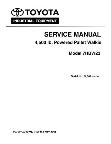
3.Remove any shields around the motor end cover to expose the brushes. See Figure6-39.
5.Remove the electromagnetic brake assembly by removing the three mounting bolts that secure the assembly to the motor end bell cover.
6.Remove the brake disc from the brake hub.
7.Remove the retaining ring that secures the brake hub. Remove the hub and woodruff key.
8.Remove the four screws and lock washers holding the brush end bell to the housing.
9.Separate the end bell from the motor housing. The armature will come out with the end bell.
10.To remove the end bell from the armature, remove the snap ring that holds the bearing in the end bell. If needed, press off the bearing and replace.
Installation
1.Thoroughly clean all parts with solvent or other non-corrosive cleaning fluid. Air dry all parts.
NOTE: Assemble the drive motor in a dirt-free area.
4.Lift the spring off the brush, pull the brush out of the holder.
5.Follow the brush replacement instructions. See “Drive Motor Brush Inspection” on page6-35.
6.Replace the shields around the motor end that were removed in step 3.
Motor Disassembly
1.Press the red OFF (O) key on the keypad. Disconnect the battery connector.
2.Remove the tractor covers.
3.Disconnect the power cables from the terminal block on the drive motor, noting their correct position.
4.Follow steps 1 through 5 in “Disassembly” on page6-28 to remove the top (pinion) gear attached to the motor armature shaft.
2.If previously removed, install the drive motor bearing, bearing shim, and seal in the gear case.
NOTE: The seal must be replaced any time the motor is removed from the housing. The seal must be installed correctly with its open side and seal ring positioned towards the bearing.
3.Reinstall the end bell cover, with the brush plate attached, on the motor armature shaft.
4.Carefully slide the drive motor armature in the motor housing.
5.Attach the end bell cover to the motor housing with the four cap screws.
6.Install the pinion gear, woodruff key, and the retaining ring on the armature shaft.
7.Use Permatex gasket eliminator on the mating surface and install the gear case cover.
8.Make sure the drive unit is filled to the correct level with gear oil. Install the fill/level plug. See “Drive Housing Lubrication” on page6-30.
9.Install the brake hub and woodruff key, and secure with the retaining ring.
10.Install the brake disc on the hub.
11.Install the brake coil assembly and attach with three hex head cap screws.
12.Reattach the power cables and electromagnetic brake wiring connections to the terminal block.
13.Before testing operation, move the handle from extreme left to right and down into operating position and back several times. Check for any wire and cable interference. Repair or adjust as necessary.
14.Install the battery, reconnect the battery connector and the turn the Master Control ON/OFF switch ON. Enter your PIN-key code then press the green ON (I) key on the keypad.
15.Test the operation of the truck.
Pallet Forks and Load Wheels
NOTE: For replacement parts information refer to Parts Catalog.

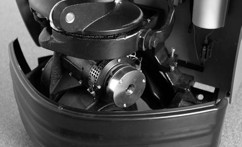
Load Wheels
Load wheels are installed on each pallet fork and are designed to support the rated load at the forks fully raised height.
Removal and Replacement
1.Lift the forks to maximum height and block them. See “Jacking Safety” on page2-9.
2.Remove the axle set screw. See Figure6-40.
Pallet Forks and Load Wheels
position with a plastic mallet. Make sure the bearing is fully seated in the load wheel.
8.Align the wheel with the holes in the load arm casting.
9.Drive the axle through the load arm casting and wheel. Align the “dimple” in the axle with the set screw hole.
10.Install and tighten the set screw.
Load Wheel Pull Rod
Load wheel pull rods are installed on each fork and are designed to transfer the hydraulic cylinder lifting action at the tractor end to the load wheel fork.
Removal and Replacement
NOTE: It may be easier to work with the truck upside down. Remove the battery before turning the truck over. Some oil may leak from the hydraulic reservoir.
1.Extend the load wheel forks. Remove the set screw and shaft connecting the wheel fork to the pallet fork. See Figure6-41.
3.Drive the axle out of the load arm casting with a hammer and brass drift pin.
4.Push the wheel out.
5.If the bearings are to be reused, insert a brass drift pin into each end of the load wheel and knock the bearings out.
6.Install the bearings in the new load wheel with the shields facing out.
7.Place the new load wheel upright on a flat surface. Position the bearing over the load wheel. Put a flat metal plate over the bearing, and hammer the bearing in
00700-CL340-05,
3.With the lower links out of the lift frame channels, the links can be separated and the pull rod removed from the link pin. Each link has one set screw at opposite
Pallet Forks and Load Wheels
ends. The link can be pulled apart without removing any other set screws.
4.Press new bushings in the pull rods, if necessary.
5.Reassemble the pull rods on the lower links and press the links together so they will fit in the frame channel.
6.Reinstall the pivot shaft and the retaining bolt in the lower links.
7.Reconnect the pull rod to the wheel fork.
8.Place the truck upright and install the battery. Connect the battery. Check the reservoir fluid level. Test the operation of the lift frame.
Carrier Frame Linkage
NOTE: For replacement parts information refer to Parts Catalog.
The bushings on the lower links can be replaced by removing the links from one side at a time and pressing in new bushings.

1.To separate the lift and carrier frames, remove all battery connections before removing the links.
2.Remove the upper and lower linkages and lift the lift frame off the carrier frame. See Figure6-42.
Hydraulic Components
General Guidelines
To prolong the life of your Toyota Pallet Truck, follow these guidelines:
•Keep all fittings and connections tight to prevent leaks. Do not over-tighten brass fittings or they may become damaged or distorted.
•Before you remove any component from the hydraulic system, wash the component and surrounding area with cleaning solvent to prevent foreign matter from entering the system. Cap and plug all openings immediately.
•Whenever you remove a fitting with a pipe thread, use a sealing compound on the outside of the threads before you reinstall the fitting. (Do not use Teflon® tape.) Make sure all parts are clean.
•When you install a hose assembly, make sure that it is not twisted when the fittings are tightened. Always use two wrenches on a swivel-type fitting—one to hold the fitting and the other to tighten the hose.
Hydraulic Cylinder
Fluid leakage indicates that the seal is worn. Replace the seal, wiper, and retaining ring when fluid leakage becomes excessive.
Cylinder Removal
1.Remove the tractor cover.
2.Remove retaining clip (see Figure6-43).
3.Press the green ON (I) key on the keypad. Leave the control handle in the neutral (vertical) position.
4.Press the lift button, raise the forks to maximum height and block them. See “Jacking Safety” on page2-9.

5.Lower the forks on the blocking to release pressure on the hydraulic cylinder. Manually press down on the cylinder after the forks come to rest on the blocking to disengage the cylinder from the tractor frame.
6.Press the red OFF (O) key on the keypad. Disconnect the battery connector.
Hot oil under pressure is present. Make sure truck is safely blocked and pressure is released.
7.Thoroughly clean the outside of the cylinder before removing the hydraulic hose. Remove the hose from the cylinder. Cap and plug the fittings.
NOTE: Catch hydraulic fluid under the hydraulic cylinder in a suitable container.
Hydraulic Components
8.Lift the cylinder up and out of the tractor frame. Some spillage of hydraulic oil may occur.
Cylinder Disassembly
1.Thoroughly clean the outside of the cylinder.
2.Pull the rod out until the end of the rod and the retaining ring are visible through the inlet port. See Figure6-45.
3.Insert a screwdriver into the inlet port and slide the retaining ring into the deep groove in the piston rod assembly.
4.Remove the rod assembly from the barrel.
5.Remove the retaining ring from the piston rod.
6.Remove the wiper and seal from inside the barrel assembly.
2.Install new seal in the barrel. Install new wiper in the barrel with lips facing inward.
3.Install new retaining ring in deep groove of the piston rod end.
4.Oil outside of piston rod and carefully insert rod into barrel.
5.Push rod into barrel until the retaining ring is seen through the inlet port.
6.Insert a screwdriver into the inlet port and slide the retaining ring into the lock position.
7.Extend rod to full out position to make sure the retaining ring is locked in place.
Cylinder Installation
1.Place the new cylinder into position in the tractor frame. Install retaining clip (see Figure6-43).
NOTE: To prevent air from filling the cylinder, install the cylinder with the rod retracted.
2.Connect the hydraulic hose.
3.Reconnect the battery connector and press the green ON (I) key on the keypad.
4.Press the lift button to extend the cylinder.
5.Check the hydraulic reservoir fluid level. If necessary, add fluid. See “Lubrication Equivalency Chart” on pageA-2.
6.Remove the blocking. Lift and lower the forks several times. Look for leakage around the fittings and cylinder seal.
Cylinder Inspection
1.Thoroughly clean all parts and remove all nicks and burrs with emery cloth.
2.Inspect the inside surface of the barrel assembly for excessive wear or scoring.
3.Inspect the outside surface of the rod for nicks, scratches, or scoring.
Cylinder Assembly
1.Make sure all parts are cleaned and dried thoroughly. Lightly oil all metal parts before reassembly.
7.Recheck the hydraulic reservoir fluid level. If necessary, add fluid.
8.Install the tractor cover.
Hydraulic Components
Hydraulic Solenoid
The hydraulic solenoid activates the hydraulic solenoid release valve that releases pressure on the lift cylinder, lowering the forks. See Figure6-46.
Removal
1.Make sure that the forks are fully lowered.
2.Press the red OFF (O) key on the keypad. Disconnect the battery connector.
3.Remove the two wires from the terminals on the solenoid.
4.Remove the nut holding the solenoid coil to the solenoid valve.
5.Lift the solenoid coil off the solenoid valve stem.
6.Remove the solenoid valve stem from the manifold.
Installation
1.Inspect the seat where the solenoid valve stem seals against the manifold. The sealing surface must be completely clean and free from any nicks or damage.
2.Thread the solenoid valve body into the manifold. Torque the valve body to 204 to 240 in. lbs (23 to 27 Nm).
3.Install the solenoid coil and tighten the nut. Torque the nut to 48 to 60 in. lbs (5 to 7 Nm).
4.Connect the wires to the terminals.
5.Reconnect the battery connector and press the green ON (I) key on the keypad. Test the functions of the truck.
6.Press the red OFF (O) key on the keypad. Disconnect the battery connector.
7.Install the tractor cover.
Hydraulic Unit
Draining and cleaning the hydraulic reservoir is important to control the accumulation of condensation and contamination that can damage the hydraulic system.

Condensation is caused by the repeated heating and cooling of hydraulic fluid during normal operation. Contaminants include dirt, rust, scaling and products of fluid deterioration.
Removal
Remove the hydraulic unit from the truck in order to separate the pump from the motor.
1.Lower the forks completely.
2.Press the red OFF (O) key on the keypad. Disconnect the battery connector. Remove the tractor cover.
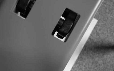
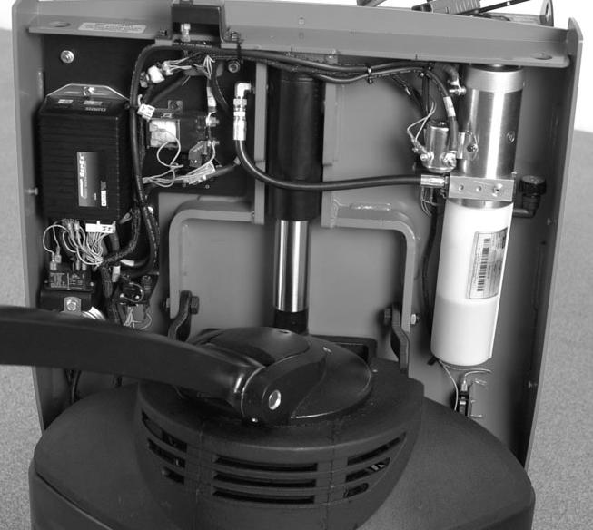
3.Remove and tag all wires and cables connected to the pump motor. See Figure6-47.
4.Remove and cap the hydraulic line from the hydraulic unit. Disconnect the solenoid control wires.
5.Remove the bolts that attach the hydraulic unit mounting bracket to the tractor frame.
6.Remove the hydraulic unit from the truck.
00700-CL340-05, Issued: 2 May 20056-49
Hydraulic Components
Installation
1.Install the hydraulic unit on the tractor frame and attach with the previously removed screws.
2.Install the hydraulic line on the hydraulic unit.
3.Fill the reservoir with the specified hydraulic fluid. See “Lubrication Equivalency Chart” on pageA-2. Use a funnel with a flexible neck. Fill the reservoir to within 1 in. (25.4 mm) below the filler plug elbow. Use up to 0.8qt. (0.75 liters). See Figure6-47.
4.Install the vent plug. See Figure6-47.
5.Connect all wires and cables to the pump motor switch and hydraulic solenoid.
6.Connect the battery connector and press the green ON (I) key on the keypad.
7.Raise and lower the forks. Check all hoses and fittings for leaks.
8.Lower the forks.
9.Check the hydraulic fluid level in the reservoir.
Hydraulic Reservoir Removal
1.Remove the hydraulic unit from the truck. See “Removal” on page6-49.
2.Remove the hose clamp that secures the hydraulic reservoir to the adapter housing.
3.Tap the reservoir lightly to loosen. Wiggle the reservoir sideways while pulling up on the pump and motor at the same time to remove.
4.Remove the reservoir and properly dispose of the old hydraulic fluid.
5.After the fluid has drained, flush the inside of the reservoir with a suitable cleaning solvent.
6.Dry the inside of the reservoir with clean, dry compressed air.
Installation
1.Inspect the reservoir O-ring and the inside leading edge for damage. Replace if necessary.
2.Lubricate the O-ring (with applicable hydraulic fluid) and install the O-ring.
3.Carefully install the reservoir on the adapter housing and attach with hose clamp. Torque clamp to 48 to 60 in. lb. (5.5 to 7 Nm).
4.Install hydraulic unit in the truck. See “Installation” on page6-50.

Filter Screen and Inlet Tube
1.Remove the reservoir. See “Hydraulic Reservoir”.
2.With the pump assembly inverted, unthread and remove the inlet tube fitting and sealing washer from the pump housing.
3.Clean the filter screen at the bottom of the inlet tube with a suitable solvent. See Figure6-48.
4.From the pump side, blow dry with clean, dry compressed air.
Installation
1.Inspect the filter screen and inlet tube for damage. Replace if necessary.
2.Install the inlet tube sealing washer and fitting in the pump housing. Torque to 245 to 275 in. lbs. (27 to 31 Nm).
3.Install the hydraulic reservoir. See “Hydraulic Reservoir”.
Hydraulic Pump
NOTE: For replacement parts information refer to Parts Manual.
Removal
1.Remove the hydraulic unit from the truck and put on a clean bench for disassembly. See “Hydraulic Unit” on page6-49.
2.Remove the reservoir to gain access to the pump. See “Hydraulic Reservoir”.
3.Remove the inlet tube with the filter screen from the pump housing.
4.Remove the two pump mounting bolts then remove the pump from the adapter body.
Installation
1.Stand the motor assembly on end, with the adapter body facing up.
2.Lubricate the O-ring and install on the adapter body facing up.

3.Insert the pump drive coupling on the end of the motor armature shaft, and fill the cavity with lubricant (Molybdenum anti-seize compound).
4.Align the splines on the motor drive and pump shaft. Gently push the pump pilot on the adapter.
5.Secure the pump with the two pump mounting bolts. Torque to 40 to 45in.lb. (4.5 to 5 Nm).
6.Check the inlet screen for clogging. Clean with a suitable solvent. Install the inlet tube fitting into the pump. Torque fitting to 245 to 275 in. lb. (27 to 31 Nm).
7.Install the reservoir. See “Hydraulic Reservoir” on page6-50.
Lift Motor Removal
1.Remove the hydraulic unit from the truck. See “Hydraulic Unit” on page6-49.
2.Remove the two bolts from the end plate that attach the motor to the adapter body.
3.Separate the motor and the adapter body.
4.Remove the start solenoid from the side of the motor housing for later reuse.
Hydraulic Components
Installation
1.Stand the pump assembly on end, with the adapter body facing up.
2.Set aside the pump drive coupling for later reuse.
NOTE: The coupling is the mechanical connection between the pump shaft and the electric motor armature shaft. It may have been removed with the motor.
3.Insert the pump drive coupling on the end of the pump shaft and fill coupling cavity with lubricant (Molybdenum anti-seize compound).
4.Rotate the pump or the motor shaft to align the motor shaft correctly with the coupling.
5.Install the new motor on the adapter body. Rotate the pump or the motor shaft if necessary to allow the motor to contact the adapter body.
6.Insert the screws into the motor end plate, through the motor, and into the adapter body.
7.Make sure the motor is mating flush with the adapter body. Torque screws to 36 to 45 in. lb. (4 to 5 Nm) maximum.
8.Install the start solenoid.
9.Install the hydraulic unit. See “Hydraulic Unit” on page6-49.

Brush Replacement
Brush Replacement Replace brushes when they have worn to the minimum length of 0.35 in. (9 mm).
Spring Tension Adjust the spring tension of new brushes to 32 to 40 oz. (908.8 to 1136gm).
1.Remove the lift motor from the hydraulic assembly before inspecting brushes.
2.Remove the two screws from the motor end cover. Remove end cover to access brushes.
3.Push each brush back into holder to disengage springs. Remove nuts and washers from side of drive end head.
Remove brush assembly then remove each brush and replace with a new one.
Hydraulic Fluid
Proper Level
To prevent air from entering the lines, fill the fluid level (with the forks fully lowered) to within 1 in. (25.4 mm) below the fill port elbow. See Figure6-44. The usable reservoir capacity is 0.8 qt. (0.75 L). Add the specified fluid if necessary. See “Lubrication Equivalency Chart” on pageA-2.
Changing Fluid
Store and handle the hydraulic fluid with extreme care to prevent moisture and foreign matter from entering the hydraulic system.
Contaminated hydraulic fluid is the major cause of hydraulic system failures. Keep any service equipment, such as containers, funnels, and hand pumps, clean at all times. Cover them when not in use.
1.Lower the forks.
2.Press the red OFF (O) key on the keypad. Disconnect the battery connector.
3.Remove the upper tractor cover.
4.Disconnect the lift cylinder hose at the hydraulic cylinder. See Figure6-49.
5.Insert the hose in a waste fluid container. Fluid is under pressure and may spray or splash. Point hose away from your body and hold firmly in waste fluid container.
6.Connect the battery connector and press the green ON (I) key on the keypad.
7.Run the hydraulic pump by pressing the lift button until all the hydraulic fluid is pumped from the system.
8.Press the red OFF (O) key on the keypad. Disconnect the battery connector.
9.Reconnect the lift cylinder hose.
10.Remove the vent plug and fill the reservoir to within 1 in. (25.4 mm) below the filler port elbow with the recommended hydraulic fluid. See “Lubrication Equivalency Chart” on pageA-2.
11.Replace the vent plug.
12.Connect the battery connector and press the green ON (I) key on the keypad.
13.Raise and lower the forks several times to purge air from the system.
14.Install the upper tractor cover.
15.Dispose of the waste fluid properly.
Adjusting Hydraulic Pump Pressure Relief Valve
The hydraulic system is protected by a relief valve installed in the adapter body. The relief valve is set by the manufacturer to open at a specified pressure.
Relief Valve Settings
Check Setting
1.Attach a jumper wire across the terminals of the lift-limit switch so the switch will not shut the pump down when the forks reach their upper limit.
2.Retract the lift cylinder completely. Press the red OFF (O) key on the keypad. Remove the 90° elbow. Replace the elbow with a female run tee with a 1/8 in. NPT 0to 3,500 psi (0 to 24131 kPa) pressure gauge. See Figure6-50.
3.Press the green ON (I) key on the keypad. Leave the control handle in the neutral (vertical) position.
4.Press the lift button and observe the indicator on the pressure gauge. When the forks reach the upper lift-limit, the pump will make a high pitched squeal indicating that the relief valve is opening.
Adjust Setting
If the relief valve opens at a lower or higher pressure than the specified pressure, adjust the relief valve as follows:
1.Remove the hex cap covering the relief valve adjustment screw.
2.As you depress the lift button, turn the adjusting screw inward to increase the
Hydraulic Components
pressure setting or outward to decrease the pressure setting.
3.Check the indicator on the pressure gauge. After the relief valve is properly set, release the lift button.
4.Reinstall the hex cap. Torque to 144 to 180in. lb. (16 to 20 Nm).
5.Recheck the relief valve setting.
6.Lower the forks completely. Press the red OFF (O) key on the keypad.
7.Remove the pressure gauge. Replace the elbow.
8.Press the green ON (I) key on the keypad. Raise the forks. Inspect all hoses and fittings for leaks.
9.Adjust the lift-limit switch to shut down the pump when the forks reach their upper limit. See “Lift-Limit Switch” on page6-25.
Cold Storage Conditioning
New Toyota Pallet Trucks supplied with a standard conditioning package are designed to operate in an environment where temperatures range from 32° to 104°F (0°to 40°C) in a continuous duty cycle.
Trucks supplied with a cold storage conditioning package are designed to operate in temperatures to 5°F (–15°C) in a continuous duty cycle or to –13°F (–25°C) for in and out operation.
When a truck is installed in a cold storage environment, change the fluid in the hydraulic reservoir according to the recommended fluids listed in the Appendix. See “Lubrication Equivalency Chart” on pageA-2.
00700-CL340-05,
00700-CL340-05, Issued: 2 May 2005A-1