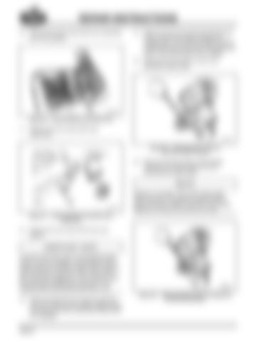
REPAIR INSTRUCTIONS 10. Remove the main case shift cover assembly and cover gasket. 66
14. Reach into the main case top opening and move at least two sliding clutches into engagement. This locks two different gears to the mainshaft and prevents the gears and shaft of the transmission from rotating. 15. Remove the drive yoke nut from the extended output shaft. 68
Figure 66 — Removing Main Case Shift Cover
11. Remove the rear case shift cover capscrews. 67
Figure 68 — Removing Drive Yoke Nut (T313L21/T318L21 Shown)
16. Remove the drive yoke or drive flange capscrew and clamp plate from the conventional output shaft.
Effective June 2007, drive yoke clamp plate capscrews were changed to a Scotch-Grip™ torque retention method. DO NOT reuse these fasteners, as they are one-time use only. Figure 67 — Removing Rear Case Shift Cover Capscrews
69
12. Remove the rear case shift cover and gasket.
To remove the drive yoke nut (extended output shaft) or yoke (or flange), clamp plate bolt and clamp plate (conventional output shaft), place at least two gears in both the main case and the rear case into engagement. This is done to lock the transmission gearing and prevent it from rotating while removing the yoke bolt or nut. 13. Reach through the rear case top opening and verify that both the splitter sliding clutch and the synchronizer assembly sliding clutch are engaged. Page 52
Figure 69 — Removing Clamp Plate and Capscrew (T313L/T318L Shown)
