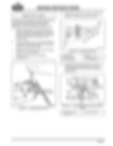
REPAIR INSTRUCTIONS 91. Install the interlock O-ring, pin, spring and sleeve into the main case shift cover. 578
On the very rare occasion of clutch tooth contact, the noncurrent eccentric pivot pin, which is available for service should be installed. Adjustment of the eccentric pivot is as follows: a.
Loosen the locknut on the eccentric pin. While rotating the transmission input shaft by hand, adjust the eccentric pin until gear clash occurs. Note the position of the eccentric pin.
b.
Turn the eccentric pin in the other direction until gear clash occurs again and note the position of the eccentric pin.
c.
Return the eccentric pin to a point midway between the two positions.
d.
Tighten the locknut to 54–68 N•m (40–50 lb-ft).
Figure 578 — Range Shift Interlock 1. Interlock Pin 2. Interlock Spring 3. Interlock Sleeve
4. O-Ring 5. Main Case Shift Cover (For Reference)
577
92. Position the range shift valve over the tip of the interlock pin. Install the two (outer) Allen-head 5/32-inch screws and torque to specification. 579
Figure 577 — Adjusting Eccentric Pin
Figure 579 — Tightening Range Shift Interlock Valve Screws 1. Allen-Head Screws (5/32 inch)
2. Range Shift Valve
Page 221
