REPAIR INSTRUCTIONS 1. Install the synchronizer pins into one of the two identical synchronizer clutch housings. Install the pins with the marked letter “R” facing up. Alternate pin heads as shown in the following figure.
2. The three synchronizer preload springs are made up of two pieces. Make sure that the preload springs are assembled with smooth-sided inner portion of the spring, inside the notched (detent) outer portion of the spring. 361
As you install the pins, notice that the pins and the sliding clutch are marked with the letter “R,” which stands for “Rear.” All the R marks on either end of the pins are placed on the same side of the sliding clutch marked with the letter R. During reassembly, make sure to coordinate all R marks on both the pins and sliding clutch of the synchronizer assembly. All R marks must face the rear of the transmission when installed. 359
Figure 361 — Assembling Preload Springs
3. Position the synchronizer sliding clutch on the bench with the marked letter “R” facing up. Install the three preload springs into the sliding clutch holes provided. The smaller holes are ramped and found halfway between the three largest holes. 362
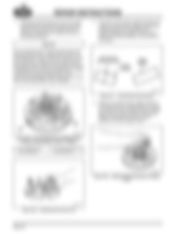
Figure 359 — Synchronizer Pins and Sliding Clutch Temporarily Assembled to Show “R” Marks 1. “R” on Sliding Clutch, Faces Rearward
2. “R” on Synchronizer Pins, Faces Rearward
360
Figure 362 — Installing Preload Springs into Sliding Clutch
Figure 360 — Installing Synchronizer Pins
Page 148
