RT9150E OPERATOR MANUAL
OPERATING CONTROLS AND PROCEDURES
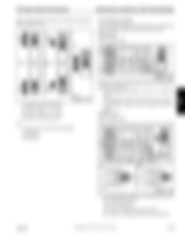
Near a locking point, the display (3) indicates the following, refer to (Figure 3-163):
Lock Telescope Cylinder The telescope cylinder must be locked to a telescopic section so that the telescopic section can be moved.
Prerequisites Refer to Figure 3-164.
FIGURE 3-164 In order to lock the telescope cylinder the following conditions must be met:
FIGURE 3-163 •
The distance to the locking point;
•
The telescoping mechanism must be on, symbol (3) green
•
The telescopic section must be locked, symbol (2) grey
•
The telescope cylinder must be unlocked, symbol (1) yellow.
(A) Yellow: Approx. 1 m (3.3 ft) (B) Yellow: Less than 1 m (3.3 ft)
To Select Lock
(C) Green: At the locking point
Refer to Figure 3-165.
and •
The direction of travel to the locking point; (1) Extending (2) Retracting
FIGURE 3-165 1.
Move the telescope cylinder to the desired locking point, e.g. to telescopic section 3. Wait until the display (2): (A): shows the desired telescopic section or, (B): shows no telescopic section and the desired
Grove
Published 2-18-2016, Control # 614-00
3-143
3


