68 minute read
RT9150E OPERATOR MANUALOPERATING CONTROLS AND PROCEDURES


(6) Locked left
(7) Unlocked left
(8) Unlocked right
(9) Locked right
For fault-free proximity switches, the following applies: Green: Position reached Red: Position not reached
Required Inspection
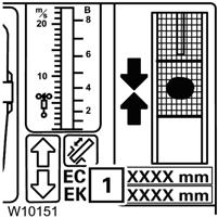
Refer to Figure3-186.
When the locked position can no longer be displayed, always conduct the following check before unlocking:
1. Carefully retract and extend the telescoping cylinder or telescopic section.
2. In the locked position, the length shown on the displays (1) should vary only slightly, i.e. by the play of the locking pins.
Retracting
Refer to Figure3-187.
Caution
Equipment Damage Hazard!
Extend the telescope cylinder (without telescopic section) only to the specified length.
This prevents the piston rod from becoming damaged if the telescope cylinder slides out of the telescopic section.
The steps for retracting are the same when an error occurs on the proximity switch as for an error on the length indicator.
When the display (C) fails:
1. Calculate the telescope cylinder length for the locking point;
- Refer to Locking Points for the Telescoping Cylinder, page 3-153,
- Refer to Locking Points for the Telescopic Sections, page 3-153.
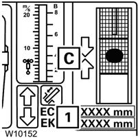
2. Move the telescoping cylinder to the required length shown in display (1).
Terminating the Emergency Program
The emergency program is terminated:
- If the displayed time has expired or
- when the ignition is turned off.
NOTE: The current telescoping status does not correspond to the telescoping status last saved by ECOS if the Telescope Emergency Program was open. You must enter the current telescope status after terminating the emergency program, refer to Entering the Current Telescope Status, page 3-60.
Tables for Approaching the Locking Points
The extent to which the telescope cylinder has to be extended in order to reach a locking point depends on whether you:
- Want to lock the telescope cylinder or - lock a telescopic section.
Locking Points for the Telescoping Cylinder
The following table shows the extended length for locking the telescoping cylinder.
Table for locking the telescoping cylinder
Locking Points for the Telescopic Sections
Refer to Figure3-188.
The locking pin must not engage the telescopic section for locking or unlocking it.
The notch (1) must be clear. That is why you have to extend the telescoping cylinder 0.38 in (35 mm) further than with a return run.
The following table shows the extended length for locking and unlocking the telescopic sections.
Table for locking/unlocking the telescopic sections
Hoist Operation
Refer to Main Menu, page 3-21 for information on using the ECOS system.
Lowering and Raising the Hoist Cable
Danger
Crushing Hazard!
Keep the area beneath the load clear of all obstructions and personnel when lowering or raising the cable (load). Death or serious injury could result if the load should fall.
Caution
Machine Damage Hazard!
Do not jerk the control lever when starting or stopping the hoist. Jerking the lever causes the load to bounce, which could result in possible damage to the crane.
NOTE: When the load is stopped at the desired height, the automatic brake will engage and hold the load as long as the control lever remains in neutral.
Main Hoist
To lower or raise the main hoist cable, use the controls on the right-hand armrest:
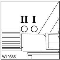
3. On the RCL Monitoring submenu, check whether lamp I is on.
If lamp I is flashing, turn off both hoists and turn on hoist I again to switch the display to lamp I , refer to Verify Hoists Display, page 3-123.
4. Check that the actual reeving of the main hoist (1) is displayed correctly. Correct the reeving if necessary, refer to Verify Reeving, page 3-124.
5. Using the right-hand joystick controller:
- Push forward and hold until the hook or load is lowered to the desired height,
- Pull backward and hold until the hook or load is raised to the desired height.
6. Push the top of the Main Hoist switch again to turn off the function.
Auxiliary Hoist
To lower or raise the auxiliary hoist cable, use the controls on the left-hand armrest:
Published 2-18-2016, Control # 614-00 Grove
3. On the RCL Monitoring submenu, check whether lamp II is on.
If lamp II is flashing, switch the display to lamp II , refer to Verify Hoists Display, page 3123.
4. Check that the actual reeving of the auxiliary hoist (1) is displayed correctly. Correct the reeving if necessary, refer to Verify Reeving, page 3-124.
5. Using the left-hand joystick controller:
- Push forward and hold until the hook or load is lowered to the desired height,
- Pull backward and hold until the hook or load is raised to the desired height.
6. Push the top of the Auxiliary Hoist switch again to turn off the function.
Hoist Speed Range Selection
Caution
Do not change the hoist speed range with the hoist rotating.
To change the speed range of the hoist, use the switch on top of the appropriate joystick controller.
Push and hold the switch to the left for momentary high speed operation, release for normal speed.
Push the switch to the right to turn high speed on or off, for continuous high speed operation.
Boom Extensions
When operating the crane with a boom extension installed, the maximum speed for the different power units is limited to 70%.
WARNING!
Equipment Damage Hazard!
During operation with the 36ft (11m) boom extension set at 0° angle at the steepest boom position, the head sheaves of the main boom can be damaged when a hook block is raised or lowered. Reduce the hoist speed so that the hook block is raised slowly passed the head sheaves.
Setting the RCL
When a boom extension is installed the associated displays change to include its graphical representation.
NOTE: If a hook block is reeved on the main boom during operation with a boom extension, the loads given in the Load Chart decrease and the RCL subsequently switches off earlier.
The values which must be deducted from the load capacities depend on the length of the boom extension and the weight of the hook block. You will find a table with the values in the Load Chart in the section; Information on working with the swingaway boom extension
Enter the following into the RCL when a luffing boom extension is installed, refer to Entering the Rigging Mode, page 3-81:
• hydraulic jib’s length
• mechanical jib’s length and the angle the jib is set at
• the actual rigging configuration;
- using the corresponding RCL code according to the Load Chart or
- using the individual components
• the current reeving.
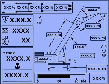
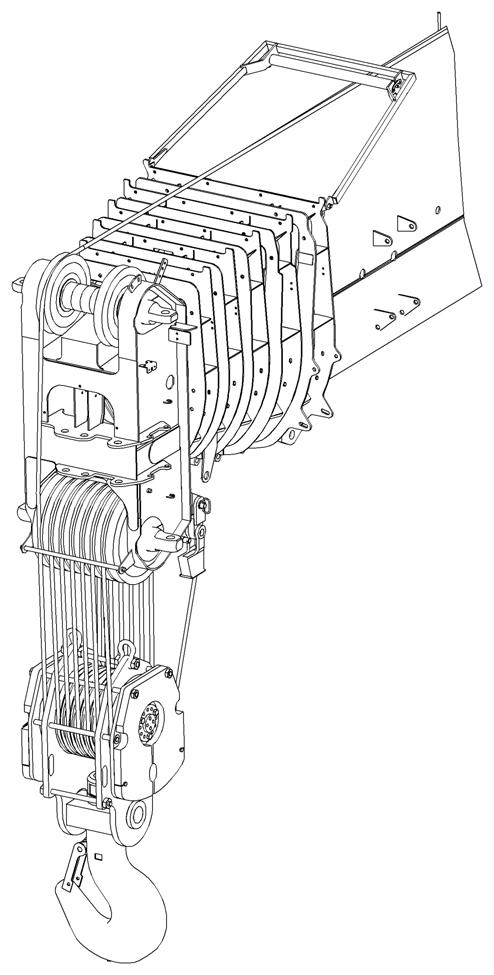
After entering the above information into the RCL, check that the following displayed values correspond with the actual rigging configuration of the crane (Figure3-189) in the Monitoring submenu, RCL Monitoring Submenu, page 3-86:
• (1) the number of reeved rope lines
• (2) the length of the rigged boom extension
• (3) with a mechanical luffing jib, the rigged angle
• (4) the length of the jib
• (5) the hoist that is switched on.
• (6) the rigged counterweight
• (7) the rigged outrigger span
• (8) the maximum load weight
• (9) the actual load weight
Load Bearing Capacities
When the telescopic sections are telescoped to a fixed length during operation with a luffing jib, the RCL changes the current value as determined by the Load Chart and displays the maximum load value (8) (Figure3-189).
Depending on the current angle, the RCL automatically switches to the Load Chart for fixed angles (0° inclination) and intermediate angles (0 - 20° or 20 - 40° inclination) when this is permitted for the load currently being raised.
Raising and Lowering the Hydraulic Boom Extension
The normal operating range for the hydraulic luffing boom extension (hydraulic luffing jib) is an offset of 0 - 40 degrees. The extension must be retracted to 0 degree offset for stowage on the side of the boom.
The hydraulic luffing boom extension is controlled by an ON/ OFF switch and joystick controller on the right-hand armrest.
Refer to Right-Hand Armrest Controls, page 3-11 for location and description of these switches.
The boom extension may also be controlled by the remote station on the extension. The station is located on the boom extension to the front of the luffing hydraulic cylinder, see (Figure3-190).
CAUTION!
Equipment Damage!
When lowering the boom extension, simultaneously let out the hoist cable to prevent two-blocking the extension sheave and the hookblock or headache ball.
Hydraulic Boom Extension Operation — Cab
In order to enable the operation of the hydraulic luffing jib the RCL code must be set for the current rigging mode, refer to Rigging Mode Submenu, page 3-78.
To lower or raise the hydraulic luffing jib, use the controls on the right-hand armrest:
1. Push the top of the Luffing Jib switch once.
2. ECOS indicator must be green.
3. Using the right-hand joystick controller:
-To lower the jib: push the controller to the right,
-To raise the jib: push the controller to the left.
4. Push the top of the Luffing Jib switch again to turn off the function.
To limit the speed to lower or raise the luffing jib refer to Power Unit Speed Submenu, page 3-48.
Hydraulic Boom Extension Operation — Remote Station
When using the remote station (Figure3-190) to operate the hydraulic luffing jib, press the button until the desired angle is reached or until the end position or a switch-off point is reached.
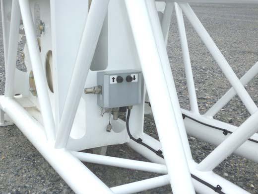
To lower or raise the hydraulic luffing jib, using the remote station:
-To lower the jib: push the right button,
-To raise the jib: push the left button.
Two Hook-Operation
Two-hook operation is permissible only when one of the following is installed:
- Swingaway boom extension
- Auxiliary single-sheave boom nose
- Heavy load boom extension.
For two-hook operation, both hoists must be activated on the RCL.
NOTE: Enter the reeving for both hoists before reeving the boom. The values are stored and opened directly when switching hoists. This eliminates the need for input later during operation.
1. Switch off both hoists by pressing each hoist switch once.
2. The ECOS indicators must turn red.
Main Hoist Right-hand Controls
Aux. Hoist Left-hand Controls
Main HoistAuxiliary Hoist
3. Switch on the main hoist by pressing its switch on the right-hand controls. The ECOS indicator turns green and the main hoist lamp I lights.
4. In the reeving display, enter the quantity of reeved ropes of the main hoist on the main boom.
5. Switch off the main hoist by pressing the switch once.
The ECOS indicator will turn red.
Now the reeving for the main hoist has been stored and you can switch to the auxiliary hoist.
6. Switch on the auxiliary hoist by pressing its switch on the left-hand controls.
The ECOS indicator turns green and the auxiliary hoist lamp II lights.
7. In the reeving display, enter the quantity of reeved ropes of the auxiliary hoist on the boom extension.
8. Switch on the main hoist by pressing its switch on the right-hand controls. The ECOS indicator turns green. The auxiliary hoist indicator II remains on and the main hoist indicator I flashes.
9. Enter RCL code according to the Load Chart for the actual rigging mode of the crane with the rigged boom extension.
The RCL is now set for two-hook operation. It now takes into account:
- The reeving for the auxiliary hoist
- The Load Chart for the boom extension.
Stowing and Parking
Warning
Tipping Hazard!
Never park the crane near holes, or on rocky or extremely soft surfaces. This may cause the crane to overturn.
Failure to comply with these instructions may cause death or serious injury.
When parking, the crane should be left in the smallest, most stable, valid operational configuration that the job site practically allows, do the following:
1. Park the crane on a stable surface.
2. Remove the load from the hook.
3. Stow the swingaway boom extension, if erected.
4. Fully retract the boom and position it in the normal travel position or at least as far as is practical to make the crane as stable as possible, including, boom angle, superstructure orientation, jib angle, etc. In high winds the boom and jibs should be lowered or secured.
5. Engage the swing brake and/or swing lock pin.
6. Retract all jack cylinders and outrigger beams.
7. Apply the parking brake.
8. Put all operating controls in the neutral position.
9. Actuate the Crane Function switch.
10. Shut down the engine following the proper procedures specified in this manual and the applicable engine manual.
11. Remove the keys.
Caution
To avoid possible engine fault codes and undesirable operation, ensure the keyswitch has been off 2 minutes before disconnecting batteries.
12. Disconnect batteries, if machine will be inactive for over 24 hours.
13. Close and lock all windows, covers, and doors.
Unattended Crane
Danger
Tipping Hazard!
Changing weather conditions including but not limited to: wind, ice accumulation, precipitation, flooding, lightning, etc. should be considered when determining the location and configuration of a crane when it is to be left unattended.
Failure to comply with these instructions may cause death or serious injury.
The configuration in which the crane should be left while unattended shall be determined by a qualified, designated individual familiar with the job site, configuration, conditions, and limitations.
Section 4
General
This section provides procedures for installing the hoist cable (wire rope) on the hoist drum, cable reeving, dead-end rigging, counterweight removal and installation, outrigger removal and installation, swingaway boom removal and installation, and hydraulic boom extension connecting and disconnecting.
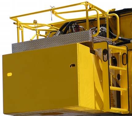
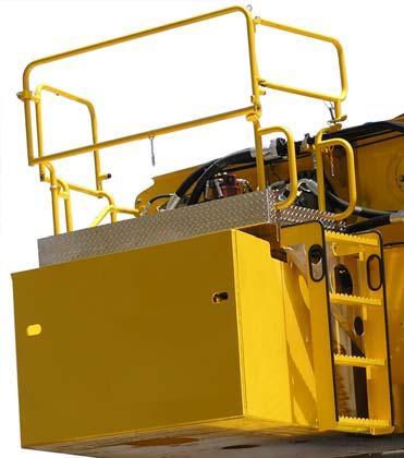
Accessing The Hoist Area
Change the hoist access area from the Travel Configuration (Figure4-1) to the Working Configuration (Figure4-2).
Warning
Platform must not be used for hauling passengers as death or serious injury could occur. No storage of components are allowed on the platform. Only one person at a time is allowed on the platform.
Travel Configuration
1. Front and rear railings are in the pinned and down position (1 pin installed, 1 pin stowed).
2. Rear post is in the down position (1 pin stowed).
3. Gate is in the open and down position (1 pin stowed).
Working Configuration
1. Front and rear railings are in the up position and pinned (2 pins installed).
2. Rear post is in the up position and pinned (1 pin installed).
3. Gate is closed and pinned in the up position (1 pin installed.
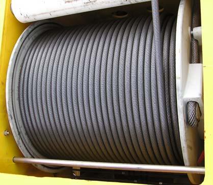
HOIST CABLE (WIRE ROPE)
NOTE: The cable should preferably be straightened before installation on the hoist drum.
Removing the Old Cable
Warning
Entanglement Hazard!
Keep all body parts and loose clothing clear while hoist is running. Death or serious injury may result if entanglement occurs during hoist operations.
NOTE: Make sure the crane is level and the main boom is fully lowered.
1. Unreel the hoist cable until the hoist switches off.
2. Adjust the lowering limit switch so that the cable can unreel completely.
3. Unreel remaining layers from the hoist drum.
4. Lock the cab to prevent unauthorized use.
Published 2-18-2016, Control # 614-00
5. Remove the clamp (1) (Figure4-3).
Caution
If cable is wound from the storage drum, the reel should be rotated in the same direction as the hoist. Damage to the wire rope may occur.
1. Tension the cable slightly while winding it onto the drum.
2. Place the reel stand (1) (Figure4-4) with the new cable in front of the main boom head.
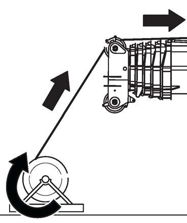
3. Guide cable over the head sheave (2) (Figure4-4) up to the hoist drum.
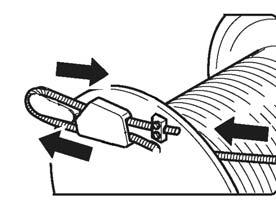
ItemDescription
1Clamp
2Pouch
3Cable Hole
4Cable Wedge
6. Push the cable through the hole (3) (Figure4-3) until the cable wedge (4) slides out of the pouch (2).
7. Remove the cable wedge and place the cable away from the crane.
Installing a New Cable
Warning
Entanglement Hazard!
Keep all body parts and loose clothing clear while hoist is running.
Death or serious injury may result if entanglement occurs during hoist operations.
4. Guide the cable through the hole (3) (Figure4-5) until it extends about 5.0 ft (1.5 m) beyond the pouch (2) (Figure4-5).
5. Feed the free end of the cable back through the pouch (2) (Figure4-5).
6. Secure the clamp (1) (Figure4-5) and tighten it. Torque to 58 lb-ft (79 Nm).
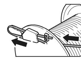
7. Place the cable wedge (4) (Figure4-5) in the loop.
Grove Published 2-18-2016, Control # 614-00
8. Push the cable back until cable wedge (4) (Figure4-6) is fully in the pouch (2) (Figure4-6).
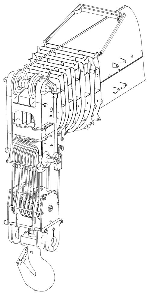
Cable Reeving
NOTE: There are two types of cable (wire rope) available on this crane; 6 x 36 WS and 35 x 7 (non-rotating). Within the limits of the load and range charts and permissible line pull, multi-part lines allow the operator to raise a greater load than can be raised with a single part line. Various cable reeving (part line) is possible with the boom nose and hook block (Figure4-12). This reeving should be accomplished by a qualified rigger using standard rigging procedures.
Caution
7592-9
FIGURE4-6
9. Ensure that the cable wedge (4) (Figure4-6) loop and cable end do not protrude beyond the flanged wheel. This will prevent damage.
10. Start the engine.
11. Hold the cable taut and wind up the cable slowly.
12. Reeve the hookblock at least 4 times.
13. Raise the main boom to a steep position and extend it fully.
14. Unwind the cable out until only five turns remain on the cable drum.
NOTE: Watch the hookblock when unwinding. The hookblock must not rotate.
Danger
Crushing Hazard!
After installing new cable, the lowering limit switch must always be reset. This will avoid the lowering limit switch from switching off too late or not at all, the cable being damaged and the load falling.
Death or serious injury may result from an improperly set limit switch.
15. Run in the new cable with small loads so that the hoist cable can settle on the drum.
Do not reeve Auxiliary Hoist cable through the cable grab. Reeve the Main Hoist cable through the cable grab. If both Main & Auxiliary Hoists are being reeved, neither one may be reeved through the cable grab. Keep it in the down position (Figure4-7).
NOTE: Use the cable grab (Figure4-7) when using the main hoist with lattice extensions.
In order to quick reeve the hook block without removing the wedge socket on the end of the cable refer to (Figure4-8).
DEAD-END RIGGING/WEDGE SOCKETS
Wedge socket assemblies are popular rigging accessories and have been successfully used for decades to terminate cables on mobile cranes. A wedge socket assembly is easily installed and dismantled but it must be installed and used correctly. It is essential to use only a wedge and socket of the correct size for the cable fitted. Failure to do so may result in the cable pulling through the fitting.
Since state and local laws may vary, alternate attachment methods may be necessary depending upon work conditions. If alternate methods are selected, the user is responsible and should proceed in compliance with the regulations in force. If there are any questions, contact your local Manitowoc distributor or Manitowoc Crane Care.
Do not mix components from different manufacturers. The selection, installation and use of a wedge socket assembly must be in accordance with the requirements of the wedge socket manufacturer and the cable manufacturer upon whose cable the wedge socket assembly will be used.
Manitowoc specifies the size, type, class and line pulls for cable, predominately rotation resistant cable, and rigging accessories such as overhaul balls and hook blocks for use with each new crane that it manufactures. Other cables and rigging accessories are available from various vendors. Different wire rope manufacturers have differing requirements for the construction, handling, cutting, seizing, installation, termination, inspection and replacement of the cables they produce. Their advice should be sought for each specific type of cable a crane user intends to install on a mobile crane.
When assembly is complete, raise the boom to a working position with a load suspended to firmly seat the wedge and cable into the socket before the crane is used operationally.
CAUTION!
If the socket is not positioned with the flat face away from the boom sections, structural damage will occur.
When anchoring the socket to the boom, ensure the flat face of the socket is in position, as shown, away from the boom sections (Figure4-9).
Installing Wedge and Socket
1. Inspect the wedge and socket. Remove any rough edges and burrs.
2. The end of the cable should be seized using soft, or annealed wire or strand. If the end of the cable is welded, the welded end should be cut off. Refer to Section 1, Wire Rope (Hoist Cable) for wire rope (cable) procedures. This will allow the distortion of the wire rope strands, caused by the bend around the wedge, to adjust themselves at the end of the line.
3. Make sure the live-loaded side (Figure4-10) of the wire rope is directly in line with the ears of the socket and the direction of pull to which the wire rope will be subjected. If the wire rope is loaded into the socket incorrectly, under a load the wire rope will bend as it leaves the socket, and the edge of the socket will wear into the wire rope causing damage to the wire rope and eventual failure.
4. Insert the end of a wire rope into the socket, form a loop in the wire rope, and route the wire rope back through the socket allowing the “dead” end (Figure4-10) to protrude from the socket. Ensure the dead end of the wire rope is of sufficient length to apply end treatment to the dead end after the wedge has been seated.
5. Insert the wedge into the loop and pull the live end of the wire rope until the wedge and wire rope are snug inside the socket. It is recommended that the wedge be seated inside the socket to properly secure the wire rope by using the crane’s hoist to first apply a light load to the live line.
6. After final pin connections are made, increase the loads gradually until the wedge is properly seated.
7. The wire rope and wedge must be properly secured inside the socket before placing the crane into lifting service. It is the wedge that secures the wire rope inside the socket whereas the dead-end treatment is used to restrain the wedge from becoming dislodged from the socket should the wire rope suddenly become unloaded from the headache ball or hook block striking the ground, etc.
Sketches A through F (Figure4-11) illustrate various methods for treating the dead-ends of wire ropes which exit a wedge socket assembly. While use of the loop-back method is acceptable, care must be exercised to avoid the loop becoming entangled with tree branches and other components during crane transport and with the anti-twoblock system and other components during use of the crane. Of the methods shown below, Manitowoc prefers that method A or F be used on Grove cranes, i.e., clipping a short piece of wire rope to the dead-end or using a commercially available specialty wedge. Typically, it is recommended that the tail length of the dead-end should be a minimum of 6 wire rope diameters but not less that 6 in (15.2 cm) for standard 6 to 8 strand wire ropes and 20 wire rope diameters but not less than 6 in (15.2 cm) for rotation resistant wire ropes.
When using method A, place a wire rope clip around the dead end by clamping a short extra piece of wire rope to the wire rope dead end. DO NOT CLAMP THE LIVE END. The U-bolt should bear against the dead end. The saddle of the clip should bear against the short extra piece. Torque the Ubolts according to the figures listed in the chart titled Wire Rope Clip Torque Values.
NOTE: Use of swivels is not allowed in conjunction with non-rotation resistant wire ropes
Other sources for information with which crane users should be familiar and follow is provided by the American Society of Mechanical Engineers, American National Standard, ASME B30.5, latest revised. ASME (formerly ANSI) B30.5 applies to cableways, cranes, derricks, hoists, hooks, jacks, and slings. It states, in section 5-1.7.3, “(c) Swaged, compressed, or wedge socket fittings shall be applied as recommended by the wire rope, crane or fitting manufacturer.” Wire ropes are addressed in ASME B30.5, section 5-1.7.2, ROPES, It states, in pertinent part, “(a) The wire ropes shall be of a construction recommended by the wire rope or crane manufacturer, or person qualified for that service.” Additional information is published by the Wire Rope Technical Board in the Wire Rope Users Manual, latest revised.
Fold-Up Deflection Sheave
Fold-Up Deflection Sheave
Fold-Up Deflection Sheave
Fold-Up Deflection Sheave
Fold-Up Deflection Sheave
Counterweight Removal And Installation
Counterweight Stand Installation
NOTE: The counterweight stands must be installed on the front of the carrier before installing or removing the counterweight.
1. Using an adequate lifting device, install the counterweight stands (1) (Figure4-13) to the front of the carrier frame (2) and secure with the hitch pins (3).
Standard Fabricated Counterweight Installation
Danger
Read and understand the following when removing and installing the counterweight or counterweight stand, to avoid serious injury or death.
•Outriggers must be fully extended and set and crane level before installation or removal of counterweight.
•Lifting operations are not permitted with any counterweight on the carrier deck except for the removal or installation of the counterweight.
•Boom is not permitted over carrier deck when the boom angle is less than 30° and any counterweight is positioned on deck.
•Hookblock is not permitted to come in contact with counterweight during removal or installation.
•Travel is not permitted with any counterweight on carrier deck.
1. Rig the crane with three parts of line.
2. The standard 39,000 lb (17,690 kg) fabricated counterweight may be lifted in one of the following boom configurations.
Danger
Crushing Hazard!
Adjustment of the counterweight stand supports is prohibited when the counterweight is resting on them.
The main boom must not be lowered below horizontal when swinging over the front while the counterweight supports are installed.
Death or serious injury may occur.
3. Enter RCL code 1100. Refer to RCL Main Menu, page 375.
4. Connect sling assembly to the standard counterweight using the installation lifting holes (Figure4-14).
5. Lift and place the counterweight onto the carrier stands.
6. Swing turntable to place the boom over the rear of the crane.
7. Set the turntable lock pin in the down position.
8. Using the ECOS display lower the counterweight cylinders into the tubes in the counterweight, refer to RCL Main Menu, page 3-75
9. Rotate the cylinders to lock into the counterweight.
10. Raise the counterweight until the display indicates the counterweight is pre-tensioned.
11. Using the ECOS display, extend the locking cylinders until the display indicates the counterweight is locked in place.
Standard Fabricated Counterweight Removal
1. Rig the crane with three parts of line.
2. The standard fabricated counterweight may be lifted in one of the following boom configurations.
Boom Configuration
3. Enter RCL code 1100. Refer to RCL Main Menu, page 375.
4.
5. Set the turntable lock pin in the down position.
6. Using the ECOS display, retract the locking cylinders until the display indicates the cylinders are fully retracted.
7. Lower the counterweight onto the carrier stands until the display indicates the counterweight is fully lowered.
8. Rotate the cylinders to unlock from the counterweight.
9. Using the ECOS display raise the counterweight cylinders from the tubes in the counterweight.
10. Swing the turntable to place the boom over-the-front.
11. Connect sling assembly to the standard counterweight using the installation lifting holes (Figure4-14).
12. Lift and place the counterweight onto the ground.
Grove Published 2-18-2016, Control # 614-00
Heavy Fabricated Counterweight Installation
Danger
Read and understand the following when removing and installing the counterweight or counterweight stand, to avoid serious injury or death.
•Outriggers must be fully extended and set and crane level before installation or removal of counterweight.
•Lifting operations are not permitted with any counterweight on the carrier deck except for the removal or installation of the counterweight.
•Boom is not permitted over carrier deck when the boom angle is less than 30° and any counterweight is positioned on deck.
•Hookblock is not permitted to come in contact with counterweight during removal or installation.
•Travel is not permitted with any counterweight on carrier deck.
Caution
Counterweight assembly must be completed on the ground; not on the carrier counterweight stand. Outrigger boxes must be installed and outrigger beams must be fully extended.
1. Rig the crane with five parts of line.
2. The heavy 63,000 lb (28,576 kg) fabricated counterweight may be lifted in one of the following boom configurations.
7. Lift and place the counterweight assembly onto the carrier stands.
8. Swing turntable to place the boom over the rear of the crane.
9. Set the turntable lock pin in the down position.
10. Using the ECOS display lower the counterweight cylinders into the tubes in the counterweight, refer to RCL Main Menu, page 3-75
11. Rotate the cylinders to lock into the counterweight.
12. Raise the counterweight until the display indicates the counterweight is pre-tensioned.
13. Using the ECOS display, extend the locking cylinders until the display indicates the counterweight is locked in place.
Heavy Fabricated Counterweight Removal
1. Rig the crane with five parts of line.
2. The 63,000 lb (28,576 kg) heavy fabricated counterweight may be lifted in one of the following boom configurations.
3. Enter RCL code 1100. Refer to RCL Main Menu, page 375.
4. Connect sling assembly to the 24,000 lb (10,886 kg) counterweight insert using the lifting eyes on the insert.
5. Lift and place the counterweight insert into the standard fabricated counterweight.
6. Connect sling assembly to the heavy fabricated counterweight assembly using the installation lifting holes (Figure4-14).
3. Enter RCL code 1100. Refer to RCL Main Menu, page 375.
4. Swing turntable to place the counterweight over the front of the crane.
5. Set the turntable lock pin in the down position.
6. Using the ECOS display, retract the locking cylinders until the display indicates the cylinders are fully retracted.
7. Lower the counterweight until the display indicates the counterweight is fully lowered onto the stands.
8. Rotate the cylinders to unlock from the counterweight.
9. Raise the counterweight cylinders from the tubes in the counterweight.
10. Connect sling assembly to the heavy counterweight assembly using the installation lifting holes.
11. Lift and remove the counterweight from the carrier stands.
12. Place the counterweight on the ground.
13. Disassemble the counterweight, if necessary.
17,690 kg (39,000 lb) Cast Counterweight
Installation
1. Rig the crane with three parts of line.
2. The 17,690 kg (39,000 lb) cast counterweight assembly may be lifted in one of the following boom configurations.
Danger
Read and understand the following when removing and installing the counterweight or counterweight stand, to avoid serious injury or death.
•Outriggers must be fully extended and set and crane level before installation or removal of counterweight.
•Lifting operations are not permitted with any counterweight on the carrier deck except for the removal or installation of the counterweight.
•Boom is not permitted over carrier deck when the boom angle is less than 30° and any counterweight is positioned on deck.
•Hookblock is not permitted to come in contact with counterweight during removal or installation.
•Travel is not permitted with any counterweight on carrier deck.
•Counterweight assembly must be completed on the ground not on the carrier counterweight stands.
3. Enter RCL code 1100. Refer to RCL Main Menu, page 375
4. Connect sling assemblies to the cast counterweight using the installation lifting holes (Figure4-15).
5. Lift and place the counterweight onto the support bracket (Figure4-15) on the ground.
6. Lift and place the counterweight/support bracket assembly onto carrier counterweight stands using the support bracket lifting eyes (Figure4-16).
16,705
Grove Published 2-18-2016, Control # 614-00
7. Swing turntable to place the boom over the rear of the crane.
8. Set the turntable lock pin in the down position.
9. Using the ECOS display lower the counterweight cylinders into the tubes in the counterweight/support bracket assembly, refer to RCL Main Menu, page 3-75
10. Rotate the cylinders to lock into the counterweight assembly.
11. Raise the counterweight until the display indicates the counterweight is pre-tensioned.
12. Using the ECOS display, extend the locking cylinders until the display indicates the counterweight is locked in place.
17,690 kg (39,000 lb) Cast Counterweight Removal
1. Rig the crane with three parts of line.
2. The 17,690 kg (39,000 lb) cast counterweight assembly may be lifted in one of the following boom configurations.
Boom
3. Enter RCL code 1100. Refer to RCL Main Menu, page 375
4. Swing turntable to place the boom over the rear of the crane.
5. Set the turntable lock pin in the down position.
6. Using the ECOS display, retract the locking cylinders until the display indicates the cylinders are fully retracted.
7. Lower the counterweight assembly onto the carrier stands until the display indicates the counterweight is fully lowered.
8. Rotate the cylinders to unlock from the counterweight.
9. Using the ECOS display raise the counterweight cylinders from the tubes in the counterweight.
10. Swing the turntable to place the boom over-the-front.
11. Connect sling assembly to the counterweight assembly using the support bracket lifting eyes (Figure4-16).
12. Lift and place the counterweight assembly onto the ground.
Heavy Cast Counterweight Installation
Danger
Read and understand the following when removing and installing the counterweight or counterweight stand, to avoid serious injury or death.
•Outriggers must be fully extended and set and crane level before installation or removal of counterweight.
•Lifting operations are not permitted with any counterweight on the carrier deck except for the removal or installation of the counterweight.
•Boom is not permitted over carrier deck when the boom angle is less than 30° and any counterweight is positioned on deck.
•Hookblock is not permitted to come in contact with counterweight during removal or installation.
•Travel is not permitted with any counterweight on carrier deck.
•Counterweight assembly must be completed on the ground; not on the carrier counterweight stands.
1. Rig the crane with five parts of line.
2. The heavy 63,000 lb (28,576 kg) cast counterweight assembly may be lifted in one of the following boom configurations.
3. Enter RCL code 1100. Refer to RCL Main Menu, page 375
4. Connect sling assemblies to the 16,705 kg (36,825 lb) cast counterweight using the installation lifting holes (Figure4-15).
5. Lift and place the counterweight onto the support bracket on the ground.
6. Connect sling assembly to the 10,902 kg (24,035 lb) cast counterweight insert using the lifting lugs on the insert (Figure4-17).
15. Using the ECOS display, extend the locking cylinders until the display indicates the counterweight is locked in place.
Heavy Cast Counterweight Removal
1. Rig the crane with five parts of line.
2. The heavy 63,000 lb (28,576 kg) cast counterweight assembly may be lifted in one of the following boom configurations.
7. Lift and place the counterweight insert into the 16,705 kg (36,825 lb) cast counterweight.
8. Connect sling assembly to the heavy cast counterweight assembly using the support bracket lifting eyes (Figure4-16).
9. Lift and place the counterweight assembly onto the carrier stands.
10. Swing turntable to place the boom over the rear of the crane.
11. Set the turntable lock pin in the down position.
12. Using the ECOS display lower the counterweight cylinders into the tubes in the counterweight, refer to RCL Main Menu, page 3-75
13. Rotate the cylinders to lock into the counterweight.
14. Raise the counterweight until the display indicates the counterweight is pre-tensioned.
3. Enter RCL code 1100. Refer to RCL Main Menu, page 375
4. Swing turntable to place the counterweight over the front of the crane.
5. Set the turntable lock pin in the down position.
6. Using the ECOS display, retract the locking cylinders until the display indicates the cylinders are fully retracted.
7. Lower the counterweight until the display indicates the counterweight is fully lowered onto the stands.
8. Rotate the cylinders to unlock from the counterweight.
9. Raise the counterweight cylinders from the tubes in the counterweight.
10. Connect sling assembly to the heavy cast counterweight assembly using the lifting eyes.
11. Lift and remove the counterweight from the carrier stands.
12. Place the counterweight on the ground.
13. Disassemble the counterweight, if necessary.
Counterweight Stand Removal
Warning
Tipping Hazard!
The main boom must not be lowered below horizontal when swinging over the front while the counterweight supports are installed. Serious injury, death or machine damage may occur.
Grove Published 2-18-2016, Control # 614-00
1. Attach an adequate lifting device with slings to a counterweight stand (1) (Figure4-18).
2. Remove the hitch pins (3).
3. Using the lifting device, remove a counterweight stand (1) (Figure4-18).
Outrigger Removal And Installation
1. Shut off the engine.
2. Turn the handle counterclockwise to open the bleed valve.
3. Wait approximately 20 to 30 seconds.
DANGER!
Tipping Hazard
When lifting the outrigger box on rubber the machine may tip over. The boom must be fully retracted and limited to a 6 m (20 ft) maximum radius.
With one outrigger box installed the machine may become unstable. Do not swing over the end with the outrigger box already installed while installing the other outrigger box. The boom angle must not be less than 35° when over sides of the machine; loss of stability will occur causing a tipping condition. To lower boom below 35° boom angle, boom must be swung over front or rear and RCL bypass activated.
Bleed Valve Operation
The manual pressure bleed-off valve (1) (Figure4-19) is located on the back of the right rear fender. The purpose of the valve is to reduce the effort required to separate and connect the hydraulic quick disconnect couplers when removing or installing the front and rear outrigger boxes.
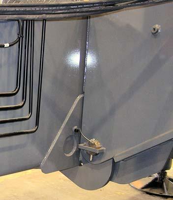
4. As necessary, separate or connect the quick disconnects.
5. Immediately close the bleed valve.
6. Restart the engine if necessary.
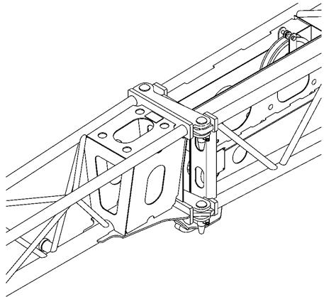
Outrigger Box Removal
1. Remove the quick release pins (1) Figure4-20 from the ends of each of the pinning cylinder rod ends.
2. Using the crane boom for the lifting operation, fasten lifting slings to the lifting lugs provided on each end of the outrigger box.
3. Lift the outrigger box enough to remove the pressure off of the ends of the pinning cylinder rod ends.
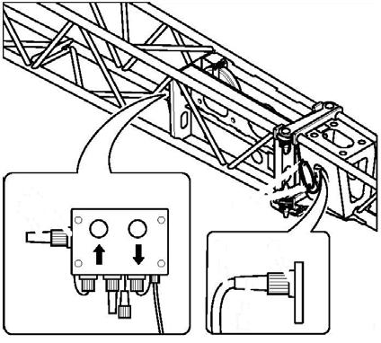
CAUTION!
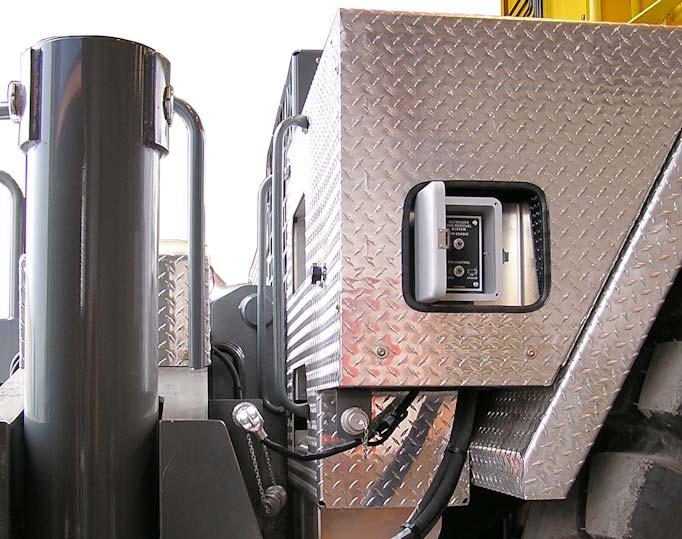
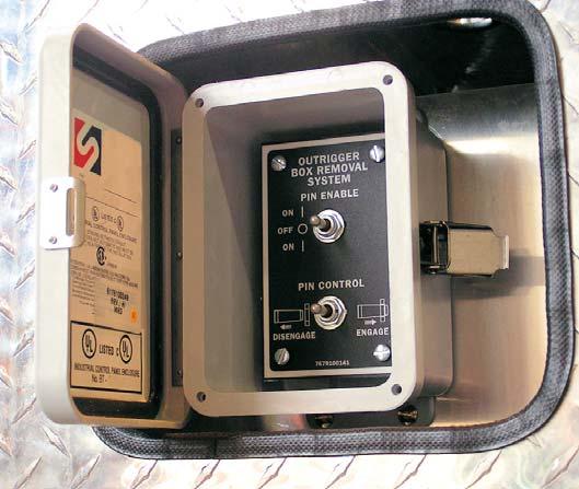
Do not activate any switches on the control in (Figure4-22) until you are thoroughly fam iliar with the outrigger box installation and removal procedure.
4. Using the appropriate outrigger box removal control: either in the left front fender for the front outrigger box or in the right rear fender for the rear outrigger box, hold the Pin Enable switch to the ON position (Figure4-22) and push the Pin Control switch to DISENGAGE until the pinning cylinder rods are fully retracted.
8. Stow the retainer pins in the stowage clamps on the outrigger box.
9. Stow the electrical connector in the plug provided on the fender.
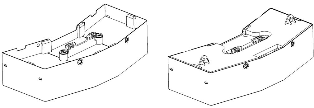
Outrigger Box Installation
NOTE: Outrigger boxes are not interchangeable front to rear or with outrigger boxes from another crane. The outrigger box assembly weighs approximately 9427 lb (4276 kg).
1. Make sure the outrigger pressure bleed valve is closed.
2. Connect sling assembly to the lifting lugs provided on each end of the outrigger box (Figure4-21).
3. Lift and align the outrigger box close to the installed position at the rear or front of the carrier, as applicable.
4. Connect the carrier external electrical connector to the outrigger external connection.
5. Install the carrier hydraulic quick disconnects to the external connections of the outrigger box.
6. Lower the outrigger box aligning the pinning cylinder pins with the attach points on the carrier frame.
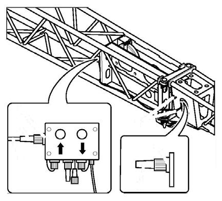
CAUTION!
Do not activate any switches on the control (Figure4-22) until you are thoroughly familiar with the outrigger box installation and removal procedure.
5. Disconnect the carrier external electrical connector from the outrigger external connection.
6. Disconnect the carrier hydraulic quick disconnects from the external connections of the outrigger. Stow the carrier lines inside the fender.
7. Lift the outrigger box from the carrier.
7. Using the appropriate remote mounted pin control box, hold the Pin Enable switch at the ON position and hold the Pin Control switch to the ENGAGE position (Figure4-22).
8. After the pinning cylinders have fully engaged the outrigger box, install a quick release pin in the end of each of the cylinder rod ends (1) (Figure4-20).
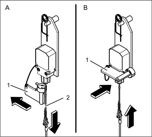
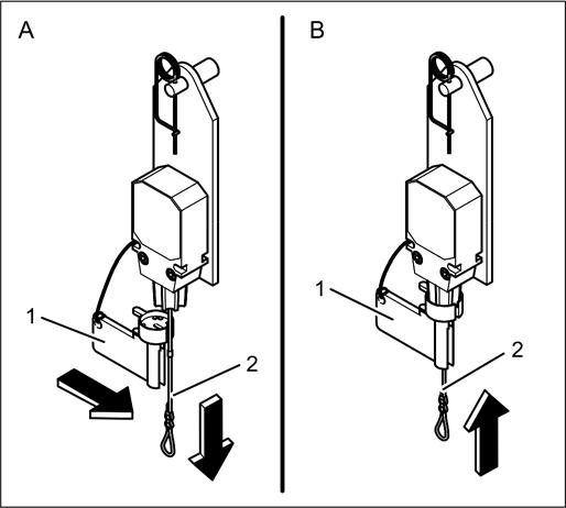
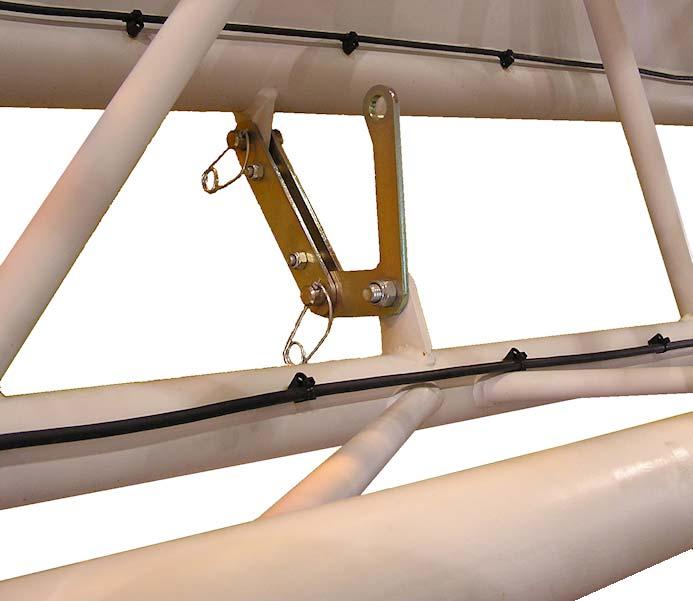
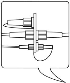
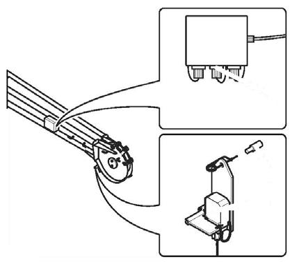
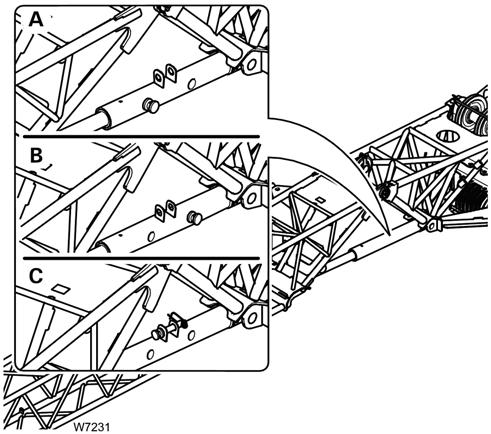
ANTI TWO BLOCK (A2B) SWITCH
If a hoist rope has been reeved and two A2B switches are installed, the unused A2B switch must be locked (disabled) to allow all crane operations.
Lock
Caution
If the A2B switch is locked (disabled), the hook block could hit the main boom head or extension, resulting in damage to the hook block, main boom head or extension, and hoist rope. Never lock an A2B switch with a switch weight attached.
1. Remove A2B weight.
2. (A) Remove cap (1) from switch.
3. Pull lanyard (2) down.
4. (B) Secure lanyard (2) in this position using cap (1). A2B switch is locked (disabled).
Before Operation
Check the following electrical connections before operating the crane to ensure the LMI system is properly connected for the crane configuration.
Cranes With Main Hoist Only
If the crane is operated only with the boom and without boom extension or lattice extension, no additional connections are necessary. It must however be ensured that the A2B switch weight is correctly mounted on the main boom hoist rope. With even numbers of rope lines, the lifting limit switch weight shall be attached to the "dead end" of the hoist rope. With odd numbers of rope lines, the lifting limit switch weight shall be attached to the rope line with the lowest operating speed.
Unlock
NOTE: Always remove the switch lock (enable) before installing an A2B weight around the hoist rope.
1. (A) Pull down lanyard (2) and remove cap (1). Switch is unlocked (enabled).
2. (B) Install cap (1) on A2B switch.
If the crane is operated with a main boom extension or top section, the connecting cable must be mounted between the distributor socket on the lattice extension and the distributor socket on the main boom. The main boom A2B switch weight must be disconnected and mounted on the extension or fly boom A2B switch.
Warning
Failure to reposition the A2B weight will prevent the A2B system from functioning properly. No weight shall be mounted on the A2B switch of the main boom when working with the extension/top section.
Machines with Main and Auxiliary Hoists
If the main boom extension or fly section is not used, then the bridging plug must be plugged into the distributor socket on the main boom and the lifting limit switch we ight must be mounted on the main boom.
If the crane is operated with a main boom extension and/or with a lattice extension, then the connecting cable must be mounted between the distributor socket on the extension or on the top section and the distributor socket on the main boom. In addition, weights must be fitted to both the A2B switch of the main boom and the extension or fly section.
If the boom extension or lattice extension are in working position and if the main boom is not equipped with a hoist rope, then the weight of the A2B switch on the main boom must be removed to prevent endangering personnel or damaging equipment.
After electrical connections have been checked to ensure the system is properly connected for the respective crane configuration, the following checks must be made:
1. Check electrical wiring connecting various parts of the system for physical damage.
2. Check A2B switches and weights for free movement.
3. Inspect spring cable drum for smooth running, initial drum tension, and correct cable winding.
4. Inspect mechanical and electrical installation of power measurement sockets on the lattice extension (if present).
Warning
The following tests must be performed with care to prevent personnel injury or crane damage. Proper functioning of the CCS requires successful completion of these tests before starting work.
If the operator cannot see the hook block approaching the pulley head, this task must be assigned to an assistant (slinger).
The crane operator must be prepared to stop the crane immediately if the CCS is not working correctly, i.e. when warning indicators do not display, the acoustic alarm does not sound, and crane movements such as raising, extending and luffing are not disabled.
Check Hoist limit switch warning light and acoustic alarm as follows:
1. Manually raise weight fitted on the A2B switch. As soon as weight is raised, the acoustic alarm should sound and A2B switch warning should display.
2. Using the main hoist, pull hook block slowly against the A2B switch weight. As soon as the hook block raises the weight, the acoustic alarm should be triggered, the A2B switch warning should display, and the main hoist should switch off. Lower the hook block slightly to eliminate this condition.
3. Slowly lower the boom to bring about a potential hoist limit situation. As soon as the hook block raises the weight, the acoustic alarm should sound, the A2B switch warning should display, and the luffing gear should switch off. Lower the hook block slightly to eliminate this condition.
4. Slowly extend (telescope out) the boom to bring about a potential hoist limit situation. As soon as the hook block raises the weight, the acoustic alarm should sound, the A2B switch warning should display, and the telescoping function should switch off. Lower the hook block slightly to eliminate this condition.
Warning
If warning indicators and audible alarm do not function as described and crane movements are not switched off, the system is not working properly. The malfunction must be corrected before starting work.
5. If crane is equipped with a main boom or lattice extension, the inspection procedure must be repeated for the A2B switch of the extension/top section.
6. Check display of main boom length agrees with actual boom length.
7. Check display of main boom angle agrees with actual boom angles.
8. Check display of the crane operating radius agrees with the actual radius.
9. Check load display by lifting a load of known weight. Load display accuracy must be within the tolerance range.
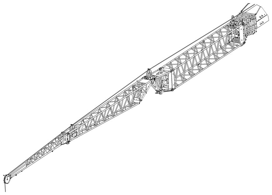
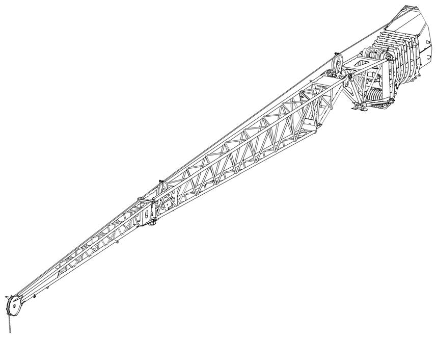
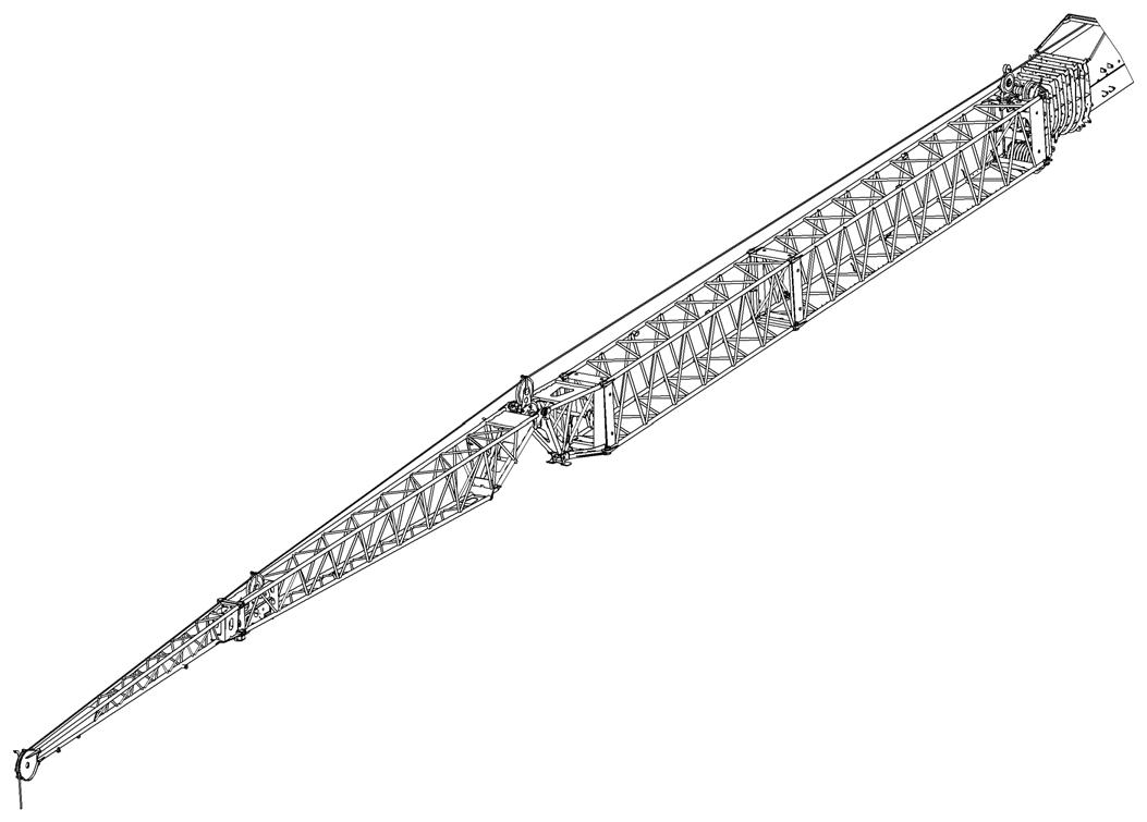
Boom Extensions
Refer to Figure4-25 for a diagram of the boom extensions available for this crane.
The RT9150E can be used with the following boom extensions:
• 36 ft to 59 ft (11 m to 18 m) manual offsettable bi-fold swingaway boom extension (folding manual luffing extension), with mechanical offset mechanism for offsets of 0, 20, & 40 degrees, as standard—unless it was explicitly not ordered.
• 36 ft to 59 ft (11 m to 18 m) hydraulic offsettable bi-fold swingaway boom extension (folding hydraulic luffing extension), with hydraulic offset mechanism for offsets of 0 to 40 degrees.
• 11.8 ft (3.6 m) heavy duty six-sheave hydraulic offsettable boom extension (heavy duty extension), with hydraulic offset mechanism for offsets of 0 to 40 degrees.
• 26 ft. (8 m) base extension insert (26 ft insert) to use with any of the 36 ft. to 59 ft. (11 m to 18 m) folding extensions.
• 19.6 ft. (6 m) extension insert (20 ft insert) to be used with the 26 ft insert and any of the folding extensions.
All boom extensions are built specifically for the crane with which they were sold. Each extension is stamped with the crane’s serial number.
Caution
Equipment Damage Hazard!
Operate the crane only with extensions which have the same serial number as the crane, to prevent malfunctions and damage to the equipment.
To use extensions on several Grove cranes, the extensions and cranes must be adjusted. Label all extensions with the respective crane serial numbers.
Caution
Have the adjustment of the boom extension carried out only by Manitowoc Crane Care.
Installing the Folding Boom Extension
Danger
To prevent serious injury or death, always wear personal protective equipment; i.e., a hard hat, eye protection, gloves and metatarsal boots.
1. Before installing the boom extension make sure the crane is set up on outriggers using normal setup procedures. Refer to Deploying the Outriggers, page 3122
NOTE: An auxiliary crane with sling is required to install the boom extension.
2. Rotate the superstructure so the boom is over the front.
3. Retract and lower the boom to horizontal.
4. Attach a tag line to the junction of the 36 ft and 23 ft extensions.
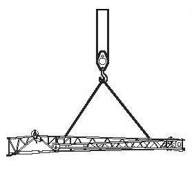
5. Using a sling attached to an auxiliary crane, lift the extension in front of the main boom (Figure4-26).
8. While maintaining control with the tag line, swing extension into position on boom nose.
9. Remove the pins out of the holders (1) (Figure4-28). Install the pins (2) into the mounting lugs (3) and secure with the retaining clips.
NOTE: If the pins cannot be inserted, the strain can be taken off the connecting points. Refer to Relieving the Load on Connecting Lugs, page 4-26
6. Align the extension left side mounting lugs (1) to the boom nose right side mounting lugs (2) (Figure4-27).
7. Install the pins (3) through the mounting lugs and secure with the retaining clips.
To stow the entire 59 ft folding extension on the main boom, refer to the Stowing Procedure: 59 ft (18 m) Extension, page 4-41
To erect just the 36 ft extension, refer to Stowing Procedure: 23 ft (7 m) Boom Extension, page 4-40.
To erect the 59 ft extension, continue with the follow steps.
10. Establish electrical connections between the extension and the main boom, refer to 59 ft (18 m) Extension Electrical Connections, page 4-32
11. Install the limit switch, refer to 59 ft (18 m) Extension A2B Installation, page 4-33
12. For units equipped with a hydraulic luffing extension, establish hydraulic connections between the extension and the main boom, refer to Establishing the Hydraulic Connection, page 4-35
NOTE: You can also install the folding boom extension in front of the inserts when changing from a 59 ft extension to a longer boom extension.
Securing Extension with Tag Line (Rope)
DANGER Crushing Hazard!
Always secure the boom extension with a tag line (rope) on the main boom before removing any connections. This will prevent the extension from slipping off the run-up ramp, swinging around and knocking you off the carrier or injuring other persons in the swing range.
Before actuating swing or any other function, sound horn and verify that all personnel are clear of rotating and moving parts.
7567-10
FIGURE4-29
When installing or removing the pins and the connecting lugs do not align:
1. Lower the boom until the nose of the extension is on the ground or suitable support (1) (Figure4-29). If necessary, override the lifting limit switch.
2. Continue to lower carefully until the connecting points align or until the load has been removed from the pins.
Extension Erecting Warnings and Requirements
Death or serious injury could result from being crushed by moving machinery. Before attempting to erect or stow the boom extension, read and strictly adhere to all danger decals installed on the extensions and stowage brackets.
The extension may swing out on its own when the last connection is removed that held the extension at the side of the main boom.
The extension must be secure before beginning the erection procedure.
Secure the extension as follows:
• Attach a tag line at the front of the extension.
• Guide the tag line underneath the extension and through a bracket on the main boom and back again.
• Have a helper hold the tag line tight while removing the last connection.
NOTE: If alone, secure the other end of the tag line on the crane (e.g. on the steps of the access ladder to the carrier or to the hole in the superstructure). Leave enough play in the tag line that it is tight only when you swing the lattice extension towards the main boom head later on.
Relieving the Load on Connecting Lugs
NOTE: The weight of the extension can cause the connecting lugs on the left side to be misaligned or the pins to become wedged which makes it difficult to install or remove the pins.
Danger
Crushing Hazard!
Before you erect a boom extension, the following requirements must be met:
• The folding extension is mounted on the side of the main boom and is in the transport condition.
• The crane is level, supported on outriggers according to the Load Chart for the planned operation with the configured extension.
• The main boom is completely retracted and has been lowered into a horizontal position.
Erecting Procedure: 36 ft (11 m) Extension
This procedure is for erecting just the 36 ft extension, leaving the 23 ft extension attached to the main boom.
Warning
Falling Hazard!
To prevent serious injury or death, do not stand on decking until extensions are secure.
1. Visually check to ensure all pins securing the extension are installed.
NOTE: The crane should be setup on outriggers using normal setup procedures. Refer to Deploying the Outriggers, page 3-122 a. Guide the tag line around the end of the extension and through the bracket (4) (Figure4-32) on the main boom and back again. b. If possible, have a helper hold the tag line tight while releasing the connections.
2. Retract and lower boom to horizontal for erecting over the front of the crane.

3. Attach a tag line (3) (Figure4-32) at the front of the extension.
4. Release the spring latch (1) (Figure4-30). Fold out the run-up ramp (2) until the locking pin (3) engages the tab (4).
Danger
Crushing Hazard!
Before disconnecting the locking bar and rear pins, ensure the extension is secured with the tag line, is on the run-up ramp and attached at the front latch. This will prevent extens ions from falling when disconnected, causing death or serious injury.
6. Remove the retainer clips (1) (Figure4-32) and pull pins (2) out of connecting points. Insert pins into holder and secure with retainer clips.
5. Remove the pin (1) (Figure4-31) from the locking bar (2). Move the locking bar (2) to the base section attachment bar (3) and install pin. Secure with retaining clip.
CAUTION Falling Objects Hazard!
Ensure the extension connecting pins are always secured with retaining clips. This prevents unsecured pins from becoming loose and falling out causing injuries.
12. Using the jib extension pole, disengage the front latch assembly by pushing handle (3) (Figure4-34) up and onto the handle rest (4).
13. While maintaining control of the extension with the tag line, disconnect the tag line from the main boom.
7. Using the tag line, pull the front of the extension until the extension mounting lugs (2) (Figure4-33) align with the boom head lugs (1).
8. Using a ladder or suitable lifting device, remove the retainer clips (3) and pull the pins (4) out of the holders (5). Install the pins through the connecting lugs and secure with the retainer clips.
9. Have a helper hold, or make secure, the front of the extension against the main boom.
10. Using a ladder or aerial work platform, use the jib extension pole, located in the cab, to pull the retaining clip out of the horizontal locking pin (1) (Figure4-34).
11. Use the jib extension pole to pull the horizontal locking pin out of the front latch assembly and place in the storage lugs (2). Secure with the retaining clip.
Danger
Crushing Hazard!
To prevent serious injury or death, do not release the front latch without the extension being secured with a tag line at the other end.
To prevent serious injury or death, do not stand in the swing arch of the extension.
14. Use the tag line to pull the extension off the ramp.
15. While maintaining control with the tag line, swing extension into position on boom nose. The 23 ft (7 m) section will remain on the boom.
NOTE: If the extension doesn’t easily swing around to the front, slightly lower the boom from horizontal.
16. Using a ladder or suitable lifting device, remove the retainer clips and pull the pins out of the holders (1) (Figure4-35). Install the pins (2) into the connecting lugs (3). Secure with the retainer clips.
NOTE: If the pins cannot be inserted, the strain can be taken off the connecting lugs, refer to, Relieving the Load on Connecting Lugs, page 4-26
Erecting Procedure: 59 ft (22 m) Extension
The 59 ft extension includes the 36 ft extension with the 23 ft extension unfolded and attached to the nose of the 36 ft extension.
Warning
Falling Hazard!
To prevent serious injury or death, do not stand on decking until extensions are secure.
1. Visually check to ensure all pins securing the extension are installed.
NOTE: The crane should be setup on outriggers using normal setup procedures. Refer to Deploying the Outriggers, page 3-122 a. Guide the tag line around the end of the extension and through the bracket (4) on the main boom and back again. b. If possible, have a helper hold the tag line tight while releasing the connections.
2. Retract and lower boom to horizontal for erecting over the front of the crane.
3. Attach a tag line (3) (Figure4-37) at the front of the extension.
4. Release the spring latch (1) (Figure4-36). Fold out the run-up rail (2) until the locking pin (3) engages the tab (4).
Danger
Crushing Hazard!
Before disconnecting the rear pins, ensure the extension is secured with the tag line, is on the run-up ramp and attached at the front latch. This will prevent extens ions from falling when disconnected, causing death or serious injury.
5. Remove the retainer clip (1) (Figure4-37) and pull the pin (2) out of connecting lug. Insert pin into holder and secure with retainer clip.
CAUTION Falling Objects Hazard!
Ensure the extension connecting pins are always secured with retaining clips. This prevents unsecured pins from becoming loose and falling out causing injuries.
6. Using the tag line, pull the front of the extension until the extension mounting lugs (2) (Figure4-38) align with the boom head lugs (1).
7. Using a ladder or suitable lifting device, remove the retainer clips (3) and pull the pins (4) out of the holders (5). Install the pins through the connecting lugs and secure with the retainer clips.
8. Have a helper hold, or make secure, the front of the extension against the main boom.
9. Using a ladder or aerial work platform, use the jib extension pole, located in the cab, to pull the retaining clip out of the horizontal locking pin (1) (Figure4-39).
10. Use the jib extension pole to pull the horizontal locking pin out of the front latch assembly and place in the storage lug (2). Secure with the retaining clip.
DANGER Crushing Hazard!
To prevent serious injury or death, do not release the front latch without the extension being secured with a tag line at the other end.
11. Using the jib extension pole, disengage the front latch assembly by pushing handle (3) (Figure4-39) up and onto the handle rest (4).
12. While maintaining control of the extension with the tag line, remove the tag line from the bracket (4) (Figure4-37) on the main boom.
Warning
Crushing Hazard!
To prevent serious injury or death, do not stand in the swing arch of the extension. Be aware that if the boom is lowered the extension will swing out on its own if not secured with the tag line.
13. Use the tag line to pull the extension off the ramp.
14. While maintaining control with the tag line, swing extension into position on boom nose.
NOTE: If the extension doesn’t easily swing around to the front, slightly lower the boom from horizontal.
15. Using a ladder or suitable lifting device, remove the retainer clips and pull the pins out of the holders (1) (Figure4-35). Install the pins (2) into the connecting lugs (3). Secure with the retainer clips.
NOTE: If the pins cannot be inserted, the strain can be taken off the connecting lugs, refer to, Relieving the Load on Connecting Lugs, page 4-26
16.
Warning
Crushing Hazard!
Always secure the 23 ft extension with a tag line before releasing the connection between the two extensions. This will prevent the 23 ft extension from swinging uncontrolled, causing serious injury or death.
18.
19. Remove the retaining clip (1) (Figure4-41) from the pin (2) and remove the pin. Secure the locking bar (3) to the stowage lug (4) on the 36 ft (11 m) extension with the pin and retainer clip.
Warning
Crushing Hazard!
To prevent serious injury or death, do not stand in the swing arch of the extension.
20. Using the tag line (Figure4-42) to maintain control, swing the 23 ft (7 m) extension into the erected position.
NOTE: Do not lower boom until the 23 ft extension has been completely swung in front of the 36 ft extension.
21. Slightly lower the boom.
22. Remove retainer clips and pins (Figure4-42) from holder. Install pins (1) in connecting lugs and secure with retainer clips (2).
Extension Electrical Connections
To connect the anti-two block (A2B) switch, aircraft warning light or anemometer to boom extensions the following procedures must be performed.
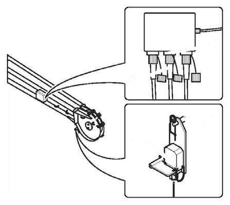
36 ft (11m) Extension Electrical Connections
The following procedure connects the 36 ft extension wiring to the main boom circuits. This connection must be made in order to connect the 59 ft extension wiring and to connect to an anti-two block switch.
1. Remove the bridging plug (1) from socket (3) and plug it into the storage socket (2) (Figure4-43).
2. Remove the plug (4) from the storage socket (5) and unwind the cable from the storage location (6). Connect the plug (4) to the socket (3).
This connects the extension to the main boom circuit.
3. Wind the cable around the storage location (6) such that it will not be damaged during crane operation.
59 ft (18 m) Extension Electrical Connections
The following procedure connects the 23 ft (7 m) extension wiring to the 36 ft (11 m) extension wiring for operation of the 59 ft (18 m) extension. This connection must be made in order to connect any electrical devices and an anti-two block switch.
1. Remove the bridging plug (5) (Figure4-44) from the socket (1).
2. Unwind the cable (3) from the storage location (6).
3. Remove the plug (2) from the storage socket (4) and unwind the cable (3) from the storage location (6). Connect plug (2) into the socket (1).
This makes the connection from the 23 ft (7 m) extension to the 36 ft (11 m) extension for use of the 59 ft (18 m) extension.
4. Plug the bridging plug (5) into the storage socket (4).
5. Wind the cable (3) on the storage location (6) so that it will not become damaged.
Disconnect Electrical Connections to the 59 ft (18 m) Section
1. Remove the plug (2) from the socket (1) and plug it into the dummy socket (4) (Figure4-45).
2. Wind the cable (3) onto the storage lugs (6).
3. Remove the bridging plug (5) from the dummy socket (4) and plug it into the socket (1).
Connecting the Anti-Two Block Switch
36
ft
(11 m) Extension A2B Installation
To electrically connect the A2B switch the electrical connections to this extension must be completed, refer to 36 ft (11m) Extension Electrical Connections, page 4-32.
The A2B switch can now be moved to another location and connected.
59 ft (18 m) Extension A2B Installation
To electrically connect the A2B switch the electrical connections to this extension must be completed, refer to 59 ft (18 m) Extension Electrical Connections, page 4-32
1. Install the A2B switch assembly (5) (Figure4-46) on to the pin (4) and secure it with a retaining clip.
2. Remove the bridging plug (3) from the socket (1) and plug it into the storage socket (2), as shown.
3. Route the cable (6) so that it will not be damaged during crane operation, and connect the A2B connector (7) to the socket (1).
36 ft (11 m) Extension A2B Removal
When the extension is no longer needed or if installing the 23 ft extension for 59 ft extension operation, the A2B switch must be removed.
1. Remove the A2B connector (7) from the socket (1).
2. Connect the bridging plug (3) into the socket (1).
3. Install the cap on the storage socket (2).
4. Remove the retaining clip from the mounting pin and remove the A2B assembly.
1. Install the A2B switch (3) on to the pin (2) and secure it with a retaining clip (Figure4-47).
2. Route the A2B cable (4) such that it will not be damaged during crane operation, and connect the A2B switch to socket (1).
59 ft (18 m) Extension A2B Removal
1. Remove the plug from the socket (1) (Figure4-48).
2. Remove the A2B switch assembly (3) from the pin (2).
3. Fasten the retaining pin to the lifting limit switch.
Extension Hydraulic Connections (Optional
Hydraulic Extension)
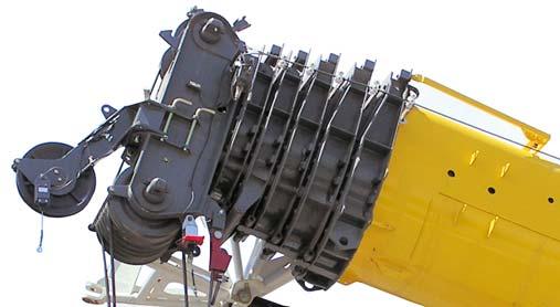
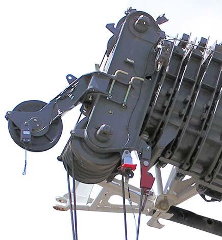
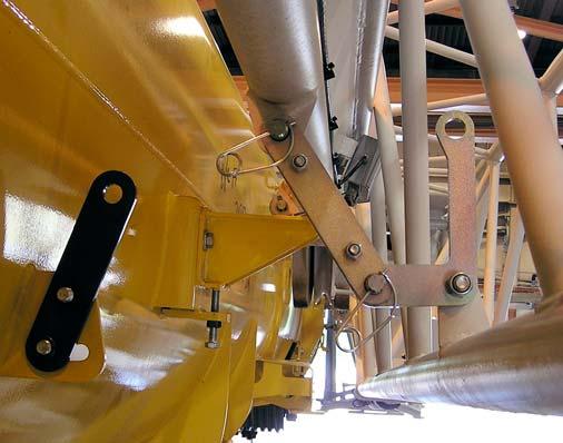
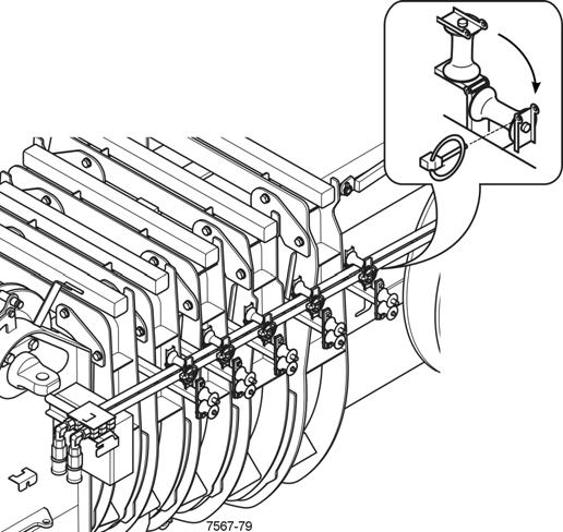
Disconnect the hydraulic lines from the boom nose whenever the operation of the crane does not require hydraulic power. This will extend the life of the hose drum, hoses, and associated hardware.
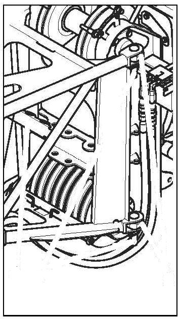
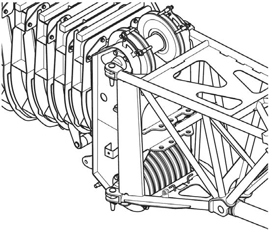
Checking the Locking Device on the Hose Drum
The hose drum on the side of the main boom provides the hydraulic supply to the boom nose/luffing jib. The hose drum is equipped with a locking device. The drum must be unlocked before operation.
If the hose drum has to be removed, the drum must be locked.
Caution
Equipment Damage Hazard!
Always verify the drum is unlocked before using extensions or other equipment that require hydraulic power. Damage to hydraulic hoses or the boom may occur.
Caution
Spring Loaded Equipment Hazard!
The drum must be locked before removal. The drum is spring loaded and must be locked to prevent damage or injury.
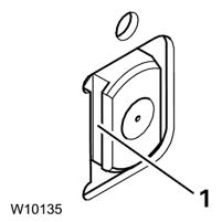
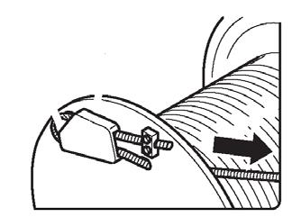
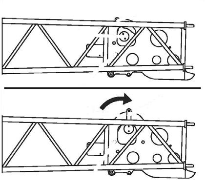
Holes (1) (Figure4-49) are distributed on the inner wheel of the hose drum. Rotating the latch (2) engages one of the holes to lock the drum, preventing it from turning.
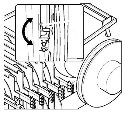
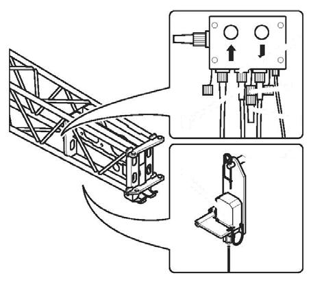
Unlocking the Drum
Rotate the latch (2) clockwise (A), to disengage it from the hole.
Locking the Drum
1. Turn the hose drum until a hole is aligned with the latch (2).
2. Rotate the latch (2) counterclockwise to position (B), until the latch fully engages the hole.
Caution
Spring Loaded Equipment Hazard!
If the strain relief is detached after the locking device has been released, do not under any circumstances let go of the strain relief before it has been re-attached. If you let go of the strain relief, the hydraulic hoses will spring back uncontrollably due to the spring force in the hose drum and may injure persons or damage parts of the crane.
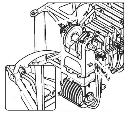
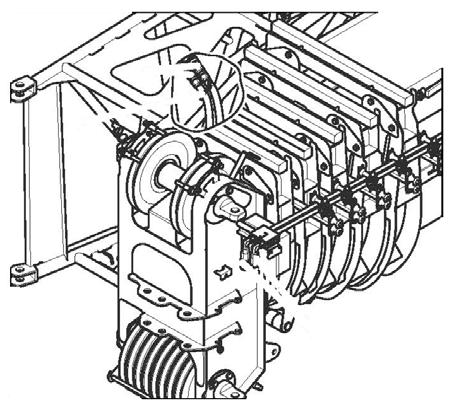
Hydraulic Hose Installation
1. Unlock the hose drum.
2. Remove the hinged pins (1) (Figure4-50) and fold up the guide sheaves (2).
3. Remove the strain relief (3) from its main boom mounting bracket (4) and pull the hydraulic hoses (5) towards the boom nose.
4. Hook the strain relief onto the boom nose mounting bracket (6).
5. Fold down the guide sheaves (2) and secure them with the hinged pins (1).
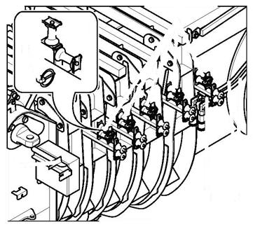
Position for Main Boom Operation
The locking device on the hose drum must be undone:
1. Loosen the hinged pins (5) (Figure4-51) and fold up the guide sheaves (4).
2. Detach the strain relief from the holder (3) and attach it to the holder (2).
3. Fold down the guide sheaves (4) and secure them with the hinged pins (5).
Establishing the Hydraulic Connection
1. If necessary, bring the connections (1) (Figure4-52) into the position for lattice extension operations on page 434.
2. Remove the hose line (2) from the clamp (4).
3. Feed the hose lines towards the left hand side through the lower opening (3) in the 36 ft (11 m) section under the boom head.
4. Remove the protective caps to the connections (1) and attach the hose lines (observe color code).
Disconnecting the Hydraulic Connection
1. Remove the retaining clip from the pin (2) (Figure4-54).
1. Remove the hose lines (2) from the connections (1) (Figure4-53).
2. Close off the hose lines and the connections (1) with the protective caps.
3. Secure hoses in holder (1) on the 11 m (36 ft) extension.
Folding Deflection Sheaves
Deploying the Rear Deflection Sheave
Caution
Pinch Hazard!
Always hold the deflection sheave by the handle when removing the pin. You might get your fingers crushed if you hold the sheave by the side plates.
2. Hold the deflection sheave by the handle (1) and pull out the pin (2).
3. Fold the deflection sheave (3) up and fasten it in this position with the pin (2).
4. Secure the pin (2) using the retaining clip.
Stowing Rear Deflection Sheave
1. Remove the retaining clip from the pin (2) (Figure4-54).
2. Hold the deflection sheave by the handle(1) and pull out the pin (2).
3. Fold the deflection sheave (3) down and fasten it in position with the pin (2).
4. Secure the pin (2) using the retaining clip.
Deploying the Front Deflection Sheave
Positioning/Removing the Hoist Cable Positioning Hoist Cable
Caution
Falling Objects Hazard!
Always make sure sheaves and pins that secure the hoist cable are secured with clips. This prevents components from coming loose, falling and causing injury.
1. Remove the retaining sheaves (1) (Figure4-56).
2. Guide the wire rope over the deflection sheaves (4), (3) and over the nose sheave (2) of the extension.
3. Reinstall all the retaining sheaves (1) and secure with retaining clips.
1. Remove the retaining clip from the pin (2) (Figure4-55).
2. Hold the deflection sheave by the strut (1) and pull out the pin (2).
3. Fold the deflection sheave (3) up and fasten it in this position with the pin.
4. Secure the pin (2) using the retaining clip.
Folding In Front Deflection Sheave
1. Remove the retaining clip from the pin (2) (Figure4-55).
2. Hold the deflection sheave by the strut (1) and pull out the pin (2).
3. Fold the deflection sheave (3) down and fasten it in position with the pin (2).
4. Secure the pin (2) using the retaining clip.
4. Install the hook tackle or the hookblock. The wire rope may now be reeved once or twice, depending on the length of the section.
Removing Hoist Cable
1. Unreeve the hookblock.
2. Remove the retaining sheaves (1) (Figure4-56).
3. Take the wire rope off the head sheave (2) and deflection sheaves (4), (3) and place it on the ground on the left side.
4. Replace all retaining sheaves and secure them with retaining clips.
Mechanical Luffing Jib (Adjustable Boom Extension)
Extension Angle Adjusting Mechanism
Warning
Crushing Hazard!
Always secure the adjustable boom extension with an auxiliary crane or set the nose of the extension on the ground before you remove the adjusting pins when adjusting the angle of the jib.
This prevents the extension from suddenly unfolding and causing serious injury or death.
Caution
Risk of Equipment Damage!
Always fold up the deflection sheave before adjusting the luffing jib angle.
This will prevent any interference between the deflection sheave and extension.
Refer to Figure4-57.
FIGURE4-57
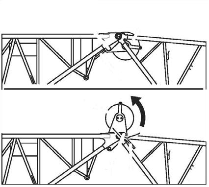
The jib angle is determined by the position of the adjusting pin. There are three positions:
•0° angle: (A) – For a 0° angle, the pin (1) is installed in the front location and is secured with the retaining clip.
•20° angle: (B) – For a 20° angle, the pin (1) is installed in the rear location and is secured with the retaining clip.
•40° angle: (C) – For a 40° angle, the pin (1) is removed and stored in the holder (2) and secured with the retaining clip.
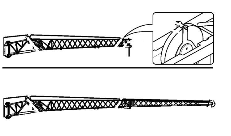
Setting the Angle with an Auxiliary Crane
NOTE: The information in this section only applies to the mechanical luffing jib. For operation of the hydraulic luffing jib, refer to Raising and Lowering the Hydraulic Boom Extension, page 3-154
If an auxiliary crane is available, the boom extension can be slung to set the angle.
If no auxiliary crane is available, refer to Setting the Angle without an Auxiliary Crane, page 4-38
1. Lift the extension with the auxiliary crane until the pin (1) (Figure4-57) is relieved of load.
2. Lift or lower the extension with the auxiliary crane until the adjusting pin can be installed into the position for the required angle, refer to Extension Angle Adjusting Mechanism, page 4-38
3. Lower the extension with the auxiliary crane and remove the lifting gear.
If the lattice extension now touches the ground at the current angle, the angle will set itself when the main boom is raised.
Setting the Angle without an Auxiliary Crane
If an auxiliary crane is not available, the extension head must rest on the ground before the angle is changed.
Warning
Tipping Hazard!
Always enter the RCL rigging code for the current rigging mode of the crane. Only rotate the superstructure into the working position permitted by the RCL rigging code set according to the Load Chart
This prevents the crane from overturning when the main boom is extended.
The telescoping range which is enabled for the rigging code is only permissible fo r telescoping without a load and without hookblock/hook tackle.
When the main boom is fully extended, load measurement is not possible and the RCL monitoring depends on the working radius. For this reason, you must unreeve the hookblock. This prevents the crane from overturning when the main boom is extended. Serious injury or death may occur should the crane tip or overturn.
Caution
Risk of Damage to the Wire Rope!
Unreeve the hook block and lay the hoist cable beside the boom extension before you set the angle of the extension. This prevents the cable from being damaged when the head of the extension is set on the ground.
Entering the RCL Code
Enter the RCL rigging code for the boom extension angle in accordance with the current rigging mode of the crane, refer to the Load Chart, Chapter Remarks.
When adjusting the angle without an auxiliary crane, you must enter an RCL rigging code, refer to Entering the Rigging Mode, page 3-81. The RCL rigging code depends on:
• the rigged outrigger span
• the rigged counterweight
• the working position.
The superstructure must be in a working position permitted by the Load Chart for the RCL rigging code that was entered.
Setting an Angle of 20° or 40°
This section assumes that the extension has been pinned in front of the main boom and the unreeved cable has been laid beside the extension.
1. Enter the RCL rigging code for the extension angle, refer to Entering the Rigging Mode, page 3-81.
2. Extend the main boom as far as is permitted for the RCL rigging code set, or as far as possible given the space available.
3. Lower the main boom until the lattice extension head touches the ground.
4. If the ground cannot be reached, you can incline the crane further, refer to Inclining the Crane, page 4-39
NOTE: In the steps which follow, the extension head is pulled or pushed over the ground. Lay boards or similar under the skids on the extension head so that it is not damaged.
Warning
Crushing Hazard!
If the extension is lowered onto timbers or some other structure to set the angle, keep in mind that as the extension is raised the extension head will slide towards the crane until the set angle is reached. The extension could slip off an unsuitable structure, fold down and cause serous injury or death.
5. If necessary, relieve the load on the adjusting pin (1) (Figure4-57) by lowering the boom slightly.
6. Raise or lower the main boom so the pin (1) can be inserted into the position for the angle required, refer to Extension Angle Adjusting Mechanism, page 4-38.
7. Raise the main boom slowly until the extension head is no longer touching the ground. The head of the extension will be pulled across the ground.
8. The extension will then be inclined by the angle set.
9. If you inclined the crane using the outriggers in order to set the angle, align it to the horizontal again.
10. Fully retract the main boom. While doing so, the lattice extension must not touch the ground; raise the boom as necessary.
11. Set down the head of the lattice extension on the ground.
12. If you inclined the crane using the outriggers, align it to the horizontal now so that the lattice extension sections can be folded more easily.
Inclining the Crane
In order to set the angle of the adjustable extension, you must set it down on the ground by extending and lowering the main boom.
Depending on the space availa ble, the condition of the terrain or a limitation on the telescoping due to the current rigging mode, it may be that the head of the extension cannot be set on the ground by telescoping and lowering the main boom.
In this case, you can use the outriggers to incline the crane.
1. Fully extend the rear outriggers and jack cylinders.
2. Fully extend the front outriggers.
3. Extend the front jack cylinders to raise the front wheels off the ground.
Warning
Tipping Hazard!
Make sure that the wheels do not touch the ground when the crane has been inclined. This prevents a reduction in the stability of the crane, which could lead to it tipping over when setting the angle of the lattice extension, causing serious injury or death.
Stowing the Folding Boom Extension Requirements for Stowing the Boom Extensions
Before lowering a boom extension into a horizontal position, the following requirements must be met:
• No other load is raised apart from the hookblock.
• The counterweight required, according to the Load Chart for the planned operation with the configured extension, is rigged.
• The crane is supported with the outriggers prescribed for operation with the extension according to the Load Chart
• The main boom is fully retracted.
Danger
Crushing and/or Tipping Hazard!
To prevent serious injury or death, do not stand on decking until extensions are secure.
Do not override the RCL when lowering the boom into a horizontal position.
If the RCL is overridden, the crane operations will not be monitored and the crane may overturn if outside of the permissible working range.
• Retract the main boom completely, and lower boom to the horizontal position.
• Remove the A2B switch weight and A2B switch, refer to Connecting the Anti-Two Block Switch, page 4-33
• Unreeve the cable and remove it from the extension. Refer to Positioning/Removing the Hoist Cable, page 437
• Fold in the deflection sheaves at the front and rear. Refer to Folding Deflection Sheaves, page 4-36
Stowing Procedure: 23 ft (7 m) Boom Extension
The 23 ft extension can be folded to the side of the 36 ft extension or stowed on the main boom.
1. Attach tag line to the nose of the 23 ft (7 m) section. If working alone, route the tag line through the left side of the 36 ft section and secure it to the lattice framework. This will prevent the 23 ft (7 m) extension from swinging around uncontrolled.
Warning
Crushing Hazard!
To prevent injury or death, ensure there are no people or objects in the swing area of the extension.
If working alone, secure the rear of the 23 ft (7 m) extension to the front of the 36 ft (11 m) section using the tag line or a second rope.
2. Remove the retaining clips from the pins (1) and remove the pins from the connecting lugs (Figure4-58).
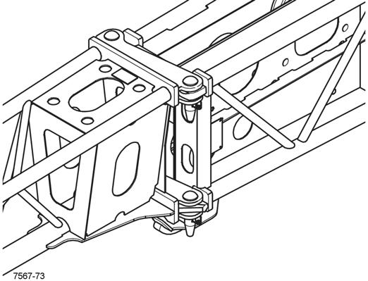
3. Install the pins (1) into the holder (2) and secure with retaining clips.
4. Using the tag line to control movement of the extension, swing it into the stowed position on the side of the 36 ft (11 m) extension.
5. Secure the 23 ft (7 m) extension to the 36 ft (11 m) extension with the locking bar (1) (Figure4-59) and pins (2).
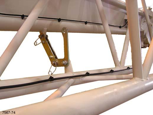
6. Secure the pins with the retaining clips.
NOTE: If the 23 ft (7 m) extension is being stowed on the main boom and the 36 ft (11 m) extension will continue to be used, follow the next procedure for stowing the 59 ft (18 m) extension in order to attach the 23 ft (7 m) extension onto the main boom. Then refer to Erecting Procedure: 36 ft (11 m) Extension, page 4-26 to deploy the 36 ft extension.
Stowing Procedure: 59 ft (18 m) Extension
In order to stow the 59 ft extension first perform the previous procedure to stow the 23 ft (7 m) extension onto the 36 ft (11 m) extension.
Danger
Crushing Hazard!
Ensure the extension is pinned to the front of the main boom or is secured against swinging around. This will prevent the ex tension from swinging inadvertently to the side of the main boom, causing severe injury or death.
Before stowing the extension ensure all electrical and hydraulic lines are disconnected.
1. Lower the boom and attach a tag line to the front of the 36 ft (11 m) section and route the tag line back to the nose of the main boom and secure it there to prevent the extension from swinging around.
2. Release the retaining pin (1) and fold out the run-up ramp (2) until the locking pin (3) engages in the lug (4) (Figure4-60).
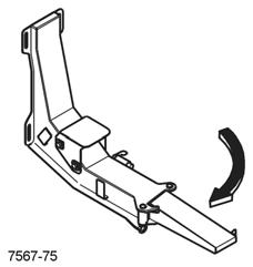
3. Using the jib pole, pull the front latch handle (1) (Figure4-61) down to put the latch pin in position to lock the extension against the main boom.
lugs (2). Insert the pins in the storage locations (3) and secure with the retaining clips.
Danger
Crushing Hazard!
Ensure the pins on the right side are properly installed and the extension is secured from swinging around before disconnecting the left side pins. Death or serious injury could occur.
4. Remove the retaining clips from the pins (1) (Figure4-62) securing the extension to the left side of the boom nose and remove the pins from the connecting
5. Disconnect the tag line from the boom nose and pull the front of the extension around so it rides up onto the runup ramp (2) (Figure4-60) and the locking lug (3) (Figure4-61) is fully engaged by front latch pin (2).
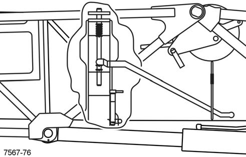
Danger
If the front latch pin (2) (Figure4-61) does not engage the 36 ft (11 m) extension, STOP. DO NOT continue to stow the boom extensions until the front latch pin has properly engaged the extension and the horizontal locking pin (1) (Figure4-63) has been installed correctly.
DO NOT climb onto decking or walk under boom extensions.
Severe injury or death may occur if the front latching mechanism is not properly attached to the boom extensions; the boom extensions may fall or swing away from the main boom stowage brackets.
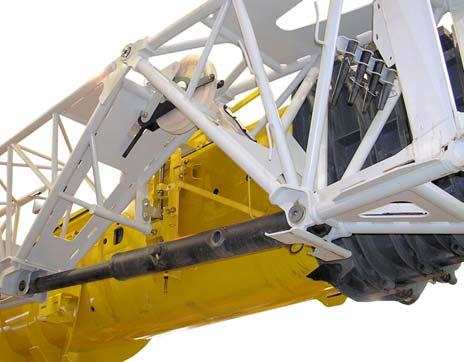
Contact Manitowoc Crane Care for correct adjustments if unable to align the extension with the spring pin or the locking pin.
6. Remove horizontal locking pin (1) (Figure4-63) from storage lugs and insert into the latch assembly, as shown, to lock the extension to the main boom. Secure horizontal locking pin with retaining clip.
10. Insert the pin (3) through the lugs on the main boom and the 23 ft (7 m) extension and secure with the retaining clip (4).
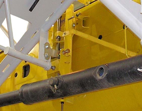
7. Remove the retaining clips from the pins (1) (Figure4-64) on the right side of the boom nose.
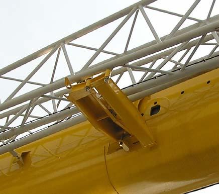
8. Remove the pins (1) from the attachment lugs (2) and insert them into the storage locations, secure the pins with the retaining clips.
9. Guide the tag line (1) around the end of the extension and through the bracket (2) (Figure4-65) on the main boom and back again. If possible, have a helper hold the tag line tight.
11. Pull the locking pin (1) (Figure4-66) down against spring force, and out of the attachment lug (2). Fold in the runup ramp (3) around until it can be secured with the spring latch (4).
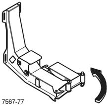
12. Remove all tag lines.
13. Reeve the hoist cable, refer to Cable Reeving, page 4-4
Boom Extension Transport Condition
The crane can be transported with the swingaway boom extension installed and secured at the side of the main boom or with the boom extensions completely removed. For transportation, with the boom extension installed, certain connections between both parts of the extensions must be established.
Warning
Crushing Hazard!
Always put the extension into transport condition when folded at the side or working with the main boom; only then is the extension safely secured.
An unsecured boom extension can fall resulting in death, serious injury or damaged equipment.
Check transport condition:
• After stowing the extension, before driving the crane with the extension folded at the side or when working with the main boom.
• Before erecting the swingaway boom extension.
Transport Condition with Extensions Installed
The transport condition with the extension folded at the side is created when all of the connections described in Stowing Procedure: 59 ft (18 m) Extension, page 4-41 are established. Check the following connections and establish them, if necessary:

With the 59 ft (18 m) Extensions Folded at the Side
• The 36 ft (11 m) extension is locked at the front support on the main boom and secured with the horizontal pin (Figure4-63).
• The two extensions are connected and secured with retaining pins (Figure4-59).
• The connection between 23 ft (7 m) extension and main boom at the rear, is secure (Figure4-65).
With the 23 ft (7 m) Extension Only Folded at the Side
• The connection between the extension and main boom is secured with retaining pins (Figure4-59).
• The connection between 23 ft (7 m) extension and main boom at the rear, is established (Figure4-67).
Installing and Removing the 26 ft (8 m) and 19 ft (6 m) Extension Inserts
Installation
1. Use another crane or suitable lifting device to install the extension.
2. Connect a sling to the two lifting lugs (1) (Figure4-68).
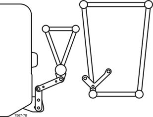
3. Lift the extension in front of the main boom head so the four connecting points (1) (Figure4-69) align on both sides.
4. Remove the pins from the holders.
5. Insert the pins into the connecting points (1) and secure them with retaining clips.
Removal
Caution
Equipment Damage Hazard!
Before removing an extension, ensure that the electrical and hydraulic connections have been disconnected and properly stowed to prevent damaging the cable and hydraulic hoses.
1. Use another crane or suitable lifting device to remove the extension.
2. Connect a sling to the two lifting lugs (1) (Figure4-68) and lift the extension enough to take the load off the connecting pins.
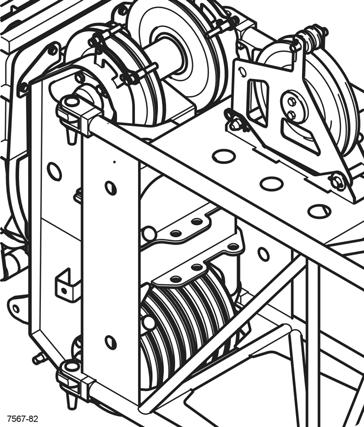
3. Verify the electrical and hydraulic connections have been disconnected. Refer to Extension Hydraulic Connection, page 4-47 and Extension Electrical Connection, page 4-46
4. Remove the pins from the connecting points (1) (Figure4-69).
5. Insert the pins into the holders and secure them with retaining clips.
6. Remove the extension.
The electric cable (1) (Figure4-70) is installed in the 26 ft (8 m) extension (2), with the long end of the cable wound on the stowage lugs (3).
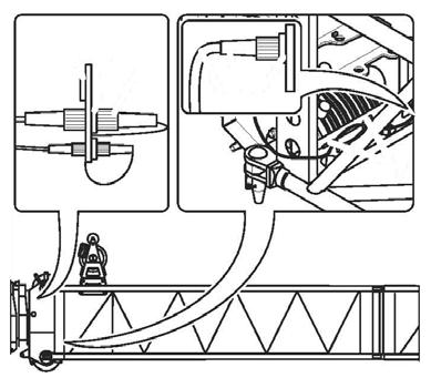
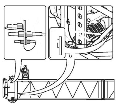
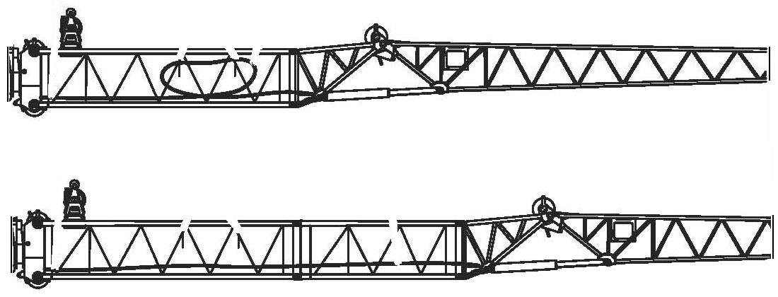
When the 105 ft (32 m) boom extension is rigged, the cable is routed through the 20 ft (6 m) extension (4).
Connecting Main Boom to the 26 ft (8 m) Extension
Establishing a Connection
1. Remove the bridging plug (1) (Figure4-71) from the socket (3) and plug it into the dummy socket (2).
2. Unwind the cable (5) from the holder (7).
3. Remove plug (4) from the dummy socket (6) and plug into the socket (3).
4. Wind up the cable (5) far enough on the holder (7) so that it will not be damaged during operation.
Disconnecting Main Boom Electrical Connection
1. Remove the plug (4) (Figure4-72) from the socket (3) and plug into the dummy socket (6).
2. Wind the cable (5) onto the holder (7).
3. Remove the plug (2) from the dummy socket (1) and plug it into the socket (3).
Connecting the Folding Extension Electrical Circuit
1. Unwind the cable (2) (Figure4-73) from the holder (1).
2. Remove the cap (4) off the socket (3).
3. Unwind the cable (6) from the holder (8).
4. Remove the bridging plug (5) from the dummy socket (7) and plug it into the socket (3).
5. Wind up the cable (8) far enough on the holder (7) so it will not be damaged during operation.
6. Wind up the cable (2) far enough on the holder (1) so it will not be damaged during operation.
Disconnecting the Folding Extension Electrical Circuit
1. Remove the bridging plug (5) (Figure4-74) from the socket (3) and plug it into the dummy socket (7).
2. WInd the cable (6) on to the holder (8).
3. Install the protective cap on the socket (3).
4. Wind the cable (2) onto the holder (1).
Extension Hydraulic Connection
All hydraulic lines are located in the 26 ft (8 m) extension (Figure4-75). The hose lines are installed so that short ends are located to the rear and long ends to the front of the extension.
The long ends (1) of the hoses are suspended from clamps. The short ends (2) of the hoses are positioned at the rear of the lower cross-strut.
NOTE: Connecting the hydraulic lines from the boom nose to the hydraulic luffing jib through the 26 ft (8 m) and 20 ft (6 m) extensions are the same as connecting to the 26 ft (8 m) extension only.
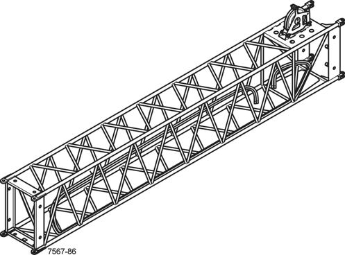
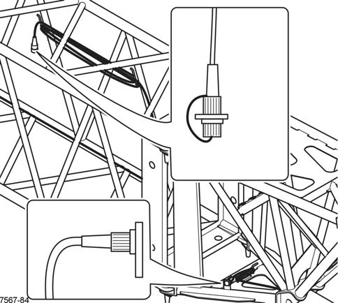
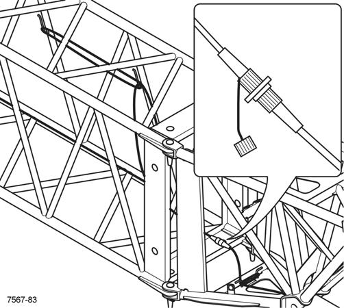
Connecting Main Boom Hydraulics
1. If necessary, install the hydraulic hoses (1) (Figure4-76) on the boom nose, refer to Extension Hydraulic Connections (Optional Hydraulic Extension), page 4-34.
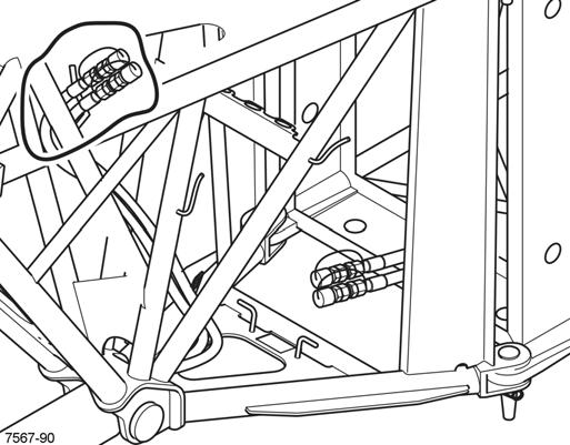
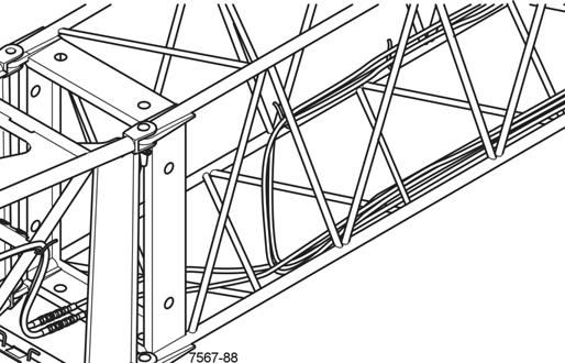
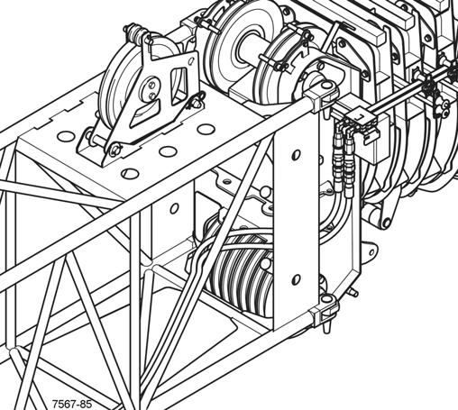
2. Route the short ends (2) to the main boom head.
3. Remove the protective caps and connect the short ends (2) to the boom nose connectors (1).
4. Secure the hoses (1) (Figure4-77) to the holders (2) to ensure the hoses are not damaged during operation.
Disconnecting the Folding Extension Hydraulics
1. Disconnect the hoses (3) from the long hose ends (4) (Figure4-79).
2. Install protective caps (1) (Figure4-78) on the hose ends.
Disconnecting Main Boom Hydraulics
1. Disconnect the short hose ends (2) from the boom nose connectors (1) (Figure4-76).
2. Cover the short end and boom nose connectors with the protective caps.
3. Route the short ends (2) inside and place them in front of the lower cross-strut so that they do not hang down.
Connecting the Folding Extension Hydraulics
1. Remove the long hose (1) (Figure4-77) from the holders (2) on the extension.
2. Route the hoses to the front of the extension.
3. Remove the protective caps and connect the folding extensions hoses (3) to the long hose ends (4).
3. Secure the hoses (2) to the holder (3) in the 36 ft (11 m) section.
4. Stow the long hoses (1) (Figure4-77) on the holders (2) provided.
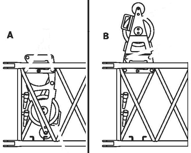
Folding Out the Deflection Sheave
1. Remove the retaining clips from the pins (3) (Figure4-80).
2. Hold the deflection sheave by the handle (1) and pull out the pins (3).
3. Fold the deflection sheave up by the handle (1) and insert the pins (3).
4. Secure the pins using the retaining clips.
Folding In the Deflection Sheave
5. Disconnect the short end hoses (1) (Figure4-79) from the 26 ft (8 m) extension from the boom nose connectors (2).
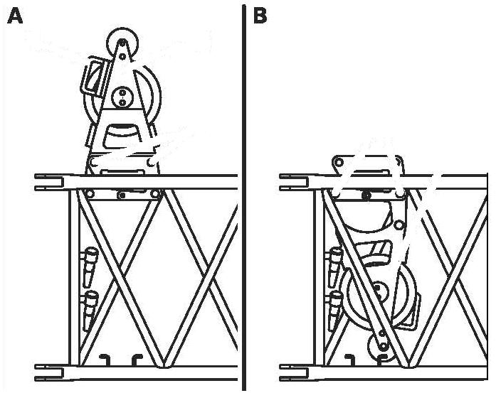
6. Install protective caps on the hose ends.
Folding the Deflection Sheave on the 26 ft (8 m)
Extension
NOTE: For folding and unfolding the deflection sheaves on the 36 ft section refer to Folding Deflection Sheaves, page 4-36
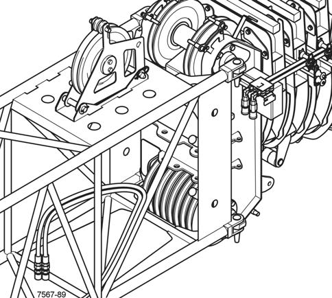
1. Remove the retaining clips from the pins (3) (Figure4-81).
2. Hold the deflection sheave by the handle (1) and pull out the pins (3).
3. Fold the deflection sheave (2) downwards and fasten it in this position with the pins (3).
4. Secure the pins (3) using retaining clips.
Positioning/Removing the Hoist Cable
Caution
Falling Objects Hazard!
Always secure the cable holding sheaves and pins with retaining clips. This prevents them from coming loose, falling down and causing injury.
Positioning the Cable
1. Remove the guide sheaves (1) (Figure4-82). Guide the cable over the deflection sheaves (2), (3), (4) and over the head sheave (5) on the 36 ft extension.

2. Replace all guide sheaves (1) and secure them with retaining clips.
3. Install the hook tackle or the hookblock. The cable can only be reeved once on the boom extension.
Removing the Cable
1. Unreeve the hookblock.
2. Remove the guide sheaves (1) (Figure4-82).
3. Take the cable off the head sheave (5) and the deflection sheaves (4), (3), (2) and place it onto the ground on the left side.
4. Replace all guide sheaves (1) and secure them with retaining clips.
AUXILIARY SINGLE-SHEAVE BOOM NOSE
The auxiliary boom nose (rooster sheave) is designed for the crane it was delivered with. It has the same serial number as the crane.
To use the auxiliary boom nose on several Grove cranes, it needs to be adapted to the corresponding crane and marked with all the serial numbers.
The serial number (1) (Figure4-83) is on the front of the auxiliary boom nose.
Caution
Incompatible Equipment Hazard!
Operate the crane only with the auxiliary boom nose that has the identical serial number as the crane.
The RCL is set only for the corresponding auxiliary boom nose.
The auxiliary boom nose should only be adjusted by an authorized Grove dealer or Manitowoc Crane Care. Injury or equipment damage may result if an incompatible boom nose is used.
Installation
1. Remove the pivot pin (1) (Figure4-84) from the boom nose.
2. Attach a sling to the lifting lug (2) on the boom nose.
3. Use another crane or suitable lifting device to lift the auxiliary boom nose in front of the boom head.
4. Align the boom nose with the mounting lugs (3) on the boom head and install the swivel pin (1), secure the pin with a retaining clip.
5. Place the auxiliary boom nose into either the Transport Position, page 4-52 or Working Position, page 4-52
Removal
1. Attach a sling to the lifting lug (2) (Figure4-84) on the boom nose.
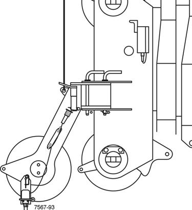
2. Use another crane or suitable lifting device to support the auxiliary boom nose while removing the mounting pins.
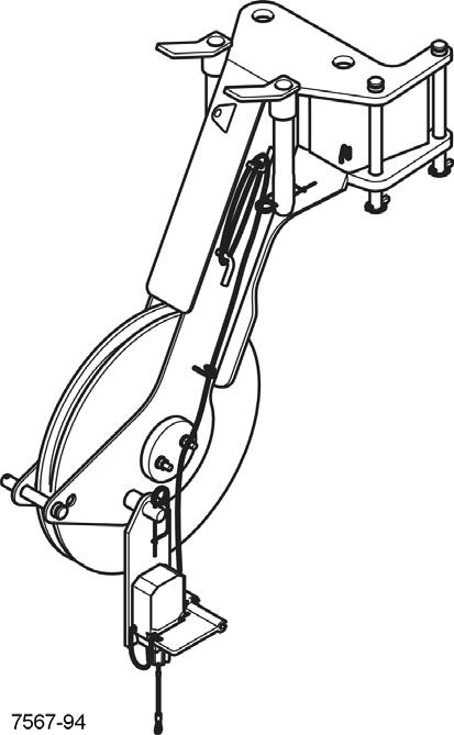
3. Remove all the pins securing the boom nose to the boom head (Figure4-83).
4. Lift the auxiliary boom nose from the head of the main boom.
5. Insert the pins into the lugs on the boom nose and secure with retaining clips.
Working Position
1. Verify the swivel pin (1) (Figure4-85) is installed.
2. If necessary, remove the pin (2) from the transport lug.
Rigging the auxiliary boom nose
3. Swing the auxiliary boom nose in front of the main boom head.
4. Remove the pins from the storage lugs (3).
5. Insert the pins into the mounting lugs (4) and secure with retaining clips.
6. Insert the pin (2) into the transport position lug and secure with retaining clip.
1. Remove the cable retaining pins (1) (Figure4-85) from the head of the main boom and from the auxiliary singlesheave boom nose.
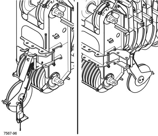
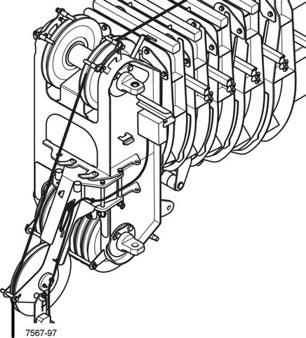
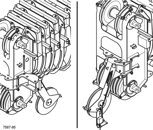
2. When reeving, guide the hoist rope over the left head sheave of the main boom, as shown.
3. Insert the cable retaining pins into the mounting lugs and secure them with the retaining clips.
4. Fasten the cable end clamp on the hook tackle or the hookblock.
Transport Position
1. Verify the swivel pin (1) (Figure4-87) is installed and secured with a retaining clip.
2. Remove the mounting pins from the mounting lugs (2).
3. Insert the mounting pins into the storage holes (3) and secure them with retaining clips.
4. Remove the transport pin (4).
5. Swing the auxiliary boom nose onto the side of the main boom.
6. Insert the transport pin in the transport lug (5) and secure it with a clip.
Heavy Duty Luffing Boom Extension
The heavy duty boom extension (Figure4-88) consists of three sections:
• a 12 ft (3.6 m) heavy duty section with luffing cylinder and fold down sheave
• a removable 24 ft (7.3 m) lattice section
• a fold-out 23 ft (7 m) stinger or fly section.
The heavy duty boom extension is designed for the crane it was delivered with. Each section has the same serial number as the crane.
Installation and Removal
Installation and removal of this extension is the same for the standard luffing extension, refer to Installing the Folding Boom Extension, page 4-25
The two lattice extensions are removed from the 12 ft section using a suitable lifting device to remove the load from the four attachment lugs and removing the attachment pins.
Heavy Duty Nose Sheave
Work Position
1. Remove the retaining clip (1) (Figure4-89) and then the pin (2).
2. Rotate the sheave into the work position.
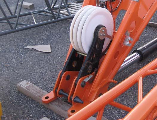
3. Secure the sheave assembly with the pin and retaining clip.
Stowed Position
1. Remove the retaining clip and then the pin.
2. Rotate the sheave up into the stowed position, as shown (Figure4-89).
3. Stow the pin (1) and secure with the retaining clip (2).
ANEMOMETER/AIRCRAFT WARNING LIGHT
Caution
Equipment Damage Hazard!
Always remove the anemometer/aircraft warning light before transporting the crane. This prevents damage by overhead obstructions and the anemometer from being damaged due to excessive air speeds.
Mounting Anemometer/Aircraft Warning Light
1. Insert the mounting arm (1) (Figure4-90) into the holder (3) and secure it with the retaining clips.
2. Remove the cable from the clamps (2); connect the anemometer cable to the socket (4), connect the aircraft warning light cable to the socket (5).
3. Arrange the cable so that it will not be damaged during crane operation.
4. Check that the anemometer is able to swing free so that it hangs vertically at different boom angles.
Removing Anemometer/Aircraft Warning Light
1. Take the plugs out of the sockets (4 and 5) (Figure4-90) and install the protective caps.
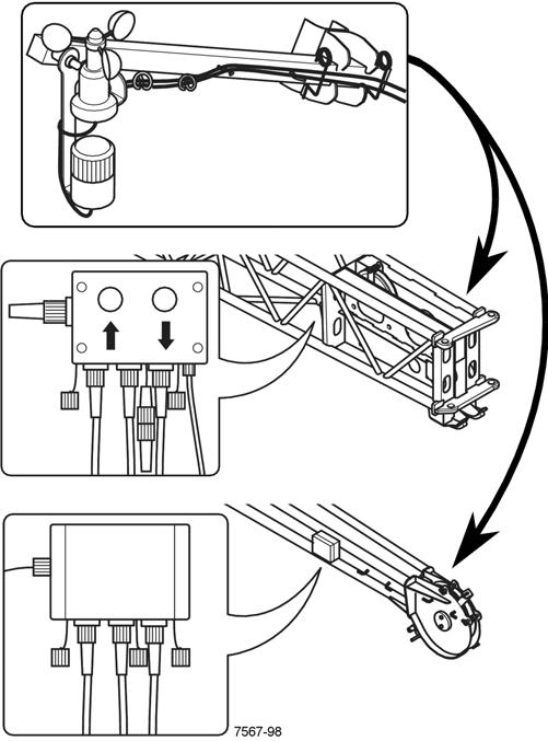
2. Wind the cable onto the clamps (2).
3. Remove the mounting arm (1) from the holder (3).
4. For transportation, fasten the retaining clips to the mounting arm (1).