29 minute read
RT9150E OPERATOR MANUALINTRODUCTION


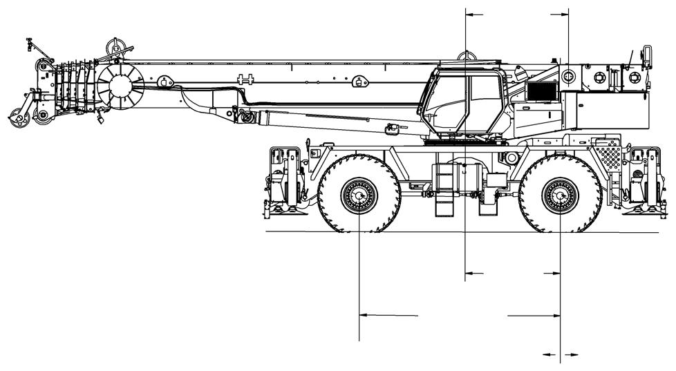
Table 1-1: Axle Weight Distribution Table
WIRE ROPE (HOIST CABLE) General
The following information is a compendium of information from various wire rope manufacturers and includes inspection, replacement, and maintenance guidelines for wire rope as established by ANSI/ASME B30.5, federal regulations, and Manitowoc. The inspection interval shall be determined by a qualified person and shall be based on such factors as expected rope life as determined by experience on the particular installation or similar installations, severity of environment, percentage of capacity lifts, frequency rates of operation, and exposure to shock loads. Periodic Inspections need not be at equal calendar intervals and should be performed at shorter time intervals as the wire rope approaches the end of its useful life. A periodic inspection shall be performed at least once a year. The following provides inspection and maintenance procedures for wire ropes used on Grove products (e.g. wire rope used as load lines [hoisting cables], boom extension and retraction cables, pendant cables, tow winch cables, and hook block tie down cables).
Environmental Conditions
The life expectancy of wire rope may vary due to the degree of environmental hostility and other conditions to which these mechanical devices are subjected. Variation in temperature, continuous excessive moisture levels, exposure to corrosive chemicals or vapors or subjecting the wire rope to abrasive material may shorten normal wire rope life. Frequent/ periodic inspections and maintenance of your wire rope is recommended for preventing premature wear and to insure long-term satisfactory performance.
Dynamic Shock Loads
Subjecting wire rope to abnormal loads beyond the endurance limit will shorten the wire ropes life expectancy. Examples of this type of loading are listed below.
1. High velocity movement e.g.; hoisting or swinging of a load followed by abrupt stops.
2. Suspending loads while traveling over irregular surfaces such as railroad tracks, potholes, and rough terrain.
3. Moving a load that is beyond the rated capacity of the lifting mechanism, i.e.; overloading.
Lubrication
A wire rope cannot be lubricated sufficiently during manufacture to last it’s entire life. Therefore, new lubricant must be added throughout the life of a rope to replace factory lubricant which is used or lost. It is important that lubricant applied as part of a maintenance program shall be compatible with the original lubricant, and to this end, the rope manufacturer should be consulted. Lubricant applied shall be of the type which does not hinder visual inspection. Those sections of rope which are located over sheaves or otherwise hidden during inspection and maintenance procedures require special attention when lubricating rope. The object of rope lubrication is to reduce internal friction and to prevent corrosion.
During fabrication, ropes receive lubrication; the kind and amount depends on the rope’s size, type, and anticipated use. This in-process treatment will provide the finished rope with ample protection for a reasonable time if it is stored under proper conditions. But, when the rope is put into service, the initial lubrication may be less than needed for the full useful life of the rope. Because of this possibility, periodic applications of a suitable rope lubricant are necessary.
The following are important characteristics of a good wire rope lubricant:
1. It should be free from acids and alkalis.
2. It should have sufficient adhesive strength to remain on the ropes.
3. It should be of a viscosity capable of penetrating the interstices between wires and strands.
4. It should not be soluble in the medium surrounding it under the actual operating conditions (i.e. water).
5. It should have a high film strength.
6. It should resist oxidation.
Before applying lubrication, accumulations of dirt or other abrasive material should be removed from the rope. Cleaning can be accomplished by using a stiff wire brush and solvent, compressed air, or live steam. Immediately after the wire rope is cleaned, it should be lubricated. Many techniques may be used; these include bath, dripping, pouring, swabbing, painting or pressure spray methods. Whenever possible, the lubricant should be applied at the top of a bend in the rope, because at that point the strands are spread by bending and are more easily penetrated. There should be no load on the rope while it is being lubricated. It should be noted, the service life of wire rope will be directly proportional to the effectiveness of the method used and amount of lubricant reaching the working parts of the rope.
Precautions and Recommendations During Inspection or Replacement
1. Always lock out equipment power when removing or installing wire rope assemblies.
2. Always use safety glasses for eye protection.
3. Wear protective clothing, gloves, and safety shoes as appropriate.
4. Use supports and clamps to prevent uncontrolled movement of wire rope, parts, and equipment.
5. When replacing fixed length cable assemblies (e.g. pendants) having permanently attached end fittings use only pre-assembled lengths of wire rope as supplied from Manitowoc. Do not build lengths from individual components.
6. Replace an entire wire rope assembly. Do not attempt to rework damaged wire rope or wire rope ends.
7. Never electroplate wire rope assemblies.
8. Do not weld any wire rope assembly or component unless welding is recommended by the wire rope manufacturer. Welding spatter shall never be allowed to come in contact with the wire rope or wire rope ends. In addition, be sure that the wire rope is not an electrical path during other welding operations.
9. Wire ropes are manufactured from special steels. If heating a wire rope assembly is absolutely necessary for removal, the entire wire rope assembly shall be discarded.
10. On systems equipped with two or more wire rope assemblies operating as a matched set, they shall be replaced as an entire set.
11. Do not paint or coat wire ropes with any substance except approved lubricants.
12. Measure the rope’s diameter across crowns (1) of the strands when determining if rope has become damaged (Figure1-4).
frequency of lifts, and exposure to shock loads. The inspection time intervals may also be predetermined by state and local regulatory agencies.
NOTE: Wire rope may be purchased through Manitowoc Crane Care.
Any deterioration observed in the wire rope should be noted in the equipment inspection log and an assessment concerning wire rope replacement should be made by a qualified person.
Keeping Records
A signed and dated report of the wire rope’s condition at each periodic inspection must be kept on file at all times. The report must cover all inspection points listed in this section. The information in the records can then be used to establish data which can be used to determine when a wire rope should be replaced.
It is recommended that the wire rope inspection program include reports on the examination of wire rope removed from service. This information can be used to establish a relationship between visual inspection and the rope’s actual internal condition at the time of removal from service.
Frequent Inspection
A frequent daily visual inspection is recommended for all running ropes in service. This inspection should be made on all wire rope which can be expected to be in use during the day’s operation. This inspection should be used to monitor progressive degradation and to discover severe damages necessitating wire rope replacement such as:
• Distortion, kinking, crushing, un-stranding, bird caging, reduction of diameter, etc.
• General corrosion.
• Broken or cut strands.
• Number, distribution and type of broken wires.
• Evidence of core failure.
• End fitting wear/abrasion.
FIGURE1-4
Wire Rope Inspection (Running Ropes and Pendant Cables)
Wire rope should be inspected frequently/daily and periodically/yearly in accordance with the following information excerpted from a National Consensus Standard as referenced by Federal Government Agencies. Recommended inspection intervals may vary from crane to crane and may vary based on environmental conditions,
Pay particular attention to areas of the rope where wear and other damage is likely to occur:
- Pick-up Points: Sections of wire rope that are repeatedly stressed during each lift, such as those sections in contact with sheaves.
- End Attachments: The point where a fitting is attached to the wire rope or the point where the wire rope is attached to the drum.
- Abuse Points: The point where the wire rope is subjected to abnormal scuffing and scraping.
Periodic Inspection
Wire rope should be inspected periodically/annually or at a shorter time interval if necessitated by environmental or other adverse conditions, and shall cover the entire length of the wire rope. Only the outer surface of the wire rope need be inspected, and no attempt should be made to open the rope. Periodic inspection should include all items listed under frequent inspection plus the following:
1. Inspect for reduction of rope diameter below nominal diameter.
2. Inspect for severely corroded or broken wires at end connections.
3. Inspect for severely corroded, cracked, bent, worn, or improperly applied end connections.
4. Inspect wire rope in areas subjected to rapid deterioration such as:
• Sections in contact with saddles, equalizer sheaves, or other sheaves where wire rope travel is limited.
• Sections of wire rope at or near terminal ends where corroded or broken wires may protrude.
5. Inspect boom nose sheaves, hook block sheaves, boom extension/jib sheaves, auxiliary boom nose sheaves, and hoist drums for wear. Damaged sheaves or hoist drums can accelerate wear and cause rapid deterioration of the wire rope.
Wire Rope Inspection/Replacement (All Wire Rope)
No precise rules can be given for determination of the exact time for replacement of wire rope since many variable factors are involved. Determination regarding continued use or replacement of wire rope depends largely upon the good judgement of an appointed and qualified person who evaluates the remaining strength in a used rope after allowance for any deterioration disclosed by inspection.
Wire rope replacement should be determined by the following information excerpted from a National Consensus Standard as referenced by Federal Government Agencies and as recommended by Ma nitowoc. All wire rope will eventually deteriorate to a point where it is no longer usable. Wire rope shall be taken out of service when any of the following conditions exist:
• Kinking, crushing, birdcaging, or any other damage resulting in distortion of the rope structure.
• Evidence of any heat damage from any cause.
• Reductions from nominal diameter of more than 5%.
• In running ropes, six randomly distributed broken wires in one lay or three broken wires in one strand in one lay.
• In standing ropes, more than two broken wires in one lay in sections beyond end connections or more than one broken wire at an end connection.
• In rotation resistant rope, two randomly distributed broken wires in six rope diameters or four randomly distributed broken wires in 30 rope diameters.
• Severe corrosion as evidenced by pitting.
• Manitowoc recommends that for cable extended booms, a single damaged wire rope assembly shall require replacement of the entire set of extension cables.
• Manitowoc recommends for cable extended booms, that boom extension cables be replaced every seven (7) years.
Seizing Wire Rope
It is important to seize the ends of rotation resistant wire ropes to prevent the displacement and unraveling of the individual wires and strands at the ends. All preformed and non-preformed styles of wire rope should be seized prior to cutting. Seizings must be placed on both sides of the point where the wire rope is to be cut.
The two preferred methods for seizing wire ropes are:
Method 1
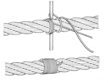
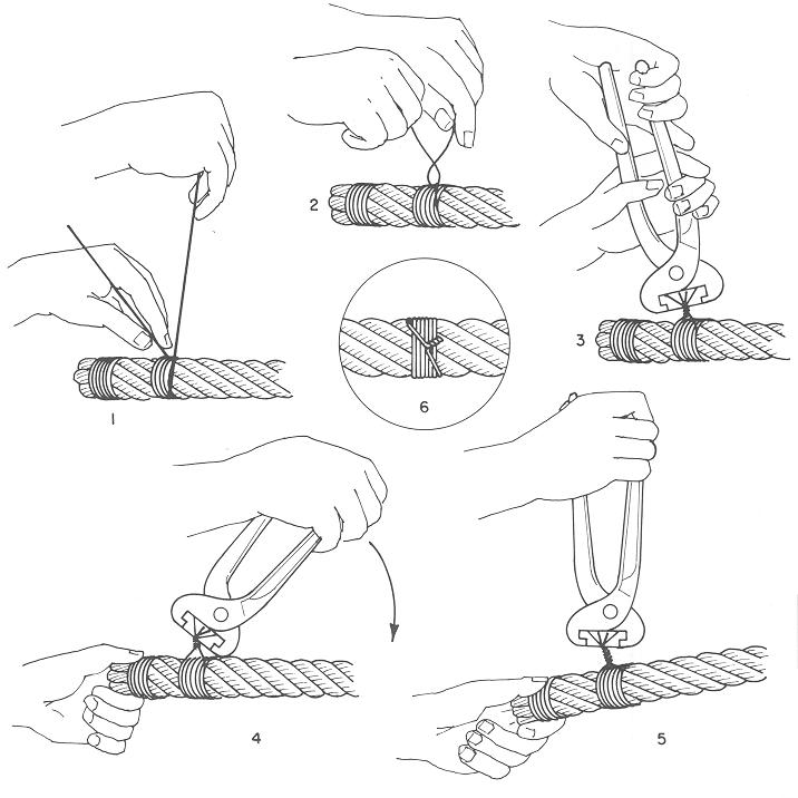
Using a length of soft annealed wire (Figure1-5), place one end in the groove between two strands of the wire rope. Turn the long end of the annealed wire at right angles to the wire and wrap it tightly over the portion in the groove.
The two ends of the annealed wire should be twisted together tightly. Cut off the excess wire and pound the twist flat against the wire rope.
Wind a length of soft annealed wire (Figure1-6) around the wire rope at least seven times. The two ends should be twisted together in the center of the seizing. Tighten the seizing by alternately prying and twisting. Cut off both ends of the wire and pound the twist flat against the rope.
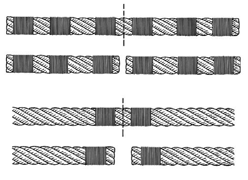
NOTE: Non-preformed wire rope (1) (Figure1-7) should have three seizings (3) located on each side of the cut (4) as compared to preformed wire rope (2).
Installing 35x7 Class Wire Rope
Caution
Any cutting of this specific wire rope is not recommended. If 35x7class wire rope must be cut for any reason, it is necessary to follow the following instructions. Also, unlike other types of wire rope, the ends on this wire rope must be welded to retain the rotation resistant characteristics.
1. Unload properly and relieve any twists. Pull the rope off the shipping reel or unroll it from a shipping coil. (If done improperly, you may kink the rope, which will result in permanent damage to the rope.) Then, lay the rope on the ground in direct line with the boom. This helps release any twist in the rope.
2. Pull the rope over the point sheave and attach the end to the hoist drum. Be sure not to remove the welded end.
3. Wind rope onto drum slowly and carefully. At this point, it isn’t necessary to provide additional load other than the weight of the rope being pulled across the ground.
4. Spool first layer tightly. It is essential on smooth-faced drums that the first layer is spooled with wraps tight and close together since the first layer forms the foundation for succeeding layers. If need be, use a rubber, lead or brass mallet (but never a steel hammer) to tap the rope into place.
5. Spool multiple layers with sufficient tension. It’s very important to apply a tensioning load to the ropes during the rope breaking-in process. (If not, the lower layers may be loose enough that the upper layers become wedged into the lower layers under load, which can seriously damage the rope.) The tensioning load should range from 1 to 2% of the rope’s minimum breaking force.
6. For ropes in multi-part systems: Reeve the traveling block and boom tip sheaves so the rope spacing is maximized and the traveling (hook) block hangs straight and level to help assure block stability.
7. Breaking in new 35x7 class rope—After installation, properly break in the rope, which allows the rope’s component parts to adjust themselves to the operating conditions:
With the boom fully raised and fully extended, attach a light load at the hook and raise it a few inches off the ground. Allow to stand for several minutes. Then cycle the load between the full “up” and “down” positions several times. Observe the drum winding and rope travel for any potential problems.
After making the lifts with a light load, increase the load and cycle it up and down a few times. This procedure will train the rope and help assure smooth operation during its useful life.
Ideally, you should run these loads with reeving that lets you place the loads on the block with all rope off the drum except the last three wraps. If this is not possible, alternate methods must be used to assure proper tensioning of the rope on the drum.
Published 2-18-2016, Control # 614-00 Grove
Section
SAFETY MESSAGES General
The importance of safe operation and maintenance cannot be overemphasized. Carelessness or neglect on the part of operators, job supervisors and planners, rigging personnel, and job site workers can result in their death or injury and costly damage to the crane and property.
To alert personnel to hazardous operating practices and maintenance procedures, safety messages are used throughout the manual. Each safety message contains a safety alert symbol and a signal word to identify the hazard’s degree of seriousness.
Safety Messages
General
The importance of safe operation and maintenance cannot be overemphasized. Carelessness or neglect on the part of operators, job supervisors and planners, rigging personnel, and job site workers can result in their death or injury and costly damage to the crane and property.
To alert personnel to hazardous operating practices and maintenance procedures, safety messages are used throughout the manual. Each safety message contains a safety alert symbol and a signal word to identify the hazard’s degree of seriousness.
Safety Alert Symbol
This safety alert symbol means ATTENTION! Become alert - your safety is involved! Obey all safety messages that follow this symbol to avoid possible death or injury.
Signal Words
Danger
Identifies hazards that will result in death or serious injury if the message is ignored.
Warning
Identifies hazards that may result in death or serious injury if the message is ignored
Caution
Identifies hazards that could result in minor or moderate injury if the message is ignored.
Caution
Without the safety alert symbol, identifies hazards that could result in property damage if the message is ignored.
NOTE: Emphasizes operation or maintenance procedures.
General
It is impossible to compile a list of safety precautions covering all situations. However, there are basic principles that must be followed during your daily routine. Safety is your primary responsibility, since any piece of equipment is only as safe as the person at the controls
Read and follow the information located in Model Specific Information near the end of this section.
This information has been provided to assist in promoting a safe working atmosphere for yourself and those around you. It is not meant to cover every conceivable circumstance which could arise. It is intended to present basic safety precautions that should be followed in daily operation.
Because you are the only part of the crane that can think and reason, your responsibility is not lessened by the addition of operational aids or warning devices. Indeed, you must guard against acquiring a false sense of security when using them. They are there to assist, not direct the operation. Operational aids or warning devices can be mechanical, electrical, electronic, or a combination thereof. They are subject to failure or misuse and should not be relied upon in place of good operating practices.
You are the only one who can be relied upon to assure the safety of yourself and those around you. Be a professional and follow the rules of safety
Remember, failure to follow just one safety precaution could cause an accident that results in death or serious injury to personnel or damage to equipment. You are responsible for the safety of yourself and those around you.
Warning Signs
Refer to the Parts Manual for a drawing indicating the location of warning signs on the crane.
Accidents
Following any accident or damage to equipment, the Manitowoc dealer must be immediately advised of the incident and consulted on necessary inspections and repairs. Should the dealer not be immediately available, contact should be made directly with Manitowoc Product Safety at the address below. The crane must not be returned to service until it is thoroughly inspected for any evidence of damage. All damaged parts must be repaired or replaced as authorized by your Manitowoc distributor and/or Manitowoc Crane Care.
If this crane becomes involved in a property damage and/or personal injury accident, immediately contact your Manitowoc distributor. If the distributor is unknown and/or cannot be reached, contact Product Safety at:
The Manitowoc Company, Inc.
1565 East Buchanan Trail
Shady Grove, PA 17256-0021
Phone:888-777-3378 (888-PSR.DEPT)
717-597-8121
Fax:717-593-5152
E-mail:product.safety@manitowoc.com
Operator Information
You must read and understand this Operator Manual and the Load Chart before operating your new crane. You must also view and understand the supplied safety video. This manual and Load Chart must be readily available to the operator at all times and must remain in the cab (if equipped) or operator’s station while the crane is in use.
The Operator Manual supplied with and considered part of your crane must be read and completely understood by each person responsible for assembly, disassembly, operation and maintenance of the crane.
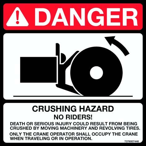
No personnel shall be allowed to climb onto the crane or enter the crane cab or operator’s station unless performance of their duties require them to do so, and then only with knowledge of the operator or other qualified person.
Allow No One other than the operator to be on the crane while the crane is operating or moving, unless they are seated in a two-man cab.
maintained crane. You risk lives when operating faulty machinery - including your own.
If adjustments or repairs are necessary, the operator shall notify the next operator.
Operator Qualifications
Qualified person is defined as one who by reason of knowledge, training and experience is thoroughly familiar with crane operations and the hazards involved. Such a person shall meet the operator qualifications specified in Occupational Safety and Health Administration (OSHA) Regulations (United States Federal Law), in ASME B30.5 American National Standard, or in any other applicable federal, state or local laws.
Ensure that all personnel working around the crane are thoroughly familiar with safe operating practices. You must be thoroughly familiar with the location and content of all placards and decals on the crane. Decals provide important instructions and warnings and must be read prior to any operational or maintenance function.
Refer to the Parts Manual for this crane for the locations of all safety decals.
You must be familiar with the regulations and standards governing cranes and their operation. Work practice requirements may vary slightly between government regulations, industry standards, and employer policies so a thorough knowledge of all such relevant work rules is necessary.
Do not remove the Load Chart , this Operator Manual , or any decal from this crane.
Inspect the crane every day (before the start of each shift). Ensure that routine maintenance and lubrication are being dutifully performed. Don’t operate a damaged or poorly
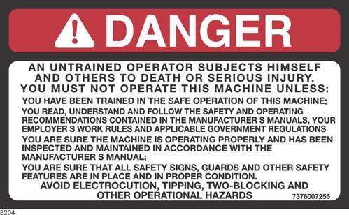
An untrained operator subjects himself and others to death or serious injury.
You must not operate this crane unless:
• You have been trained in the safe operation of this crane.
• You read, understand, and follow the safety and operating recommendations contained in the manufacturer’s manuals, your employer’s work rules, and applicable government regulations.
• You are sure the crane has been inspected and maintained in accordance with the manufacturer’s manuals and is operating properly.
• You are sure that all safety signs, guards, and other safety features are in place and in proper condition.
Do not attempt to operate the crane unless you are trained and thoroughly familiar with all operational functions. Controls and design may vary from crane to crane; therefore, it is important that you have specific training on the particular crane you will be operating.
Training is ESSENTIAL for pr oper crane operation. Never jeopardize your own well-being or that of others by attempting to operate a crane on which you have not been trained.
You must be mentally and physically fit to operate a crane. Never attempt to operate a crane while under the influence of medication, narcotics, or alcohol. Any type of drug could impair physical, visual and mental reactions, and capabilities.
As operator of this crane, you are granted the authority to stop and refuse to lift loads until safety is assured.
Operational Aids
Operational aids are accessories that provide information to facilitate operation of a crane or that take control of particular functions without action of the operator when a limiting condition is sensed, as stated in the latest revision of the ASME B30.5, and ASME B30.8 standards. Examples of such devices include, but are not limited to, the following: anti-two-block device, rated capacity indicator, rated capacity limiter, boom angle or radius indicator, boom length indicator, crane level indicator, hoist drum rotation indicator, load indicator, and wind speed indicator.
Manitowoc remains committed to providing reliable products that enable users and operators to safely lift and position loads. Manitowoc has been an industry leader in the incorporation of operational aids into the design of its cranes. Federal law requires that cranes be properly maintained and kept in good working condition. The manuals that Manitowoc provides that are specific for each crane and the manufacturer’s manuals for the operational aids shall be followed. If an operational aid should fail to work properly, the crane user or owner must assure that repair or recalibration is accomplished as soon as is reasonably possible. If immediate repair or recalibration of an operational aid is not possible and there are exceptional circumstances which justify continued short-term use of the crane when operational aids are inoperative or malfunctioning, the following requirements shall apply for continued use or shutdown of the crane:
• Steps shall be taken to schedule repairs and recalibration immediately. The operational aids shall be put back into service as soon as replacement parts, if required, are available and the repairs and recalibration can be carried out. Every reasonable effort must be made to expedite repairs and recalibration.
• When a Load Indicator, Rated Capacity Indicator, or Rated Capacity Limiter is inoperative or malfunctioning, the designated person responsible for supervising the lifting operations shall establish procedures for determining load weights and shall ascertain that the weight of the load does not exceed the crane ratings at the radius where the load is to be handled.
• When a Boom Angle or Radius Indicator is inoperative or malfunctioning, the radius or boom angle shall be determined by measurement.
• When an Anti-Two-Blocking Device, Two-Blocking Damage Prevention Device or Two-Block Warning Device is inoperative or malfunctioning, the designated person responsible for supervising the lifting operations shall establish procedures, such as assigning an additional signal person to furnish equivalent protection. This does not apply when lifting personnel in load-line supported personnel platforms. Personnel shall not be lifted when anti-two-block devices are not functioning properly.
• When a Boom Length Indicator is inoperative or malfunctioning, the designated person responsible for supervising the lifting operations shall establish the boom lengths at which the lift will be made by actual measurements or marking on the boom.
• When a Level Indicator is inoperative or malfunctioning, other means shall be used to level the crane.
Rated Capacity Limiter (RCL) Systems (If Equipped)
Your crane may be equipped with an RCL system which is intended to aid the operator. An RCL is a device that automatically monitors radius, load weight, and load rating and prevents movements of the crane, which would result in an overload condition.
Test daily for proper operation. Never interfere with the proper functioning of operational aids or warning devices.
Under no condition should it be relied upon to replace the use of Load Charts and operating instructions. Sole reliance upon these electronic aids in place of good operating practices can cause an accident.
Know the weight of all loads and always check the capacity of the crane as shown on the Load Chart before making any lifts.
NEVER exceed the rated capacity shown on the Load Chart
Always check the Load Chart to ensure the load to be lifted at the desired radius is within the rated capacity of the crane.
For detailed information concerning the operation and maintenance of the RCL system installed on the crane, see the RCL manufacturer’s manual supplied with the crane. Manufacturers of rated capacity limiters may refer to them in their manuals as a load moment indicator (LMI), a hydraulic capacity alert system (HCAS), a safe load indicator (SLI), or an EKS5; Manitowoc refers to these systems as a rated capacity limiter ( RCL) throughout its Operator and Service Manuals
Anti-Two-Blocking Device
This crane should have a functional Anti-Two-Block and Control Lock-Out System. Test daily for proper operation.
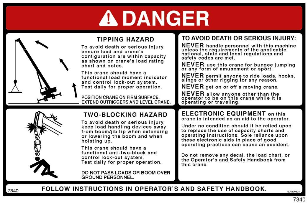
Two-blocking occurs when the load block (hook block, headache ball, rigging, etc.) comes into physical contact with the boom (boom nose, sheaves, jib, etc.). Two-blocking can cause hoist rope (wire rope or synthetic rope), rigging, reeving, and other components to become highly stressed and overloaded in which case the hoist rope may fail allowing the load, block, etc. to free fall.
Two-blocking is more likely to occur when both the main and auxiliary hoist lines are reeved over the main boom nose and jib nose respectively. An operator, concentrating on the specific line being used, may telescope or lower the boom allowing the other hoist line attachment to contact the boom or jib nose, thus causing damage to the sheaves, or causing the hoist rope to fail, dropping the lifting device to the ground and possibly injuring personnel working below.
Caution must be used when lowering the boom, extending the boom or hoisting up. Let out load line(s) simultaneously to prevent two-blocking the boom tip(s) and the hook block, etc. The closer the load is carried to the boom nose the more important it becomes to simultaneously let out hoist rope as the boom is lowered. Keep load handling devices a minimum of 107cm (42in) below the boom nose at all times.
Two-blocking can be prevented. Operator awareness of the hazards of two-blocking is the most important factor in preventing this condition. An Anti-Two-Block System is intended to assist the operator in preventing dangerous twoblock conditions. It is not a replacement for operator awareness and competence.
Never interfere with the proper functioning of operational aids or warning devices.
Working Area Limiter (If Equipped)
This crane may be equipped with a working area limiter as part of the RCL system, designated as either Work Area Definition System (WADS) or Working Range Limiter (WRL). You must read and understand the operator manual before operating the working area limiter system. Become familiar with all proper operating procedures and with the identification of symbol usage.
The working area limiter is intended to be used as an aid to the operator. It is not a substitute for safe crane operating practices, experience and good operator judgments.
CRANE STABILITY/STRUCTURAL STRENGTH
To avoid death or serious injury, ensure that the crane is on a firm surface with load and crane’s configuration within capacity as shown on the crane’s Load Chart and notes.
Ensure all pins and floats are properly installed and outrigger beams are properly extended before lifting on outriggers. On models equipped with outriggers that can be pinned at the mid-extend position (vertical stripe, if applicable), the outriggers must also be pinned when operating from the midextend position.
Use adequate cribbing under outrigger floats to distribute weight over a greater area. Check frequently for settling. Read and follow the following safety decal for cranes with center front stabilizers.
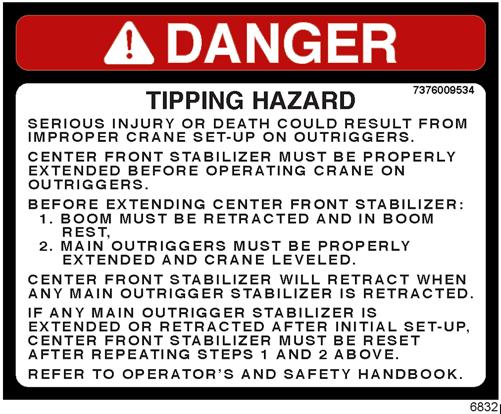
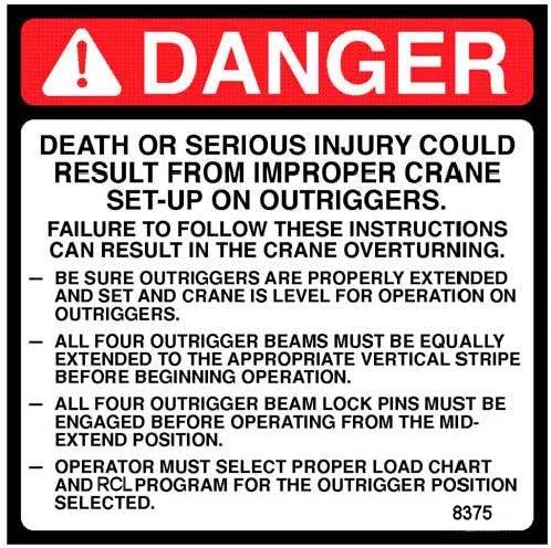
Carefully follow the procedures in this Operator Manual when extending or retracting the outriggers. Death or serious injury could result from improper crane setup on outriggers.
The operator must select the proper Load Chart and Rated Capacity Limiter (RCL) System program for the outrigger position selected.
Before swinging the superstructure over the side when the outriggers are retracted, check the Load Chart for backwards stability.
Long cantilever booms can create a tipping condition when in an extended and lowered position. Retract the boom proportionally with reference to the capacity of the applicable Load Chart.
Check crane stability before lifting loads. Ensure the outriggers (or tires if lifting on rubber) are firmly positioned on solid surfaces. Ensure the crane is level, brakes are set, and the load is properly rigged and attached to the hook. Check the Load Chart against the weight of the load. Lift the load slightly off the ground and recheck the stability before proceeding with the lift. Determine the weight of the load before you attempt the lift.
Unless lifting within On Rubber capacities, outrigger beams and jack cylinders (plus center front stabilizer, if equipped) must be properly extended and set to provide precise leveling of the crane. Tires must be clear of the ground before lifting on outriggers.
Actual loads, including necessary allowances, should be kept below the capacity shown on the applicable Load Chart
Load Chart capacities are based on freely suspended loads. You must use the appropriate Load Chart when determining the capability of the crane in the configuration required to perform the lift.
Maximum lifting capacity is available at the shortest radius, minimum boom length, and highest boom angle.
Do not remove the Load Charts from the crane.
Work Site
Prior to any operation, you must inspect the entire work site, including ground conditions, where the crane will travel and operate. Be sure that the surfaces will support a load greater than the crane’s weight and maximum capacity.
Be aware of all conditions that could adversely effect the stability of the crane.
Be aware of the danger for people entering the working area. Do not allow unnecessary personnel in the vicinity of the crane while operating.
Wind Forces
There are basic principles t hat must be followed while operating in windy conditions . This information has been provided to assist in determining safe operation in windy conditions.
Always use extreme caution when windy conditions exist. NEVER exceed the rated capacity shown on the Load Chart
Always check the Load Chart to ensure the load to be lifted is within the rated capacity of the crane.
Wind can have a significant effect on loads that may be lifted by a crane. Wind forces act differently on a crane depending upon the direction from which the wind is blowing (e.g., wind on the rear of the boom can result in decreased forward stability, wind on the underside of the boom can result in decreased backward stability, wind on the side of the boom can result in structural damages, etc.)
KEEP THE BOOM SHORT. Swinging loads with a long line can create an unstable condi tion and possible structural failure of the boom.
Load Charts
Load Charts represent the absolute maximum allowable loads, which are based on either tipping or structural limitations of the crane under specific conditions. Knowing the precise load radius, boom length, and boom angle should be a part of your routine planning and operation.
Wind forces can exert extreme dynamic loads. Manitowoc recommends that a lift not be made if the wind can cause a loss of control in handling the load.
Wind forces can be determined by typical visible effects on the landscape.To assist you in determining prevailing wind conditions, refer to Table 2-1.
NOTE: The wind speed corresponding to the Beaufort scale in the table is mean wind speed at 10m (33ft) elevation over a period of 10 minutes.
Smoke drift indicates wind direction. Leaves and wind vanes are stationary.
Wind felt on exposed skin. Leaves rustle. Wind vanes begin to move. 3
2Light Breeze3.311.97.4
5.419.412.1
Leaves and small twigs constantly moving. Light flags extended.
4
7.928.417.7Dust and loose paper raised. Small branches begin to move.
5
10.738.523.9
Branches of a moderate size move. Small trees in leaf begin to sway.
6
13.849.730.9
Large branches in motion. Whistling heard in overhead wires. Umbrella use becomes difficult. Empty plastic bins tip over.
7High Wind17.161.638.3Whole trees in motion. Effort needed to walk against the wind.
8Gale20.774.546.3
9Strong Gale24.487.854.6
Some twigs broken from trees. Cars veer on road. Progress on foot is seriously impeded.
Some branches break off trees, and some small trees blow over. Construction/temporary signs and barricades blow over.
10Storm28.4102.263.5Trees are broken off or uprooted, structural damage likely.
Wind Speeds
The maximum permissible wind speed referred to in the load charts is the 3-second wind gust speed measured at the boom tip height and is designated as V(z) . This value is either recorded at boom tip or calculated based on mean wind speed recorded at crane operation site. For lift planning purposes only, the 3-second wind gust speed, V(z), may be calculated based on mean wind speed reported at http:// www.windfinder.com “Super Forecast”.
This 3-second wind gust is assumed to act on the entire crane and the load. The wind effect on the load can be conservatively estimated as: a) If V(z) is ≤ 13.4m/s (30mph), then the allowable load is the published rated capacity from the Load Chart. b) If V(z) is >13.4m/s (30mph) and is ≤ 20.1m/s (45mph), the allowable load is the published rated capacity multiplied by the Capacity Reduction Factor from Table 2-4 (metric) or (non-metric). c) If V(z) is >20.1m/s (45mph), then lifting is NOT permitted. Cease lifting operations and lower and retract the boom.
NOTE: This condition is limited to operation with the main boom on fully extended outriggers only.
In both cases a) and b) above, the lift may also be limited by the projected wind area of the load Ap and by the wind drag coefficient Cd : This limit can be determined by comparing the Actual wind resistance area with the Allowable wind resistance area.
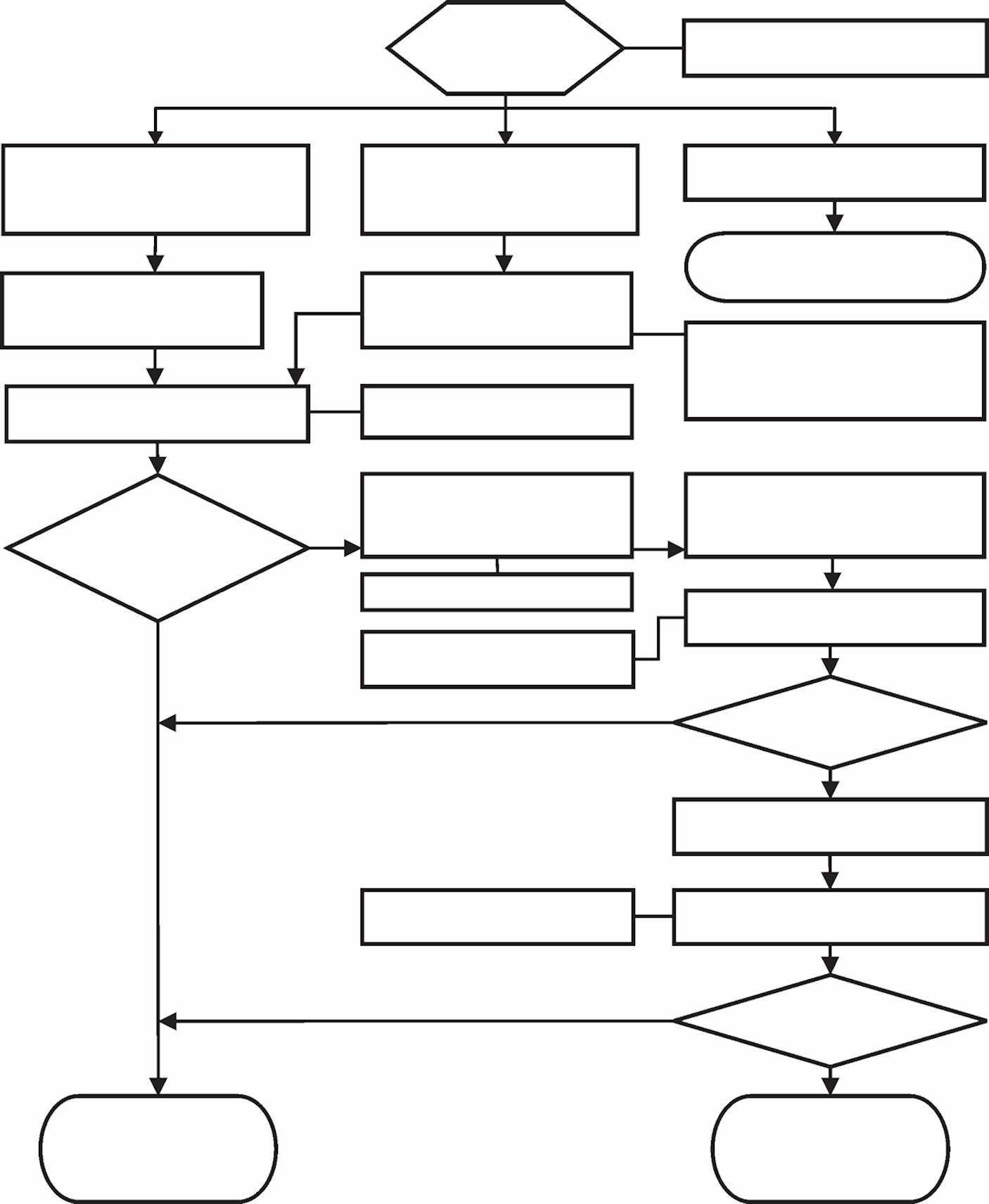
Refer to Figure2-2 for a simplified calculation method to determine permissible wind speed.
Simplified Method to Determine Maximum Permissible Wind Speed
Determination of 3-second wind gust speed at boom tip height:
The following example illustrates how to calculate 3-second wind gust speed at boom tip height based on mean wind speed recorded by the device located at the crane operation site:
V(z) is the 3-second wind gust speed at boom tip height Z then:
Metric, with Z [m] and V [m/s]
V(z) =[(Z/10)0.14 + 0.4] x V (2.1)
Non-metric, with Z [ft] and V [mph]
V(z) =[(Z/33)0.14 + 0.4] x V (2.2) where:
V [m/s] [mph] - Mean wind speed at 10m(22ft) elevation (upper limit of Beaufort scale)
Example : Suppose you want to lift the load with the maximum boom tip height of 30m (100ft) and the recorded mean wind speed by the device located at the crane operation site is 5.5m/s (13mph). This mean wind speed of 5.5m/s (13mph) corresponds to Beaufort number 4 (see Table 2-1). The maximum wind velocity according to the Beaufort scale of 4 is 7.9m/s (17.7mph).
The mean wind speed (upper limit of Beaufort number) at 10m (33ft) height, to be used for calculation is:
V =7.9m/s (17.7mph)
Boom tip height for this lift is Z = 30m (100ft) then:
Metric, with Z [m] and V [m/s]
V(z) =[(30/10)0.14 +0.4]x7.9= 12.4m/s
Non-metric, with Z [ft] and V [mph]
V(z) =[(100/33)0.14 +0.4]x17.7=27.8mph
Since V(z) is ≤ 13.4m/s (30mph), the allowable loads are the published rated capacities from the Load Chart and can be lifted at this condition.
Size and Shape of the load:
These rated capacities are also based on the assumption that the Wind Resistance Area of load, Awr(load) is not more than 0.0012square meters per kilogram (0.0059 sq.ft per pound of load. (See below Formulas 2.4 and 2.5.)
The load capacities shall be reduced to account for the larger wind resistance area of load and 3-second wind gust speed at boom tip height. Use tag lines when the wind gust speed is above 13.4 m/s (30mph) to help control the movement of the load. Manitowoc recommends that a lift not be made if the wind can cause a loss of control in handling the load.
The lift may also be limited by the projected wind area of the load Ap and by the wind drag coefficient Cd. This limit can be determined by comparing the actual wind resistance area of the load with the allowable wind resistance area.
Awr(load) = Ap x Cd (2.3) where:
Awr(load) [m2] [ft2] .- Wind resistant area of the load
Ap [m2] [ft2] - projected wind area, Cd - wind drag coefficient.
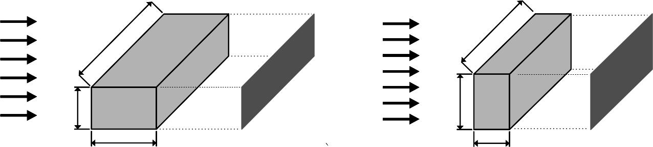
Ap is determined by using the calculation of maximum height x maximum length (see Figure2-3).
For Cd, refer to Table 2-2. If the Cd cannot be calculated or estimated, use a value of 2.4.
The allowable wind resistant area of the load Awr (allow) is equal to 0.0012 square meters per kilogram (0.0059 sq.ft per pound) of allowable load:
Metric, with m(load) [kg] - Mass of the allowable load
Awr(allow) =0.0012 × m(load) (2.4)
Non-metric, with m(load) [lb] - Mass of the allowable load
Awr(allow) =0.0059 × m(load) (2.5)
If Awr(load) is greater than Awr(allow), then lifting this load at this wind speed V(z) is NOT permitted.
Calculation of Projected Wind Area (Ap):
Determining Wind Drag Coefficient (Cd)
Table 2-2 shows the typical Shapes and corresponding Wind Drag Coefficient (Cd) values.
If the exact Wind Drag Coefficient of a shape is not known, use the maximum value of the shape’s range (Table 2-2).
If the wind drag coefficient of the load cannot be estimated or determined, it shall be assumed that (Cd)= 2.4
Table 2-2 Wind Drag Coefficient Maximum Permissible Wind Speed
If the wind resistant area of the load Awr(load) is greater than the allowable wind resistant area Awr(allow), the ratio can be used to determine a permissible wind speed V(z) for the load using Table 2-3.
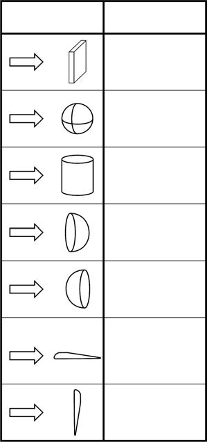
Table 2-3 Awr Ratio and Permissible Wind Speed V(z)-Non-metric
Note: Permissible and rated wind speeds in this table are the 3-second gust wind speeds at boom tip height.
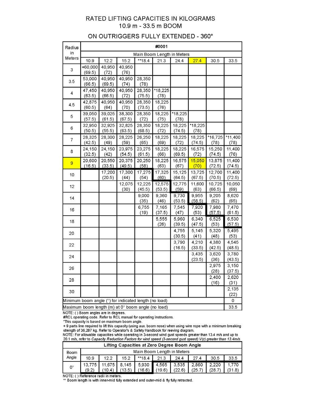
Table 2-4 Example-Capacity Reduction Factors for Wind Speed V(z) Greater than 13.4m/s - Metric
(Only for lifting with main boom on fully extended outriggers, with or without stowed extension)
For wind speed V(z) (3-second gust speed at boom tip height) V(z) >13.4m/s ≤ 20.1m/s, the Reduced Capacity shall be calculated by multiplying the Published Rated Capacity by the following factors:
Main Boom Length in Meters
Wind resistance area of load, Awr(load) shall not exceed maximum allowable wind resistance area Awr(allow).
Maximum allowable wind resistance area, [m2] Awr(allow) =0.0012 x calculated reduced capacity in kg.
Wind resistance area of load, Awr(load) = projected wind area Ap x wind drag coefficient Cd for the load. For wind resistance Area of load, Awr (load) > maximum allowable wind resistance area, Awr(allow) refer to crane Operator Manual.
Table 2-5 Awr Ratio and Permissible Wind Speed V(z) - Metric
Note: Permissible and rated wind speeds in this table are the 3-second gust wind speeds at boom tip height.
Example and Sample Calculations (metric)
The following example illustrates how to calculate allowable load while operating in wind speed (3-second wind gust speed) above 13.4m/s (30mph) and maximum permissible wind speeds with various combinations of lifted load and wind resistance area.
NOTE: Permissible and calculated wind speeds in this example are the 3-second wind gust speeds at boom tip height V(z).
Example 1: Crane Configuration:
• boom length = 27.4m,
• load radius = 9m,
• wind speed is measured at V(z) ≤ 20.1m/s.
From the Rated Load Chart Example-Metric (Figure2-3), at maximum permissible wind speed, V(z) = 13.4m/s, the rated lifting capacity m (allow) for this configuration is 15,050kg.
The maximum allowable wind resistance area of load is
Awr(allow) =0.0012 x m(load) (2.4)
Awr(allow) =0.0012 x15,050 = 18.06m2
Lifting Limits at wind speed V(z) ≤ 13.4m/s at this configuration:
• Maximum load 15,050kg
• Maximum wind resistance area of load 18.06m2
For the allowable wind speed >13.4m/s and ≤ 20.1m/s, reduce the allowable load. Per Table 2-4, the Factor for main boom length of 27.4m is 0.8, the allowable load is: m(allow) =0.8 x15,050 = 12,040kg
This reduced capacity load has an allowable wind resistance area of:
Awr(allow) =0.0012x12,040 = 14.45m2
Lifting Limits at wind speed V(z) > 13.4m/s and ≤ 20.1m/s, at this configuration:
• Maximum load 12,040kg
• Maximum wind resistance area of load 14.45m2