
22 minute read
RT9150E OPERATOR MANUALOPERATING CONTROLS AND PROCEDURES


Settings Submenu
The settings submenu is where you set the time and date. It also displays the data when a service device is connected. The other settings should only be changed by a qualified technician.
Opening the Submenu
In the Main menu, press the F4 button (1) (Figure3-99) once, the Settings submenu opens.
Cancel the Input
You can exit the Settings submenu at any time without saving your input.
Press the Esc button (1) (Figure3-100) once.
NOTE: Buttons/displays (3) (Figure3-101) are only shown if a service device is connected.
Settings Submenu
ItemDescription
1Enter the time/date
Refer to the following table for a description of each item listed above.
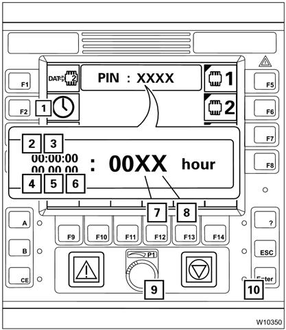
ItemDescriptionGraphicExplanation
Press the F2 button (1) repeatedly until the desired value flashes:
(2) Hours
(3) Minutes
(4) Day
(5) Month
(6) Year
•Enter the new value with the F12 button (7) and F13 button (8) or with the knob (9).
199Enter the time/date
•Enter all the required values.
•Press the Enter button (10) once, the newly entered values are accepted and displayed in the main menu.
Illogical values (e.g. 77 seconds) are not accepted and the display continues to flash.
You can cancel the input at any time; press the button. None of the values are changed.
Error Submenu
The RCL Error submenu is where you access and acknowledge any errors that are present.
Opening the Submenu been eliminated in the meantime. All existing errors are treated as new errors and displayed again after turning on the ignition.
Stop all crane movements and bring both control levers into zero position.
Press the button (2) (Figure3-102) once. The button is only active when the lamp (1) flashes or lights up.
Error Submenu
Exiting the Submenu
You can exit the Error submenu at any time. Press the button (1) (Figure3-103) once.
ItemDescription
1Selection
2Display of current error
3Display of total errors
4Error code
The same menu opens that was open before the Error submenu opened.
NOTE: All errors remain saved until you switch off the ignition, even those errors of which the cause has
5Error display
Refer to the following section for a description of each item listed above.
ItemDescriptionGraphicExplanation
You can call up all current errors with the buttons (1) and (2).
(1) Display errors in ascending order.
(2) Display errors in descending order.
1 Selection
Every time you press, the next error will be displayed.
When you keep a button pressed, all errors are shown one after the other continuously.
Item (1) shows which error is displayed.
Item (2) shows the error total. For example, 3/5 means:
•error 3 is shown
•there is a total of 5 errors. If the error shown is not acknowledged, the lamp next to the Enter button (3) lights up.
To acknowledge the error, press the Enter button (3) once.
The next, pending error is displayed and can be acknowledged.
Check whether the Error Codes, page 3-103 contain the error and the appropriate action to be taken. If the error code is not in the error code table contact Manitowoc Crane Care.
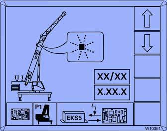
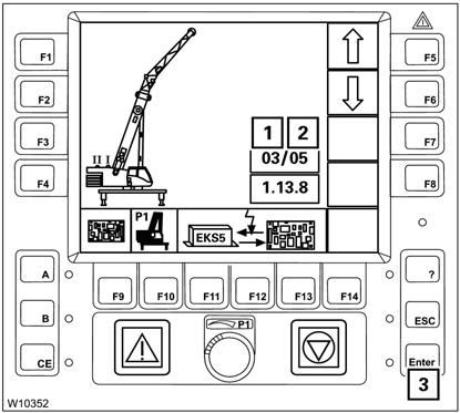
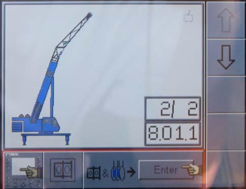
The error display includes the following symbols:
(1) the error group
(2) the faulty component
(3) the type of error
In some cases the error location (4), will have a red flashing indicator (5).
Error Codes
The following table contains a number of error codes, their causes and possible remedies.
Check whether the table contains the displayed error code. If the information in the table does not help to remedy an error, note the error code(s) down and contact Crane Care.
An error code (Figure3-105) consists, from left to right, of a one-digit number (e.g. 5), a two-digit number (e.g. 01) and a one-digit number (e.g. 2).
Error code Cause
1011...7
Error pressure sensor 1, Lower chamber
When all errors are remedied, the lamp (1) (Figure3-106) goes out.
Remedy
Switch off pressure sensor 1; Refer to Service Manual.
1018Pressure sensor 1 switched off Have malfunction rectified.
1021...7 Error pressure sensor 2, Lower chamber Switch off pressure sensor 2; Refer to Service Manual.
1028Pressure sensor 2 switched off Have malfunction rectified.
1041...7 Error angle sensor 1, Main boom
Switch off angle sensor 1; Refer to Service Manual.
1048Angle sensor 1 switched off Have malfunction rectified.
1051...7 Error angle sensor 2, Main boom
Switch off angle sensor 2; Refer to Service Manual.
1058Angle sensor 2 switched off Have malfunction rectified.
113 to 21 1
Boom extension not connected or sensor faulty
Electrically connect boom extension; if the error persists, notify Crane Care.
3033
Comparison of telescoping diagram between ECOS control and RCL resulted in differences
Compare the actual telescope status with the values on the ECOS control display and, if necessary, re-enter the telescoping position. Accept the telescope status from the ECOS control if incorrect telescope status is displayed on the RCL:
1. Press the F3 + Enter buttons once, the RCL shows the new values.
2. Press Enter to acknowledge the error.
5011
5012
There is no capacity diagram available for the entered rigging mode
Re-enter the current rigging mode. If the error is displayed again, check whether the current rigging mode is permissible.
Main boom angle too small (not steep enough) Raise the main boom.
5013Main boom angle too large (too steep) Lower the main boom.
5021 There is no RCL code available for the entered rigging mode
Re-enter the current rigging mode. If the error is displayed again, check whether the current rigging mode is permissible.
5024Boom extension angle is too small Raise the boom extension.
5025Boom extension angle is too large Lower the boom extension.
Error code
5026
5044
Cause Remedy
Current load is greater than the lift capacity, lower boom extension function is disabled
Maximum permissible swing angle exceeded
5055Minimum load value not reached
6021Fuse F1 blown
6022Fuse F2 blown
6023Fuse F3 blown
6024Fuse F11 blown
6025Fuse F12 blown
8011Rigging state not yet confirmed
8022RCL is overridden
8033
8141
8142
8143
8144
Swing gear switched ON with RCL code for working position 0°, 180° or Free-on-wheels.
1. Raise the boom extension
2. Press Enter button once
3. If necessary, increase the working radius by lowering the main boom.
Swing into a permissible working range.
When the main boom is set down, raise main boom and acknowledge the error. Notify Crane Care if the error cannot be acknowledged.
Replace blown fuse; refer to the Service Manual.
Confirming the rigging mode, Refer to Entering the Rigging Mode, page 3-81.
Cancel the override; Refer to RCL Override, page 3-73.
Switch off the swing gear.
Maximum permissible overall height exceeded1 Retract or lower.
Maximum permissible overall working radius exceeded1. Raise or retract.
Maximum permissible overall swing range exceeded1
Swing into a permissible working range.
Shutdown area of a monitored object reached1 Move into a permissible working range.
1 With working range limiter switched on.
Operating Procedures
New Crane Conditioning
Your new Grove carrier has been thoroughly tested, adjusted, lubricated, and inspected prior to delivery. For detailed engine conditioning, refer to the applicable engine manual.
The guidelines below will aid in getting a long service life out of the crane.
1. Operate as much as possible in the half to threequarters throttle or load range.
2. Avoid long periods of operation with the engine at idle or continuous maximum horsepower levels.
3. Observe instruments often and shut down at the first indication of an abnormal reading.
4. Operate to a power requirement that allows acceleration to governed speed when conditions require more power.
5. Check all components frequently for proper operation, unusual noises, and excessive heating.
6. Check the engine oil and coolant levels frequently. These guidelines should not be considered limitations but rather as a guide for familiarization of the machine and development of good operating habits.
Pre-Starting Checks
A complete walk-around visual inspection of the crane should always be made with special attention to structural damage, loose equipment, leaks, or other conditions that would require immediate correction for safety of operation. The following checklist items are suggested specifically for the operator’s benefit to make certain his crane is prepared for starting the day’s work.
Fuel Supply
Check the fuel level and make sure the cap is on tight.
Engine Oil
Check the oil level in the crankcase and fill to the FULL mark on the dipstick. Do not overfill.
Engine Coolant
Check the coolant level in the radiator and fill to the proper level. Do not overfill and check to make sure the cap is secure.
Batteries
Check that the battery cables and clamps are tight and not corroded.
Signal and Running Lights
Check all signal and running lights for proper operation. Replace burned out lamps with those of the same number or equivalent.
Foot and Parking Brakes
Check the foot and parking brakes for proper operation.
Daily Lubrication
Make certain that all components requiring daily lubrication have been serviced. (Refer to Section 5, Lubrication.)
Hydraulic Reservoir and Filter
Check hydraulic fluid quantity level and filter condition indicator. Check breather for cleanliness and ensure it is secure.
Tires
Check for severe cuts, foreign objects embedded in treads, and for correct inflation pressures. A tire inflation chart, providing the correct air pressures, is located in the Load Chart Book in the crane cab.
Wire Rope
Inspect wire rope in accordan ce with applicable Federal Regulations.
Inspect sheaves, guards, guides, drums, flanges, and any other surfaces that may come in contact with the rope for any condition that could cause possible damage to the rope.
Hook Block
Visually inspect for nicks, gouges, cracks, and evidence of any other damage. Replace any hook that contains cracks or shows evidence of excessive deformation of the hook opening, including twist. Be sure the safety latch is free and aligned.
Boom
Ensure the large access cover on top of the boom base section is in place. The boom should not be operated unless it is installed.
Air Cleaner
Check the filter condition indicator. Check filter and tubing for security.
Access Hole Covers (CE Units)
Ensure the covers are installed in all access holes in the boom and the outrigger beams.
Wind Forces
Wind can have a significant affect on loads that may be lifted by a crane. Wind forces act differently on a crane depending upon the direction from which the wind is blowing (e.g., wind on the rear of the boom can result in decreased forward stability, wind on the underside of the boom can result in decreased backward stability, wind on the side of the boom can result in structural damages, etc.). To assist you in determining prevailing wind conditions, refer to Table 3-2.
Wind forces can exert extreme dynamic loads. Manitowoc recommends that a lift not be made if the wind can cause
Wind Force
Beauford Scale Designation
Wind Velocity mph (km/h) a loss of control in handling the load. Manitowoc recommends that, if the wind speed (velocity) is between 20 mph (32 km/h) to 30 mph (48 km/h), the load capacities shall be reduced to account for the size and shape of the load and the wind direction in relation to the machine for all boom and boom extension lengths. Further, operation of the crane in wind velocities over 30 mph (48 km/h) is not recommended.
Visible Indicator
Effects of wind as observed on land
Zero (0)Calmless than 1 (<2)No wind; smoke rises vertically
1Light Air1-3 (2-5)Wind direction seen by smoke but not by wind vanes
2Light Breeze4-7 (6-11)Wind felt on face; leaves rustle; wind vane moves slightly
3Gentle Breeze8-12 (13-19)Leaves/small twigs in constant motion: wind extends flag
4 Moderate Breeze 13-18 (21-29)Raises dust & loose paper; moves small branches
Reduce crane load ratings and operating parameters at 20 mph (32 km/h)
5Fresh Breeze19-24 (31-39)Small trees in leaf begin to sway; on ponds, crested wavelets form
6Strong Breeze25-31 (40-50) Large branches in motion; telegraph wires whistle; umbrellas used with difficulty
Cease all craning operations at 30 mph (48 km/h); lower & retract boom
7Moderate Gale32-38 (52-61)Whole trees in motion; walking against wind is inconvenient
Cold Weather Operation
The following recommendations are for operating Grove cranes in very low (i.e., sub-zero) temperatures.
NOTE: Bio-Oil not suitable for operation at these temperatures. Contact Manitowoc Crane care for alternatives.
Use particular care to ensure that cranes being operated in very cold temperatures are operated and maintained in accordance with the procedures as provided by Grove. Cranes should have appropriate hydraulic oil, lubricants, and other auxiliary items required for operation in sub-zero temperatures. Individual crane functions should be operated to ensure they are sufficiently warmed prior to performing a lift.
Operation of cranes at full rated capacities in temperatures between 0°F (-18°C) and -40°F (-40°C) or lower should be accomplished only by competent operators who possess the skill, experience, and dexterity to ensure smooth operation. Shock loading shall be avoided.
Use the correct grade of oil for the prevailing temperature in the crankcase to prevent hard cranking. Diesel fuel should have a pour point of 10°F (6°C) less than the lowest expected temperature. In case of emergency, white kerosene may be added to the fuel to bring the pour point down to the required temperature to prevent clogging of filters and small passages by wax crystals. The addition of kerosene is NOT recommended for general use.
Operation Below -40°F
For crane operation below -40°F, capacities shall be de-rated 2 percent of the rated load shown on the capacity charts for each degree below -40°F.
Operation Below -40°C
For crane operation below -40°C, capacities shall be derated 3.67 percent of the rated load shown on the capacity charts for each degree below -40°C.
Preheating Hydraulic Oil
NOTE: If the oil is cold, it may take time for the solenoid valves or the power units to properly operate.
The current hydraulic oil temperature (1) is displayed in the Monitoring submenu (Figure3-107).
To open the ECOS Monitoring submenu, press the monitoring submenu button (Figure3-108) in the main menu.
Preheating
1. Set the swing gear to a maximum speed of 30%.
2. Lock the turntable.
3. Actuate the swing brake pedal.
4. While holding the swing brake on, attempt to swing the boom.
5. Observe the hydraulic oil temperature; the hydraulic oil is preheated when the display (1) (Figure3-107) shows a temperature of at least 50°F (10°C).

From 5°F (–15°C), you can perform crane movements without a load in order to speed up the preheating process.
NOTE: Operate all crane functions at least twice after preheating the hydraulic oil temperature above 50°F (10°C) in order to remove the cold oil from all parts of the hydraulic system.
Crane Warm-up Procedures
The following procedures detai l the actions that must be taken to properly warm the different crane components before operating the crane.
Temperature ranges and their effects:
• Above 50°F (10°C)
Normal crane operation is permissible without speed restriction.
• From 50°F to 32°F (10°C to 0°C)
To preheat, carry out crane movements with loads only in normal operation mode, at average engine speed and at average operating speed.
• From 5°F to 32°F (–15°C to 0°C)
To preheat, only carry out crane movements without a load. Only operate at normal speed, at medium engine speed and medium working speed.
• Below 5°F (–15°C)
Crane movements are not permitted. Preheat the hydraulic oil first.
NOTE: For temperatures below -9°C (15°F) refer to arctic lubricants and conditions in the Operator and Service Manuals.
Before starting the crane, ensure the appropriate lubricants are used to provide lubrication for the prevailing ambient temperatures in which the crane will operate in (a list of lubricants and their temperature ranges can be found in the Lubrication section of your crane’s Operator Manual , by contacting your local Manitowoc distributor, or by contacting Manitowoc Crane Care directly).
Caution
Crane Damage Hazard!
Operating the crane with the incorrect lubricants and fluids for the prevailing ambient temperature and/or failing to adequately warm the crane prior to cold weather operation can lead to a failure of a crane component or system.
Always use Manitowoc recommended lubricants and fluids for the prevailing ambient temperature and properly start and warm the crane using the cold weather procedures found in this Operator Manual and supplement before operating the crane at full load.
Engine
Warm-up Procedures for All Temperature Ranges:
1. Upon startup, allow engine to idle for 3 to 5 minutes before operating with a load.
2. Cold Engine Startup: After allowing the engine to warm by idling it for 3 to 5 minutes, slowly increase engine speed to provide adequate lubrication to bearings and allow oil pressure to stabilize.
Transmission
Caution
For full load functionality, a minimum sump temperature of 20°C (68°F) is required. Before reaching 20°C (68°F) sump temperature only neutral gear or unloaded driving is allowed, not exceeding 1500 engine RPM and not exceeding half throttle.
Operating transmission with a sump temperature below normal operating temperature is limited to:
• operating in neutral gear or
• driving with an unloaded crane while not exceeding 1500 engine RPM and not exceeding half throttle.
Warm-up Procedure
1. Engage parking brake and apply service brake.
2. Shift transmission into the highest gear and increase engine RPM to 1500 for 15 seconds, then allow engine RPM to return to idle.
3. Repeat Step 2 until temperature of transmission sump reaches normal operating temperature.
Alternate Warm-up Procedure
1. Setup crane on outriggers.
2. Engage transmission with 4-wheel drive selected (if equipped) and allow crane to run at idle until temperature of transmission sump reaches normal operating temperature.
NOTE: Warm-up operation of 4-wheel drive transmission engaged in 2-wheel drive only could cause transmission damage.
Hoist
Performing a warm-up procedure is recommended at every startup and is required at ambient temperatures below 4°C (40°F).
Warm-up Procedures:
1. Without operating hoist function, warm hydraulic oil (see Hydraulic Oil System, page 3-108).
2. Once hydraulic system is warm, operate unloaded hoist, in both directions, at low speeds several times to prime all hydraulic lines with warm hydraulic oil and to circulate gear lubricant through the planetary gear sets.
Swing Drive and Turntable Bearing
Warm-up Procedures for Temperatures Above -7°C (20°F):
1. Setup crane on fully extended outriggers, with boom fully retracted and near maximum lift angle with no load applied.
2. Rotate superstructure at a speed of less than one RPM for at least one complete revolution in one direction, then rotate superstructure at a speed of less than one RPM for at least one complete revolution in opposite direction.
Warm-up Procedures for Temperatures Below -7°C (20°F):
1. Ensure boom is fully retracted and near maximum lift angle with no load applied.
2. Rotate superstructure at a speed of less than one-half RPM for at least two complete revolutions in one direction, then rotate superstructure at a speed of less than one-half RPM for at least two complete revolutions in opposite direction.
Axles
Warm-up Procedures for Temperatures Below -35°C (-30°F):
1. Setup crane on outriggers.
2. Engage transmission (see Transmission, page 2-1) with 4-wheel drive selected (if equipped) and allow crane to run at idle until temperature of transmission sump reaches normal operating temperature.
NOTE: Warm-up operation of 4-wheel drive transmission engaged in 2-wheel drive only could cause transmission damage.
Hydraulic Oil System
Operating Limits and Warm-up Procedures:
•From 4°C to -10°C (40°F to 15°F): Crane operation without a load is allowed with medium engine RPM and medium function speed (joy stick position) until fluid reaches at least 10°C (50°F). It is then recommended that all crane functions be cycled to remove cold fluid from all components and cylinders of the hydraulic system. If there is any unusual sound coming from the crane’s hydraulic pumps or motors, stop operation and engine immediately and contact a Manitowoc distributor.
•From 10°C to 4°C (50°F to 40°F): Crane operation with a load is allowed with medium engine RPM and medium function speed (joystick position) until fluid reaches at least 10°C (50°F).
•From 95°C to 10°C (200°F to 50°F): Crane operation with a load is allowed with no restrictions.
•Above 95°C (200°F): No crane operation is allowed. Let crane’s hydraulic oil cool by running engine at idle with no functions actuated.
Battery Disconnect
The battery disconnect switch is located near the battery box and the left rear wheel on the left side of the crane. To disconnect the batteries, place the battery disconnect switch to OFF. Place the switch to ON to connect the batteries.
Engine Operation
Starting and shutdown procedures for most diesel engines generally follow the same pattern. Therefore, the following procedures can be applied except where specific differences are noted. (Refer to the applicable engine manufacturer’s manual for detailed procedures.)
Starting Procedure
Make an under-the-hood inspection for fuel, oil, and coolant leaks, worn drive belts, and trash build-up.
If the crane was inactive for over 24 hours and the batteries were disconnected, make sure to connect the batteries before proceeding with start-up procedure.
Warning
Diesel engine exhaust can be harmful to your health. Only operate the engine in a well ventilated area or vent exhaust outside.
Before starting the engine, apply the parking brake and engage the swing lock.
Caution
Never crank the engine for more than 30 seconds during an attempted start. If the engine fails to start after 30 seconds, stop and allow the starter motor to cool for approximately two minutes before attempting another start.
If the engine fails to start after four attempts, correct the malfunction before attempting further starts.
Damage to the starter or other components could result if these warnings are not followed.
Warm Engine
Warning
Do not spray starting fluid into the air inlet. The spray will contact the heater elements and could explode causing personal injury.
NOTE: The engine ECM monitors the engine and, under certain conditions, cycles the air heater on and off at start-up and during operation.
The engine is equipped with an electric air heater grid at the air inlet elbow to aid in cold starting and reduce white smoke at start-up. In the preheat mode, the engine should not be cranked until the WAIT-TO-START lamp turns off.
1. Ensure the service brake pedal is depressed, parking brake is set and the transmission is in neutral.
NOTE: Engine will not crank unless service brake pedal is depressed and transmission shift lever is in neutral.
2. Turn the IGNITION switch to START and release immediately when the engine starts. Do not push or hold the throttle down. The ECM will automatically provide the proper amount of fuel to start the engine.
3. Immediately check the engine instruments for proper indications after starting. Shut down the engine if the oil pressure gauge does not reach the proper reading within 15 seconds.
Caution
If temperature indicator(s) do not display proper readings, shut down the engine and correct the malfunction before resuming operation.
4. Allow engine to warm up at least five minutes before applying a load. Do not race engine for a faster warmup.
Cold Engine
Warning
Do not spray starting fluid into the air inlet. The spray will contact the heater elements and could explode causing personal injury.
NOTE: The engine ECM monitors the engine and, under certain conditions, cycles the air heater on and off at start-up and during operation.
The engine is equipped with an electric air heater grid at the air inlet elbow to aid in cold starting and reduce white smoke at start-up. In the preheat mode, the engine should not be cranked until the WAIT-TO-START lamp turns off.
1. Ensure the service brake pedal is depressed, parking brake is set and the transmission is in neutral.
NOTE: The engine will not crank unless the service brake pedal is depressed and the transmission shift lever is in neutral.
2. The WAIT-TO-START lamp is illuminated during the preheat time that takes place when the IGNITION switch is in the ON position during cold weather starting. To minimize cranking time during cold weather starting, the engine should not be cranked until the WAIT-TO-START lamp turns off.
3. Turn the IGNITION switch to START and release immediately when the engine starts. Do not push or hold the throttle down. The ECM will automatically provide the proper amount of fuel to start the engine.
4. Immediately check the engine instruments for proper indications after starting. Shut down the engine if the oil pressure warning light remains lit for 15 seconds.
Caution
If the temperature indicator does not display proper reading or the oil pressure light remains on, shut down the engine and correct the malfunction before resuming operation.
5. Allow the engine to warm up at least five minutes before applying a load. Do not race the engine for a faster warmup.
Detailed cold weather starting and operating procedures are covered in the engine manual.
Idling the Engine
Idling the engine unnecessarily for long periods of time wastes fuel and fouls injector nozzles. Unburned fuel causes carbon formation, oil dilution, formation of lacquer or gummy deposits on the valves, pistons, and rings, and rapid accumulation of sludge in the engine.
NOTE: When prolonged idling is necessary, maintain at least 800 rpm.
Racing the Engine
NEVER race the engine during the warm-up period. NEVER operate the engine beyond governed speed (as might occur in downhill operation or downshifting). Engine bearings, pistons, and valves may be damaged if these precautions are not taken.
Shutdown Procedure
1. Allow the engine to operate at fast idle for about five minutes to avoid high internal heat rise and allow for heat dissipation.
2. Turn the ignition switch to OFF.
Diesel Particulate Filter (Tier 4 Engines Only)
The Exhaust System Cleaning Indicator is displayed in the warning screen. This indicator illuminates red when the diesel particulate filter is getting filled with soot and needs to be cleaned out.
When the Exhaust System Cleaning indicator illuminates or flashes start the regeneration process.
The indicator will be lit continuously during the early stages of clogging. If the system continues to clog, the indicator will begin to flash and a slight engine derate will occur.
If even more clogging occurs, the engine warning indicator will illuminate in addition to the Exhaust System Cleaning indicator and a severe engine derate will occur.
Warning
Extreme Heat Hazard!
During the regeneration process the exhaust becomes very hot. Do not park the vehicle near objects that are flammable.
Use caution near the exhaust tailpipe as it will also become very hot.
The regeneration process can take place in three different modes:
Passive: the exhaust is hot enough during normal working operation to burn off any hydrocarbon (soot) accumulation
Active : Active self-regeneration occurs when there is not sufficient heat in the exhaust to convert all the hydrocarbon being collected in the Exhaust System Cleaning. Exhaust temperatures are raised by injecting a small amount of fuel. The resulting chemical reaction raises exhaust gas temperatures high enough to oxidize the hydrocarbon from the filter. This is all done without any operator intervention.
Manual: Manual or stationary, exhaust system cleaning is the same as active exhaust system cleaning but takes place while the equipment is not being operated. It offers the equipment operator the option, if needed, of performing exhaust system cleaning outside the normal duty cycle.
Transporting Crane
Caution
Machine Damage Hazard!
Dead end lug not to be used as tie down point for boom during transportation. Failure to comply may result in machine damage. When boom is secured for transport, boom shall not be constrained. All ties downs must allow reasonable freedom of movement.
Crane Travel Operation
Traveling — General
Warning
Inadvertent Operation Hazard!
Before traveling, ensure the crane function switch is in the off position. This will prevent inadvertent operation of craning functions due to bumping of the controllers while traveling.
RT machines are subject to the same road regulations as any truck, regarding gross weight, width, and length limitations.
Although RT machines are specifically designed for rough terrain, the operator should be extremely cautious and aware of the terrain in which he is operating.
Danger
Tipping Hazard!
Avoid holes, rocks, extremely soft surfaces, and any other obstacles which might subject the crane to undue stresses or possible overturn.
Do not drive the crane with the boom off center because automatic oscillation lockout will occur, making the crane subject to tipping on uneven surfaces. Center the boom over the front, turn the Swing Brake Switch to ON and engage the Turntable Lock Pin (if equipped).
Fully retract the boom and ensure the swingaway jib is properly stowed and secured.
Caution
Machine Damage Hazard!
Traveling at speeds greater than 16km/h (10mph) with the fixed counterweight installed and the boom extension stowed can result in axle failure if the boom angle is less than 10°.
When traveling at speeds greater than 16km/h (10mph) in the above configuration, ensure that the boom is elevated to an angle between 10° to 20° and the hook block is stowed in the storage tray.
Caution
Machine Damage Hazard!
Traveling at speeds greater than 16km/h (10mph) with the hydraulically removable counterweight installed and the boom extension stowed can result in axle failure if the boom angle is less than 15°.
When traveling at speeds greater than 16km/h (10mph) in the above configuration, ensure that the boom is elevated to an angle between 15° to 20° and the hook block is stowed in the storage tray.
Caution
Machine Damage Hazard!
Do not travel with an empty hook in a position where it can swing freely (except where noted). Either remove the hook block and/or headache ball from the hoist cable(s) and stow securely or make sure the hook block or headache ball is properly secured to the tie down provided for that purpose.
Do not drive the crane with the lift cylinder bottomed. At a minimum, position the boom slightly above horizontal. Fully retract the outrigger jacks and properly store the floats.
Disengage Main Hydraulic Pump via pump disconnect for cold weather starting of the engine (Sub-Zero). Pump must be re-engaged for travel.
Caution
Machine Damage Hazard!
Manitowoc recommends towing or pulling another vehicle with the optional pintle hook (if equipped) or by attaching at a point no higher than the pintle hook height, or severe damage may occur to the drivetrain.
Do not tow or pull by attaching to the tie-down lugs unless the attaching point is no higher than the pintle hook height.
Use four-wheel drive when greater traction is necessary to avoid severe damage to the drivetrain. Should the crane become mired down, use a tow truck or tractor to free the vehicle. Severe damage to the drivetrain may occur if the operator attempts to free the crane unassisted.
• Use four-wheel drive only when greater traction is necessary. (Refer to Four-Wheel Drive Operation, page 3-114 for operating instructions.)
• Ensure the outrigger beams and jacks are fully retracted with the floats properly stowed.
• Conduct all travel with the assistance of a ground person to warn the operator of any changing conditions in the terrain being traversed.
The owner/lessee must take appropriate measures to ensure that all persons operating or working with the affected models are in compliance with The Manitowoc Company, Inc. recommendations. The operator of the crane assumes responsibility for determining the suitability of traveling conditions. Traveling under the controlled conditions specified in these guidelines , must be conducted with the utmost diligence and care to ensure the safety of all personnel performing the operation and/or working around the crane.
Traveling — Towing/Pulling
Caution
Machine Damage Hazard!
Manitowoc recommends towing or pulling another vehicle with the optional pintle hook (if equipped) or by attaching at a point no higher than the pintle hook height, or severe damage may occur to the drivetrain.
Do not tow or pull by attaching to the tie-down lugs unless the attaching point is no higher than the pintle hook height.
Use four-wheel drive when greater traction is necessary to avoid severe damage to the drivetrain.
Should the crane become mired down, use a tow truck or tractor to free the vehicle. Severe damage to the drivetrain may occur if the operator attempts to free the crane unassisted.
To avoid severe damage to the drive train while using the crane to tow or pull another vehicle, follow these recommendations:
• Ensure the boom is in a horizontal position and not elevated above 0°.
• Ensure the outrigger beams and jacks are fully retracted with the floats properly stowed.
• Tow or pull on open ground when possible.
• Connect to the optional pintle hook (if equipped) or attach cables/straps to the crane at a point no higher than the pintle hook height.
• Use four-wheel drive when greater traction is necessary. (Refer to Four-Wheel Drive Operation , page 3-114 for operating instructions.)
• Should the crane become mired down, use a tow truck or tractor to free the vehicle. Severe damage to the drivetrain may occur if the operator attempts to free the crane unassisted.
• Conduct all travel with the assistance of a ground person to warn the operator of any changing conditions in the terrain being traversed.