10 minute read
RT9150E OPERATOR MANUALOPERATING CONTROLS AND PROCEDURES


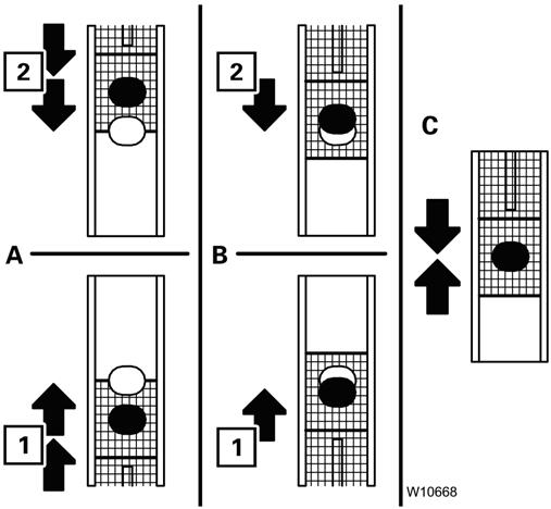
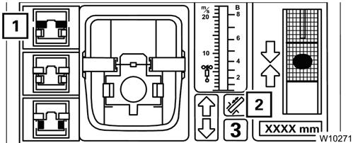
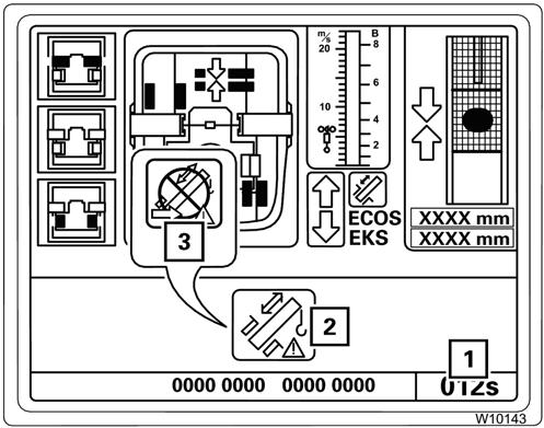
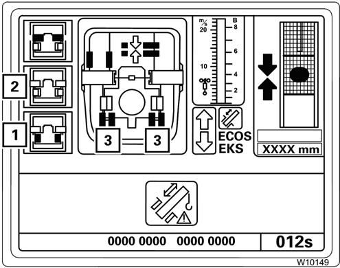
Near a locking point, the displa y (3) indicates the following, refer to (Figure3-163):
Lock Telescope Cylinder
The telescope cylinder must be locked to a telescopic section so that the telescopic section can be moved.
Prerequisites
Refer to Figure3-164.
• The distance to the locking point;
(A) Yellow: Approx. 1 m (3.3 ft)
(B) Yellow: Less than 1 m (3.3 ft)
(C) Green: At the locking point and
• The direction of travel to the locking point;
(1) Extending
(2) Retracting
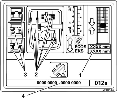
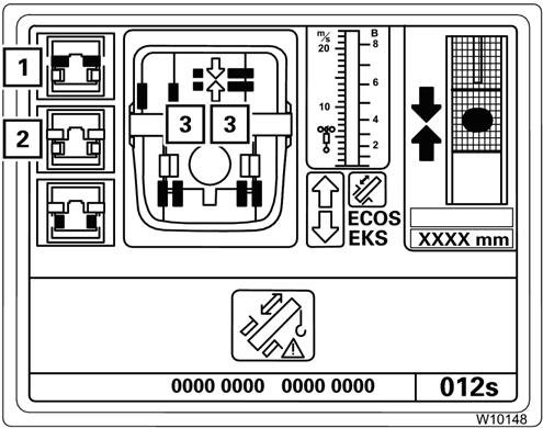
In order to lock the telescope cylinder the following conditions must be met:
• The telescoping mechanism must be on, symbol (3) green
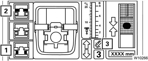
• The telescopic section must be locked, symbol (2) grey
• The telescope cylinder must be unlocked, symbol (1) yellow.
To Select Lock
Refer to Figure3-165.
1. Move the telescope cylinder to the desired locking point, e.g. to telescopic section 3.
Wait until the display (2):
(A): shows the desired telescopic section or,
(B): shows no telescopic section and the desired locking point is reached next.
2. Press the F2 button (1) once, The symbol (1) flashes indicating that locking the telescope cylinder is selected.
Locking the Telescope Cylinder
Refer to Figure3-166.
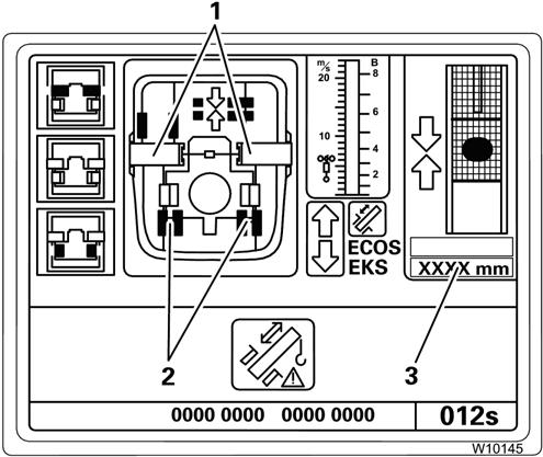
In order to unlock a telescopic section the following conditions must be met:
• The telescoping mechanism must be on, symbol (2) green
• The telescopic section must be locked, symbol (1) grey.
To Select Unlock
Refer to Figure3-168.
Move the control lever until locking is complete:
• The cylinder locking pins (3) extend into the locking point;
- Yellow: Intermediate position
- Green: Locked.
• When the cylinder is locked:
- the symbol (1) is yellow,
- the symbol (2) is grey,
- the cylinder locking pins (4) are green.
Unlocking the Telescopic Section
Unlocking a telescopic section is required for that section to be moved.
NOTE: The telescope cylinder and a telescopic section cannot be unlocked simultaneously.
Prerequisites
Refer to Figure3-167.
Press the F1 button (1) once:
• If the telescope cylinder is locked, symbol (1) flashes indicating that the unlock telescopic section process has been selected.
• If the telescope cylinder is unlocked, symbol (2) flashes and the following is selected:
- Lock the telescope cylinder,
- Unlock the telescopic section.
In the next step, both of the previous selections are carried out one directly after the other.
Unlocking the Telescopic Section
Refer to Figure3-169.
Move the right control lever for telescoping.
• If necessary, the telescope cylinder locking pins (3) will extend first.
• The section locking pins will (2) retract: Yellow: Intermediate position, Red: Unlocked.
In the unlocked position, the symbol (1) is yellow. If the control lever is moved, the telescopic section is telescoped immediately.
If the symbol (1) (Figure3-170) is still flashing after approximately 10 seconds, this means that the section locking pins are under load.
Let go of the control lever.
To relieve the load, carefully retract and extend the boom a little.
Caution
Boom Damage Hazard!
Repeated attempts to extend and retract may cause damage to the boom system.
NOTE: If removing the load does not cause unlocking, you must lock the telescopic section again and restart the unlocking process, refer to Lock Telescope Cylinder, page 3-142.
Telescoping the Telescopic Section
You can telescope the telescopic section once it is unlocked.
Prerequisites
Refer to Figure3-171.
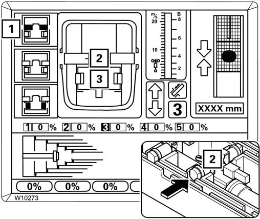
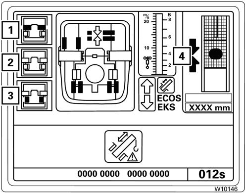
In order to telescope a section it must be unlocked, the following conditions must be met:
• The telescoping mechanism must be on, symbol (3) green
• The telescope cylinder must be locked, symbol (1) grey
• The telescopic section must be unlocked, symbol (2) yellow.
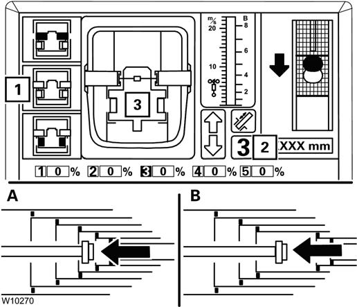
Telescoping
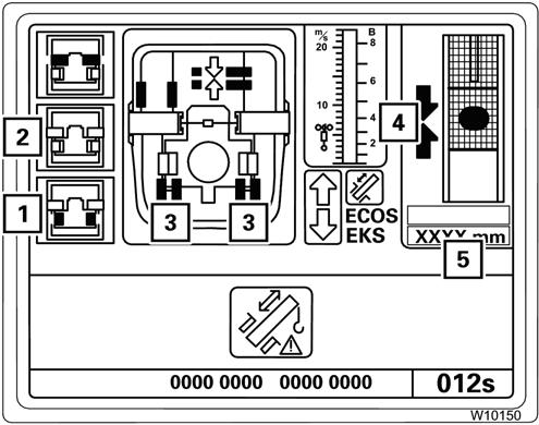
Refer to Figure3-172.
Move the right control lever in the desired telescoping direction.
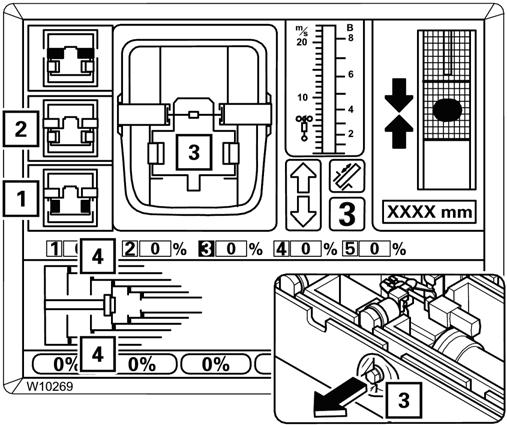
The display (2) shows the currently extended length in percent, e.g. 55% for telescopic section 3.
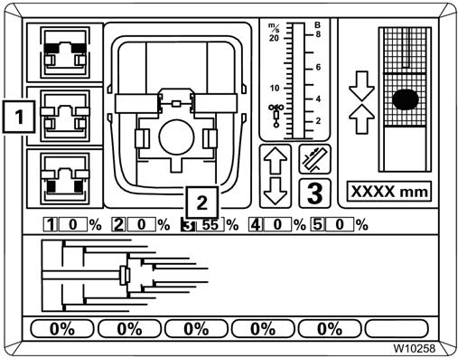
The current telescope diagram on the display (1) changes continually.
Locking the Telescopic Section
Every telescopic section can be locked at the fixed lengths, refer to Fixed Length, Intermediate Length, Telescoping Length, page 3-132.
Prerequisites
Refer to Figure3-173.
3-146
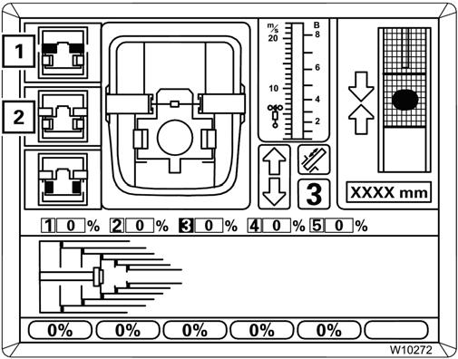
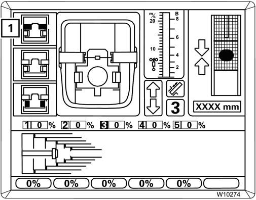
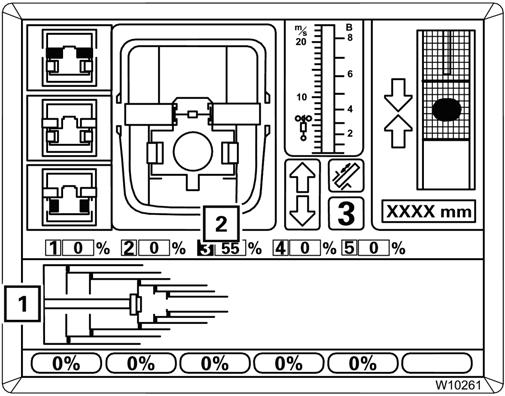
In order to lock a telescopic section the following conditions must be met:
• The telescoping mechanism must be on, symbol (3) green
• The telescopic section must be unlocked, symbol (2) yellow
• The telescope cylinder must be locked, symbol (1) grey.
To Select Lock
Refer to Figure3-174.
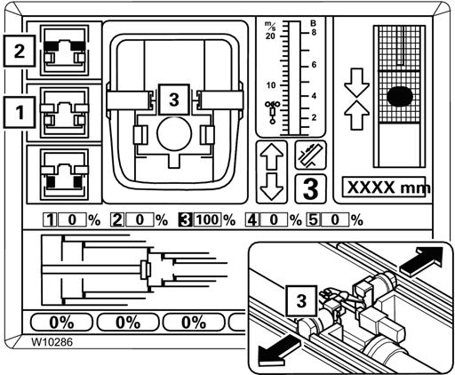
1. Telescope to the desired fixed length, e.g. telescopic section 3 to 100%.
If necessary, wait until the telescopic section moves past a non-desired fixed length by approximately 5%, e.g. at 50%, display (2).
Published 2-18-2016, Control # 614-00
2. Press the button (1) once, the symbol (1) flashes indicating that lock telescopic section is selected.
Locking the Telescopic Section
Refer to Figure3-175.
Telescoping Main Boom in Horizontal Position
Position the main boom to the horizontal position as described in Lowering the Boom to a Horizontal Position, page 3-131.
The RCL automatically switches to the corresponding rigging table. It specifies the maximum permissible telescoping where extending is switched off, refer to the shutdown values in the Load Chart.
1. Set down the load.
2. Extend the main boom only until the RCL switches off the extension procedure.
NOTE: If you continue to extend the main boom after a RCL shutdown, you may enter ranges in which you can neither perform retraction operations nor raise the boom.
Telescoping with Rigged Boom Extension
Caution
Boom Damage Hazard!
Move the right control lever until locking is complete:
• The section locking pins (3) extend at the locking point:
Yellow: Intermediate position
Green: Locked
• The notch in the section locking pins engage the telescopic section is set down.
In the locked position:
• The symbol (1) is yellow,
• The symbol (2) is grey.
NOTE: Ensure the telescopic section is locked and the locking pins engaged with the section, the symbol * must be yellow.
This prevents the load from exerting pressure on the telescope cylinder and allows the load to be enabled for fixed lengths.
Do not rotate the superstructure while telescoping the main boom with a rigged boom extension. Damage to the boom may occur.
The telescoping of the main boom with a rigged boom extension is monitored by the RCL. Telescoping will only be enabled if the main boom is raised to a certain angle and a maximum permissible load is not exceeded.
The required angle (between 70° and 78°) depends on the rigging mode of the crane.
You will find the required main boom angle and the maximum permissible load (weight of the hook block) in the Load Chart.
If the main boom angle is too small for telescoping with the rigged boom extension, the RCL shows the corresponding error message.
Extending/Retracting the Boom
Danger
Crushing and Hazard!
Check the load chart for the maximum load at a given radius, boom angle, and length before extending the boom with a load.
Death or serious injury could result from the crane tipping over or being crushed by moving machinery.
Caution
Machine Damage Hazard!
When extending the boom, simultaneously let out the hoist cable to prevent two-blocking the boom nose and hook block.
When retracting the boom, the load will lower unless the hoist cable is taken in at the same time.
To extend or retract the boom, use the controls on the righthand armrest:
1.
3. Using the right-hand joystick controller:
-Extend; push the controller to the right, and hold until the boom is at the desired position.
-Retract; push the controller to the left, and hold until the boom at the desired position.
4. Push the top of the Telescope switch again to turn off the function.
Telescope Emergency Program
Refer to Figure3-176.
In the event of a malfunction in the telescoping mechanism, you can retract the main boom with the Telescoping emergency program.
NOTE: The emergency program is not intended for crane operation and is therefore restricted to a certain amount of time.
Starting the Emergency Program
Only start the emergency program when the z symbol is displayed, refer to Telescope Mechanism Error Messages, page 3-37.
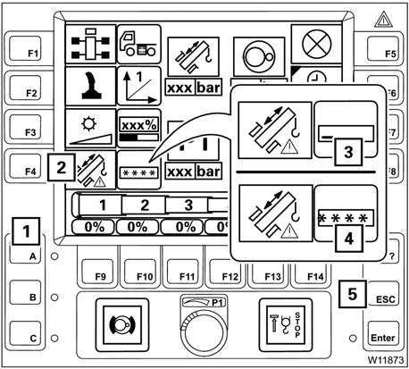
1. Press and hold the right dead man's switch.
2. Additionally press the button (2) (Figure3-176) once –symbol (3) appears.
To access the telescope emergency program:
1. Press and hold the right dead man's switch
2. Press the F4 button once: the display changes so you can enter the emergency keycode (3)
3. Press the buttons (1) in the order:
4. The symbols shown (4) confirm the entry.
If your input was incorrect, all the symbols (4) go out and you need to repeat the input.
You can cancel the entry at any time using the Esc button (5).
FIGURE3-177
After correct input, the symbol (1) (Figure3-177) is displayed, the Telescope Emergency Program starts.
5. Press the Esc button to open the Main Menu and press the Telescope button , F5 once.
6. The Telescoping submenu opens, refer to (Figure3-178).
The emergency program is active if:
• The symbol (2) is displayed and
• the display (1) is shown; a time span of about 360 seconds elapses.
The telescoping mechanism can be operated with the emergency program within this time.
After this time has elapsed, the symbol (3) appears, and you need to restart the emergency program.
Determining the Type of Error
Refer to Figure3-179.
Caution
Equipment Damage Hazard!
In emergency mode, there is no monitoring of prerequisites; functions are performed immediately after pressing a button.
Ensure you constantly monitor the status of the telescoping mechanism before you initiate locking or unlocking.
Check which emergency program procedure is suitable for the current error:
• If the display (1) shows no value, there is an error on the length indicator.
• If a symbol (2) is violet, there is an error on the proximity switch.
• The buttons next to the symbols (3) are active. After pressing the button, locking or unlocking is performed immediately.
NOTE: Note down the error code (4) first if you intend to contact Crane Care before carrying out the emergency program.
Caution
Equipment Damage Hazard!
Never telescope the main boom if there is an error on the length indicator and on the proximity switch at the same time.
It would then not be possible for you to monitor operations, and components in the main boom could be damaged, or a situation could arise in which the main boom can no longer be extended or retracted.
NOTE: In the Telescope Emergency Program, all functions for retracting the main boom remain enabled as long as there are no other errors (hydraulic or mechanical).
The speed is restricted to approximately 30% of the maximum speed.
Refer to If There is an Error at a Proximity Switch, page 3151 or the following section if there is an error on the length indicator.
If There is an Error on the Length Indicator
Refer to Figure3-180.
First note down the current status of the telescoping mechanism:
• Check the positions of the locking pins as usual, i.e. on the displays (1) and (2).
• Check whether the display (3) shows the RCL measured value for the extended length of the telescope cylinder.
• Check the telescoping on the RCL.
Inspections Prior to Telescoping
Refer to Figure3-181.
Warning
Unintended Operation Hazard!
Press the * , F1 button (1) for unlocking the telescopic section no more than twice
If this does not start the unlocking procedure, contact Crane Care.
Serious injury or death may occur from sudden retraction of the telescopic section.
Before telescoping, check that the following conditions are met:
• The telescoping cylinder is locked, symbol (3) is grey.
• The telescopic section is unlocked (press no more than twice), symbol (1) is yellow.
• Locking is not selected, symbol (2) is grey.
• The telescope cylinder is at the locking point, the arrows (4) are green.
Retracting and Locking A Telescopic Section
Refer to Figure3-182.
Caution
Equipment Hazard!
Selecting Lock during telescoping will cause the locking pins on the telescopic section to slide out immediately and damage or tear the electrical or hydraulic components in the main boom.
Unlocking the Telescope Cylinder
Refer to Figure3-183.
Warning
Unintended Operation Hazard!
Press the * , F1 button (1) for unlocking the telescopic section no more than twice
If this does not start the unlocking procedure, contact Crane Care.
Serious injury or death may occur from sudden retraction of the telescopic section.
During telescoping you must not select Lock. Under no circumstances should you press the F2 button (2).
1. Retract the telescopic section slowly and as far as possible.
2. Press the F1 button (1) once.
3. Extend the section approximately 1.38 in (35 mm).
The telescopic section should be locked. In locked position:
- The locking pins (3) are green,
- the symbol (1) is grey,
- the symbol (2) is yellow.
4. Engage the locking pin notch with the section and retract the telescopic section as far as it will go.
If the telescopic section is locked, you can now unlock the telescoping cylinder by pressing the F3 button (1) once (at the most twice).
The telescoping cylinder should be unlocked. In the unlocked position:
- The locking pins (3) are red,
- the symbol (1) is yellow,
- the symbol (2) is grey.
You can now move the telescoping cylinder into the next telescopic section.
Extending and Locking the Telescope Cylinder
Refer to Figure3-184.
Caution
Equipment Hazard!
Selecting Lock during telescoping will cause the locking pins on the telescopic section to slide out immediately and damage or tear the electrical or hydraulic components in the main boom.
If There is an Error at a Proximity Switch
Refer to Figure3-185.
You may not select Lock while the telescope cylinder is retracting or extending. Under no circumstances should you press the F3 button (1).
1. Slowly move the telescope cylinder into the next extended telescopic section.
At the locking point:
- the arrows (4) are green,
- the display (5) shows the length for the current locking point, refer to Tables for Approaching the Locking Points, page 3-153.
2. Press the F3 button (1) once.
The telescope cylinder is locked. In Locked position:
- The locking pins (3) are green,
- the symbol (1) is grey,
- the symbol (2) is yellow.
3. You can now retract this telescopic section, refer to Retracting and Locking A Telescopic Section, page 3150.
Faulty proximity switches are shown in violet.
The displays (A), (B) and (C) only show the current positions when all the corresponding proximity switches are free of error.
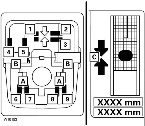
Several proximity switches are related to the displays (A), (B) and (C).
A: Proximity switches (6) to (9)
B: Proximity switches (4) and (5)
C: Proximity switches (1) to (3)
When a proximity switch is faulty (violet), then:
• The corresponding locking pins on the displays (A) and (B) are always yellow.
• The corresponding arrows are not shown on the display (C).
When an error occurs, you can determine the current position more precisely based on the other, fault-free proximity switches. The proximity switches show the following positions:
• Display (C): Telescoping cylinder at the locking point
(1) At the locking point
(2) Behind the locking point
(3) In front of the locking point
• Display (B): Telescopic section locked
(4) Locked
(5) Unlocked
• Display (A): Telescoping cylinder locked