6 minute read
ItemDescriptionGraphicExplanation


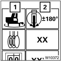
• Start Input mode: press the F2 button (1) once, symbol turns green
• Input mode on: press either the F5 button or the F6 button once, to bring up the next outrigger configuration(2):
100%, full extend
50%, mid-extend.
Refer to Outrigger Deployment, page 3-82.
• Start Input mode: press the F3 button (1) once, symbol turns green
• Input mode on: press either the F5 button or the F6 button once, to bring up the next permissible swing range (4):
(1) 360° swing range
(2) Working position 0° to the rear *
(3) Working position 180° to the front *
* Swing gear must be off.
Refer to Swing Range, page 3-83.
• Start Input mode:
For main hoist: press the F4 button (4) until symbol (1) is green
For auxiliary hoist: press the F4 button (4) until symbol (2) is green
• Input mode on: press either the F5 button or the F6 button once: To change reeving by one line (3) and display the relevant maximum load (5) for that reeving.
Refer to Entering the Reeving, page 383.
Maximum load in tons (t) or kilo pounds (klbs) for displayed RCL code.
Refer to the RCL Monitoring Submenu, page 3-86 for more information.
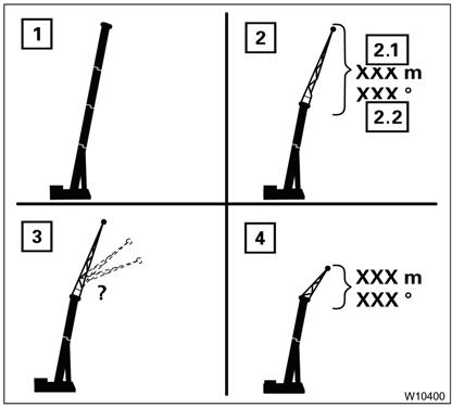
Boom configuration for displayed RCL code:
(1) Main boom/auxiliary singlesheave boom nose
(2) Boom extension:
(2.1) Length
(2.1) Angle
(3) RCL rigging code for the boom extension angle entered
(4) Heavy load boom extension
Refer to Boom System, page 3-82.
When in input mode:
(1) Press the F5 button (1) once, next greater value is displayed
To turn input mode on:
For boom system:
Press the F7 button (3) until symbol (2) is green.
For length and angle of boom extension:
(2) Press the F6 button (2) once, next smaller value is displayed. 8
Press the F7 button (3) until symbol (1) is green
When in input mode:
Press the F7 button (3) once, the next available length is displayed (4).
To turn input mode on:
Press the F9 button (1) once, the symbol turns green.
With input mode on:
Refer to Boom System, page 3-82. 9
Press either the F5 button or the F6 button until the desired RCL code is displayed (2).
Refer to Entering the RCL Code, page 3-83.
Entering the Rigging Mode
In the Rigging Mode submenu there are two ways of entering the current rigging mode.
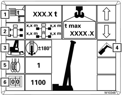
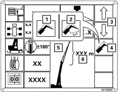
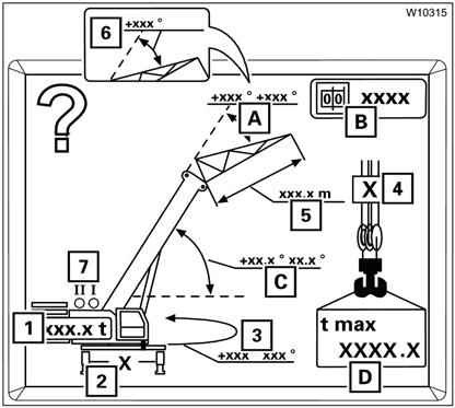
• Either enter the individual components (1) to (5) (Figure3-76) one after the other or
• Enter the RCL code (6) and the current reeving (5). Then you must confirm and accept the newly entered rigging mode.
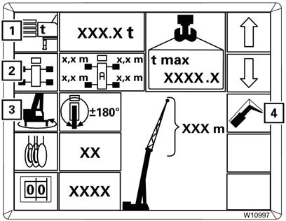
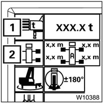
• counterweight (1)
• boom system (4)
• outrigger span (2)
• swing range (3)
In this order, the values that can be selected for the current entry are always restricted by the previous entry. As a result, already entered values do not change.
The following section describes the input procedure based on the individual components. If you want to enter the rigging mode based on the RCL code, refer to Entering the RCL Code, page 3-83.
Entering Individual Components
With this type of input, select all the components of the rigging mode one after the other.
Warning
Tipping Hazard!
Values which have already been set may change when entering individual components. Always compare the displayed rigging mode with the current rigging mode of the crane after making an entry, this will prevent the RCL from calculating with incorrectly set components and the crane from becoming overloaded or overturning.
Serious injury or death may result from improper RCL data.
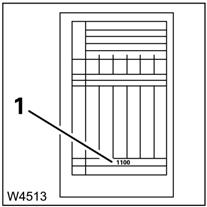
When re-entering the rigging mode completely, you can prevent already entered components from changing by making entries in the following order (Figure3-77):
When entering the components, the corresponding RCL code (2) (Figure3-78) is displayed at the same time.
Then you must enter the current reeving (1) and accept the indicated rigging mode
To Switch ON Input Mode
Press one of the buttons (1) to (4) (Figure3-77) for the desired component.
The corresponding symbol turns green, input mode is switched on.
Selecting Values
With the input mode switched on, you can select values that are permissible according to the Load Chart.
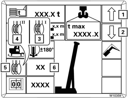
The following example is for se lecting the values for the counterweight, symbol (1) (Figure3-79) green.
Counterweight
Boom System
For more information about using a boom extension refer to, Boom Extensions, page 3-155.
Press the F5 or F6 button (4) or (5) repeatedly until the display (2) shows the rigged counterweight version:
(4) Larger versions,
(5) Smaller versions.
The display (7) indicates the corresponding RCL code, the symbol (6) indicates the RCL code is being determined.
The display (3) indicates the maximum load for the displayed rigging mode and the displayed reeving.
You can cancel the input at any time. Press the button. The main menu opens.
After the selection procedure, there are three options:
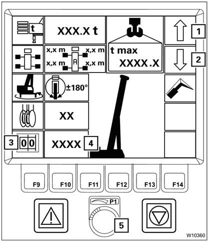
• Switching off the input mode:
Press the F1 button (1) (Figure3-80) once, symbol turns grey.
• Switching the input mode:
Press the button for the next component once, for example, the F2 button (2), the symbol turns green.
• Accept the displayed rigging mode. Refer to Approve the Rigging Mode, page 3-84.
1. Press the button (4) (Figure3-81) repeatedly until the symbol for the required input is green.
(1) Boom system entry
(2) Boom extension length/angle input
2. Press the button (3) repeatedly until:
- the display (5) shows the rigged boom system, e.g. the boom extension or
- until the display (6) shows the rigged boom extension length, and in the case of a luffing boom extension, the rigged boom extension angle.
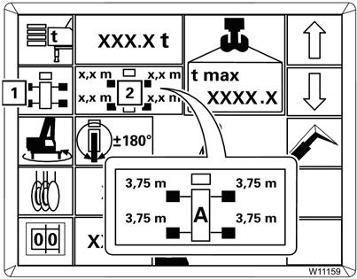
Outrigger Deployment
Refer to Figure3-82.
Enter the other components of the current rigging mode in the same way.
With symbol (1) green, function ON. Press the buttons to select:
- 100%, fully extended
- 50%, mid-extend position
- 0%, retracted.
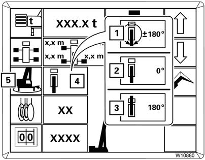
Swing Range
Symbol (1) (Figure3-83) is green. Press the buttons repeatedly until the display (2) indicates the required swing range, e.g. 360°.
You can only confirm rigging modes for swing ranges other than 360°:
• if the swing gear is switched off in the 0°/180°/Free on wheels working position.
• if the superstructure is in the entered swing range. If necessary, first enter the 360° swing range and swing the superstructure into the required position.
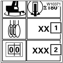
Entering the RCL Code
You must enter the RCL code for the rigging mode according to the Lifting Capacity Table.
1. Select the RCL code with the switch (5). The other displays show the corresponding rigging mode. Now you can enter the reeving and accept the rigging mode.
Refer to the Load Chart for the current rigging mode. The corresponding RCL code (1) (Figure3-84) is specified at the bottom of the table (e.g. 1100).
1. Press the button (3) (Figure3-85) once, symbol green.
2. Press the button (1) or (2) repeatedly until the display (4) shows the required RCL code. or
Entering the Reeving
Entering the reeving does not have an effect on any other component that has already been entered.
1. Press the button (5) (Figure3-86) repeatedly until the symbol for the hoist with which you want to lift the load has turned green:
(3) Symbol for main hoist
(4) Symbol for auxiliary hoist
2. Press the button (1) or (2) repeatedly until the display (6) shows the number of currently reeved rope lines.
Approve the Rigging Mode
Prior to crane operation, you must confirm and accept the newly entered rigging mode.
FIGURE3-87
Confirming Rigging Mode
To confirm the rigging mode, press the button (2) (Figure3-87) once:
• If the rigging mode is permissible, the lamp (1) goes out. The Rigging Mode Monitoring Submenu, page 3-85 opens and you can approve the rigging mode.
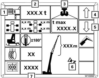
Check the following (Figure3-89):
• (1) The rigged counterweight
• (2) The rigged outrigger span
• (3) The swing range for the planned job
FIGURE3-89
FIGURE3-88
• If the rigging mode is not permissible, the lamp (1) (Figure3-88) lights up. Press the button (2) once to display the error codes, refer to Error Codes, page 3103.
Accepting Rigging Mode
You must check whether the current rigging mode of the crane corresponds to the displayed rigging mode.
Warning
Tipping Hazard!
If the actual rigging mode varies from the displayed rigging mode, the maximum load displayed by the RCL will not correspond to the permissible lifting capacity allowed in the Load Chart. Inaccurate programming of the RCL allows the crane to be improperly operated. Serious injury or death may occur if the crane is overloaded or overturns.
• (4) The number of reeved rope lines
• (5) The length of the rigged boom extension
• (6) The angle of the rigged boom extension
• (7) The hoist that is switched on, to switch over hoists, refer to Entering the Reeving, page 3-83.
For the rigging mode, the following is displayed:
• (A) The permissible working range of the boom extension
• (B) The RCL code
• (C) The permissible working range of the main boom
• (D) The maximum load
If you need to correct some values, press the button. The Rigging Mode Submenu, page 3-78 opens.
If the current rigging mode is displayed, press the button. The RCL Monitoring Submenu, page 3-86 opens, and the crane movements are enabled provided no error is pending.