5 minute read
OPERATING CONTROLS AND PROCEDURESRT9150E


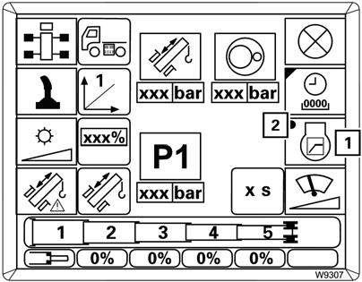
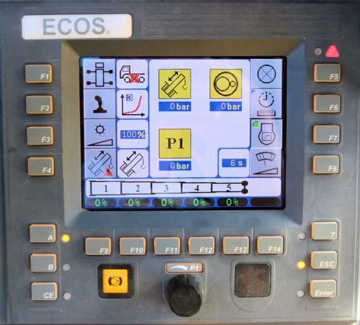
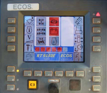
Settings Submenu
Press the settings submenu button (Figure3-47) in the main menu to open this submenu.
Settings Submenu
FIGURE3-47
ItemDescription
1Outrigger control graphic
2Setting control lever characteristics
3Setting the display brightness
4Telescoping emergency program access
5Lamp test
6Operating hours submenu
7Critical load control, on/off
8Current telescoping mechanism status display
9Telescoping cylinder hydraulic pressure
10Swing gear hydraulic pressure
11Hydraulic circuit pressure
Refer to the following table for a description of each item listed above.
The characteristic curve that is currently set is shown on the display.
• Repeatedly press the F2 button until the desired characteristic curve is displayed.
There are five characteristic curves:
•Linear characteristic curve (1); the movement of the control levers effects a uniform speed increase. Even small movements of the control lever will produce a high speed.
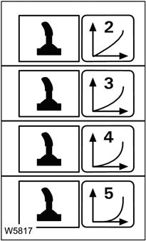
•Progressive characteristic curves (2) to (5); the speed is kept lower in the front range of the movement than with characteristic curve (1) and increases only with larger movements.
The higher the number of the characteristic curve, the further the control lever must be moved to instigate a clear increase in speed.
Press the F3 button once.
A red bar (1) appears below the display. Set the required minimum degree of brightness with the adjustment knob.
The brightness of the display changes during the setting procedure and you can view the set value (0 to 100%) on the display (1).
The degree of brightness which you set here is the minimum value for the automatic regulation.
There is no automatic regulation if you set 100%, the displays will be set at maximum brightness.
You can cancel the entry at any time using the Esc button. The settings are then reset.
To accept your setting, press the Enter button once. The red bar below the display goes out. The brightness is automatically regulated between the newly set value and 100%.
4 Telescope emergency program, F4
5Lamp test, F5
In the event of a malfunction in the telescoping mechanism, you can retract the main boom with the Telescope Emergency Program. Refer to Telescope Emergency Program, page 3-147 for more information
NOTE: The emergency program is not intended for crane operation and is therefore restricted to about 360 seconds.
To access the telescope emergency program:
•Press and hold the right dead man's switch
•Press the F4 button once: the display changes so you can enter the emergency keycode (3)
•Press the buttons (1) in the order:
Babc
•The symbols shown (4) confirm the entry.
If your input was incorrect, all the symbols (4) go out and you need to repeat the input.

You can cancel the entry at any time using the Esc button (5).
After correct input, the symbol (6) is displayed, the Telescope Emergency Program starts.
• Press the Esc button (5) to open the Main Menu and press the Telescope button F5 once.
The Telescoping submenu opens. Go to Telescope Emergency Program, page 3-147 for in-depth instructions.
When the ignition is turned on certain lamps light up to verify they are working.
To check those lamps while the ignition is already on:
Press and hold the F5 button. The lamps light up until you let go of the button.
For more information refer to, Lamp Test, page 3-58.
The operating hours are displayed below the symbols, e.g. 1,680 hours and 12 minutes for the telescoping mechanism (3).
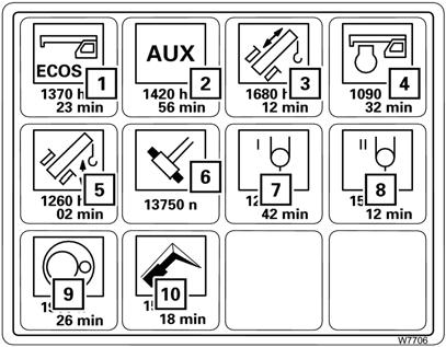
Exception: The value below symbol (6) indicates how often the Telescopic Section Lock has been operated, e.g. 13,750 times.
(1) ECOS
(2) Auxiliary systems: Counterweight cylinders
Crane cab cylinder
(3) Telescoping mechanism
(4) Engine operation
(5) Lift cylinder
(6) Telescope locking system
(7) Main hoist
(8) Auxiliary hoist
(9) Swing gear
(10) Boom extension
Refer to Operating Hours, page 3-59 for more information on this submenu.
The critical load control prevents the engine from stalling at high power requirements.
ECOS registers the currently available motor output and the hydraulic performance currently required by the power units.
If the required hydraulic performance is above the current motor output (e.g. when conducting an additional crane movement), the critical load control automatically reduces the hydraulic performance of the power units.
The swing gear is not influenced by the critical load control.
The critical load control is switched on together with the ignition. You should only switch off the critical load control if it is faulty (engine stalls or individual power units can no longer be controlled).
• Switching off: press button F7 until the dot turns black
• Switching on: press F7 button (1) until the dot (2) turns green.
If the telescope status is no longer displayed you must enter the current telescope values from the RCL display. The display (6) shows the values for telescopic sections 1 to 5.
To enter set values:
Press one of the buttons (1) to (5), the values in the display (6) turn yellow. Each time you press a button, the corresponding value in the display (6) switches continuously between the fixed lengths and the symbol (7) for unlocked.

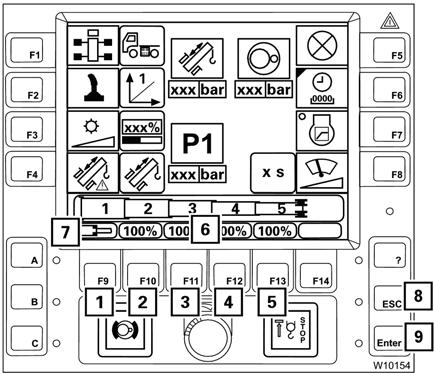
Enter the desired set values for all telescopic sections from the RCL. You can cancel the entry at any time using the Esc button (8).
To confirm the entered values, press the Enter button (9) once.
You must now accept the values, refer to Entering the Current Telescope Status, page 3-60 for more information.
Current pressure in bar for the telescope cylinder (10).
Current pressure in bar for the slewing gear (11).
Current pressure in bar (12) for movements of the following:
•Hoists
•Lift cylinder
•Counterweight cylinders
•Incline cab
•Locking units
Adjusting the Brightness of the Display
The brightness of the displays is regulated automatically by the ECOS, depending on the ambient brightness. You can set a minimum degree of brightness manually, which is always observed when the brightness is regulated.
1. If necessary, open the main menu (Esc) and press the F4 button (1) (Figure3-49) once. The Settings submenu opens (Figure3-50).
2. Press the F3 button (1) once (Figure3-50).
A red bar will appear below the percent display.
3. Set the required minimum degree of brightness with the adjustment knob (2).
The brightness of the display changes during the setting procedure and you can view the set value (0 to 100%) on the display. The degree of brightness which you set here is the minimum value for the automatic regulation.
NOTE: There is no automatic regulation if you set 100%. The displays are always displayed with maximum brightness.
You can cancel the input at any time by pressing the Esc button. The settings are then reset.
4. To accept the entered minimum brightness, press the Enter button.
The red bar below the display goes out. The brightness is automatically regulated between the newly set value and 100%.
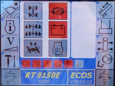
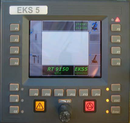
Lamp Test
Warning
Loss of Control Hazard!
Always perform the following lamp tests and immediately replace faulty lamps or have them replaced! Serious injury or property damage may result.
After the ignition has been switched on, a lamp test is conducted.
Check that the lamps indicated in Figure3-51 and Figure3-52 light up briefly.
If the specified time is insuff icient, switch on the ignition again.
Contact Crane Care if one or more lamps do not light up. If the specified time is insufficient, you can carry out the lamp test again as follows:
1. If necessary, in the ECOS display, open the main menu and press the F4 button (1) (Figure3-53) once.
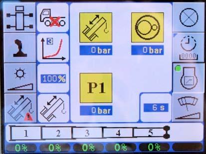
The Settings submenu opens.
2. Press the F5 button (1) (Figure3-54).
The lamps indicated in Figure3-51 and Figure3-52 light up until you let go of the button.
If necessary, you can set the minimum brightness of the display, refer to Adjusting the Brightness of the Display, page 3-57.