46 minute read
RT9150E OPERATOR MANUALOPERATING CONTROLS AND PROCEDURES


Traveling — Being Towed/Pulled
Manitowoc recommends connecting to a pintle hook (if equipped) or evenly attaching to the tie-down lugs when being towed by another vehicle.,
Caution
Machine Damage Hazard!
It is recommended to attach cables/straps to the optional pintle hook (if equipped) or evenly attach to the tie-down lugs if being towed by another vehicle.
Should the crane become mired down, use a tow truck or tractor to free the vehicle. Severe damage to the drivetrain may occur if the operator attempts to free the crane unassisted.
• Ensure the boom is in a horizontal position and not elevated above 0°.
• Ensure the outrigger beams and jacks are fully retracted with the floats properly stowed.
Caution
Machine Damage Hazard!
It is recommended to attach cables/straps to the pintle hook if one is available or evenly attach to the tie-down lugs if being towed by another vehicle.
Should the crane become mired down, use a tow truck or tractor to free the vehicle. Severe damage to the drivetrain may occur if the operator attempts to free the crane unassisted.
To avoid severe damage to the drive train while the crane engine is disabled:
• Disconnect drivelines.
• Disengage parking brake by manually turning parking brake adjustment until axle turns free.
Danger
Run-away Crane Hazard!
Disabling the parking brake may result in the crane rolling away freely without the ability of the operator to stop the crane.
Ensure wheel chocks are properly placed when parking crane with the parking brake disabled.
Death or serious injury and damage to machinery could result from moving machinery.
• Secure steering to prevent turning while towing.
• Conduct all travel with the assistance of a ground person to warn the operator of any changing conditions in the terrain being traversed.
Traveling with Boom Extension and/or Insert Erected
Caution
Traveling is not permitted with a boom extension reeved with two parts of line.
Damage to the boom extension may occur.
36 ft
(11 m)/59 ft (18 m) Extension
Travel is permissible under the following conditions:
• The boom extension shall be erected at minimum offset. If traveling with just the 36 ft (11 m) extension, the stinger extension must be stowed on the side of the main boom, not on the 36 ft folding extension.
• Jobsite travel only on firm, level surface.
• Main boom shall be fully retracted.
• Main boom angle: 0 degrees minimum, 30 degrees maximum.
• Maximum travel speed: 2.5 mph (4 km/h).
• Counterweight shall be installed.
• The boom shall be over the front.
• Swing lock and pin shall be engaged.
• Hookblock must be removed from main boom nose.
• Headache ball may be reeved over boom extension, hanging 3 ft (0.9 m) below sheave.
59 ft (18 m) Extension Plus 26 ft (8 m)/ 19 ft (6 m) Extension Inserts
Travel is permissible under the following conditions:
• The boom extension plus inserts shall be erected at minimum offset.
• Jobsite travel only on firm, level surface.
• Main boom shall be fully retracted.
• Main boom angle: 0 degrees minimum, 40 degrees maximum.
• Maximum travel speed: 2.5 mph (4 km/h).
• Counterweight shall be installed.
• The boom shall be over the front.
• Swing lock and pin shall be engaged.
• Hookblock must be removed from main boom nose.
• Headache ball may be reeved over boom extension, hanging 3 ft (0.9 m) below sheave.
12 ft (3.6 m) Extension
Travel is permissible under the following conditions:
• The boom extension shall be erected at minimum offset.
• Jobsite travel only on firm, level surface.
• Main boom shall be fully retracted.
• Main boom angle: 0 degrees minimum, 20 degrees maximum.
• Maximum travel speed: 2.5 mph (4 km/h).
• Counterweight shall be installed.
• The boom shall be over the front.
• Swing lock and pin shall be engaged.
• Hookblock or headache ball may be reeved over boom extension, hanging 3 ft (0.9 m) below sheave.
Extended Travel
Caution
Tire Damage!
For extended travel, check the cold tire pressure prior to start. (Refer to tire inflation chart in load chart book.) After every one hour of travel time, regardless of ambient temperature, stop and allow the tires to cool off for at least 30 minutes. At the destination, the tires must be allowed to cool to ambient temperature before lifting on rubber.
Depending upon the tire manufacturer, the higher inflation pressures normally specified for lifting on rubber are not recommended for site to site transfer over extended distances. The higher static/creep 5 mph (8 km/h) inflation pressures may remain in the tire while operating the crane on site within a distance of less than 4miles (6.4 km).
Moving the Crane
The following superstructure conditions should be strictly adhered to before moving the crane. Procedures for accomplishing the following can be found in the various sections of this manual.
1. Fully retract the boom.
2. Ensure the swingaway jib is properly stowed and secured.
3. Swing the boom to over-the-front and lower it to slightly above horizontal.
4. Turn the Swing Brake switch on the front console to ON and engage the swing lock pin by turning the handle.
5. Actuate the Crane Function switch to prevent unintended operation of crane functions.
6. Remove the hook block and/or headache ball from the hoist cable(s) and stow securely before traveling or make sure the hook block or headache ball is properly secured to the tie down provided for that purpose.
7. Fully retract the outrigger jacks and remove the floats.
8. Properly store the floats.
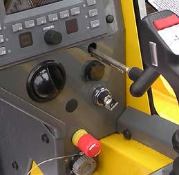
Steering
Steering is accomplished by the steering wheel and the rear steer control. These controls, used singly or together, provide front wheel steering, rear wheel steering, four-wheel steering, and crabbing capabilities (Figure3-109).
Front Wheel Steering
Conventional front wheel steering is accomplished with the steering wheel. This method of steering should always be used when traveling at higher speeds.
Warning
Operate the rear steer only for added job site maneuverability.
Rear Wheel Steering
Rear wheel steering is controlled by the REAR STEER control switch. Moving this switch to the desired position activates the rear steer cylinders, thereby steering the crane in the selected direction.
Four Wheel Steering
Four wheel steering is accomplished with the steering wheel and the REAR STEER control. Depending upon which direction the operator wishes to travel, the steering wheel is turned opposite direction of the REAR STEER control position. This allows the crane to turn or maneuver in close, restricted areas.
Crabbing
Crabbing is accomplished with the steering wheel and the REAR STEER control switch. Depending upon which direction the operator wishes to travel (crab), the steering wheel is turned in the same direction as the REAR STEER control switch. This permits driving the crane forward or backward in a crabbing manner.
Secondary Steering (CE Units)
A secondary steering system is provided to back up the normal front steering system if loss of hydraulic flow occurs. This happens automatically when normal steering load sense flow is lost. The pilot operated, two position, 3-way valve will shift and supply flow from the accumulator to the steer control valve to allow the operator to safely steer the crane to a safe stop.
The LOW STEER PRESSURE (PRESS) indicator comes on during pressure drops. This indicates the secondary steering system should also be working.
Traveling - Forward
Caution
Engage the swing lock pin for extended travel.
1. Actuate the Crane Function switch to prevent unintended operation of the crane functions.
2. After the engine has warmed up, apply the service brake and place the transmission shift lever from neutral (N) to forward (F) position.
3. Place the DRIVE AXLE switch to either 2WD or 4WD.
Caution
Use four wheel drive only when more traction is required. With the standard counterweight (39,000 lb (17690 kg)) installed, the maximum travel speed is 10 mph (16 kph). If the heavy counterweight (63,000 lb (28576 kg)) is installed, the maximum travel speed is 2.5 mph (4 kph), in first gear only.
NOTE: If hydraulic pressure is low, the parking brake cannot be released.
4. Put the transmission shift lever knob to the first (1) gear position and release the parking brake. Depress the foot throttle until maximum first gear speed is attained and shift into the second (2) gear position by rotating the handle.
5. Repeat the above procedure for the third (3) gear position and so forth until the desired travel speed is attained.
Caution
Do not downshift to a lower gear if the road speed is greater than the maximum speed of the lower gear.
Traveling - Reverse
Traveling in reverse is accomplished the same way as traveling forward, except for shifting the transmission shift lever to reverse (R) position and rotating the knob to the 1, 2, and 3 positions. (Refer to Traveling - Forward, page 3-113.)
Caution
Apply service brakes and bring crane to a complete stop before shifting transmission into reverse.
Four-Wheel Drive Operation
Caution
Machine Damage Hazard!
Do not tow or pull in 1st gear with Drive Axle Selector Switch in two-wheel drive position. Severe damage to the drive train will result. Always engage four-wheel drive.
If more traction is required due to slipping or spinning wheels, engage front axle drive as follows:
Caution
Possible Machine Damage!
Before shifting from two-wheel drive to four-wheel drive (or from four back to two), crane travel must be stopped.
1. Stop crane by depressing the Service Brake Foot Pedal.
2. Position Transmission Shift Lever to neutral (N) position.
3. Position Drive Axle Selector Switch to four-wheel low. NOTE: If Drive Axle Selector Switch is positioned to fourwheel low and the Service Brake Foot Pedal is not depressed or Transmission Shift Lever is not in neutral (N) position, the Four-Wheel Drive Indicator will flash and four-wheel drive function will not engage.
4. Select gear speed and direction of travel using the Transmission Shift Lever and Knob.
5. Drive crane as described under Traveling - Forward, page 3-113.
6. Return Drive Axle Selector Switch to the two-wheel high position as soon as two-wheel traction will suffice and crane motion has stopped. The Service Brake Foot Pedal must be depressed and Transmission Shift Lever must be in the neutral (N) position to shift from fourwheel low to two-wheel high
Travel On Slopes
Travel On Slopes with or without Standard Counterweight (39,000 lb (17690 kg)) installed
Observe the following when operating a crane on a slope:
• The slope; side to side or fore and aft, must not exceed 15% (8.5 degrees).
• Travel must be on an improved surface or on hardpacked dry earth having a minimum 0.5 coefficient of adhesion.
• Travel must be limited to a forward direction only.
• Travel must be limited to 4 wheel drive second gear.
• All boom sections must be fully retracted.
• The boom extension must be in the stowed position or removed from the crane.
• The boom must be lowered to horizontal and positioned over the front of the crane.
• The swing brake and turntable lock pin must be engaged.
• The hook block may be reeved over the main boom nose; the overhaul ball may be reeved over the main boom nose or auxiliary boom nose. Each must be secured at the tiedown on the carrier to prevent swinging.
• Tires must be inflated to the recommended pressure for pick and carry operations.
• The hydraulic tank must be filled to the specified level. The fuel tank must be over half full.
• No loads may be supported by the boom (such as no pick and carry loads) while traveling on a slope.
• All cribbing and other nonstandard accessories must be removed from the crane.
• Avoid holes, rocks, extremely soft surfaces, and other obstacles that might subject the crane to undue stresses and possible overturning.
• Travel must be conducted with the assistance of a ground person to warn the operator of any changing conditions of the terrain being traversed.
• While traveling on slopes in excess of 10% in 4 wheel drive first gear, it is possible that the engine may be able to drive through the crane service brakes. If this occurs, it is recommended to shift the transmission into a second gear.
Travel On Slopes with Optional Heavy Counterweight (63,000 lb (28576 kg)) installed
Observe the following when operating a crane on a slope with the heavy counterweight installed:
• The slope; side to side or fore and aft, must not exceed 10% (5.7 degrees).
• Travel must be on an improved surface or on hardpacked dry earth having a minimum 0.5 coefficient of adhesion.
• Travel must be limited to a forward direction only.
• Travel must be limited to 4 wheel drive first gear.
• All boom sections must be fully retracted.
• The boom extension must be in the stowed position or removed from the crane.
• The boom must be lowered to horizontal and positioned over the front of the crane.
• The swing brake and turntable lock pin must be engaged.
• The hook block may be reeved over the main boom nose; the overhaul ball may be reeved over the main boom nose or auxiliary boom nose. Each must be secured at the tiedown on the carrier to prevent swinging.
• Tires must be inflated to the recommended pressure for pick and carry operations.
• The hydraulic tank must be filled to the specified level. The fuel tank must be over half full.
• No loads may be supported by the boom (such as no pick and carry loads) while traveling on a slope.
• All cribbing and other nonstandard accessories must be removed from the crane.
• Avoid holes, rocks, extremely soft surfaces, and other obstacles that might subject the crane to undue stresses and possible overturning.
• Travel must be conducted with the assistance of a ground person to warn the operator of any changing conditions of the terrain being traversed.
Proper Operation of Differential Lock
Warning
Vehicle Control Hazard!
When using the differential lock, steering characteristics may be affected.
Try to use four wheel drive to gain adequate traction before using the differential lock.
Do not operate the differential lock while the crane is moving; when traveling downhill, at speeds above 10 mph, on hard, dry surfaces or during axle spin.
Failure to follow these warnin gs may result in loss of vehicle control causing serious injury or death.
NOTE: The differential lock will not operate unless the DRIVE selector switch is in the 4WD-LO position.
General
The purpose of the differential lock is to provide maximum traction and control on poor road or highway surfaces. When the differential locks are actuated, the clutch collar completely locks the differential case, gearing, and axle shafts together, thus maximizing traction to both wheels of each axle. The lock position will also protect against spinout. When normal driving conditions exist (during periods of good traction), the differential locks should not be actuated. The axles should be allowed to op erate with differential action between both wheels.
When using the differential locks, the operator must remember the following:
1. The AXLE DIFF control switch is a momentary rocker switch and must be held in the LOCK position.
2. The differentials can be locked or unlocked when the vehicle is standing still or at a constant low speed when the wheels are not slipping.
3. Lock differentials and operate vehicle only at low speeds.
4. When the differentials are locked, the crane’s turning radius will increase, creating an understeer condition. The operator must use caution, good judgement and drive at low speeds when operating the vehicle with locked differentials.
NOTE: Turning on hard surfaces with locked differentials should be avoided.
5. Lock the differentials only when maximum traction is needed on poor road or highway surfaces.
6. Always unlock the differentials when the need for maximum traction has passed or when traveling on good road or highway surfaces.
7. Do not lock the differentials when the wheels are slipping. Damage to the differentials can result.
8. Do not lock the differentials when the vehicle is traveling down steep grades and traction is minimal. Potential loss of vehicle stability can result.
Operation
The differential lock (AXLE DIFF) should preferably be engaged when the crane is STATIONARY but may be engaged when moving if the following conditions are met.
1. The crane is moving very slowly (creep speed).
2. The wheels are not spinning at the time of engagement. When traveling with the lock engaged do not deviate from a straight path more than is absolutely necessary.
1. When operating the differential lock, place switch to the locked position with crane stationary or at slow speed.
2. If moving at slow speed, let up momentarily on the accelerator to relieve torque on the differential gearing. This will fully engage the differential locks. When activated the square amber LED on the switch should be illuminated.
3. Proceed over the poor road condition cautiously. When adverse condition has passed, do the following:
1. Place the differential lock (AXLE DIFF) switch to the UNLOCK position while maintaining slow speed.
2. Let up momentarily on accelerator to relieve torque on differential gearing, allowing differential to fully unlock. The square amber LED on the switch should go out.
3. Resume driving at a normal speed using good driving judgement.
Proper Operation of Axle Oscillation Lockouts
NOTE: The following procedure should be used to periodically check the axle oscillation system and ensure that it is in proper working condition.
1. Ensure the tires are inflated to the recommended pressure. Refer to the Load Chart Book in the crane cab for proper inflation pressures.
2. With the hook unloaded, the boom fully retracted and centered over the front at no more than a 10 to 15 degree boom angle, place the crane on a block or curb so that one rear tire is approximately 15 to 30 cm (6 to 12 inches) above the level of the opposite tire.
3. Slowly swing the superstructure to the right or left until the axle oscillation lockout valve is activated. This will lock the rear axle out of level. Do not swing beyond the tire track.
4. After engaging the swing brake, slowly drive off of the block or curb and stop. The rear tires should both be touching the road surface and the opposite front tire should be light or slightly off the road surface.
5. Release the swing brake and swing the superstructure until it is centered over the front.
Caution
Do not operate the crane if the axle oscillation lockout system is not functioning properly.
6. If the axle oscillation lockout valve is not functioning properly, the crane will not re-level itself. If the rear axle does not lock or unlock properly, evaluate the lockout system and repair as necessary.
General Crane Operation Pump Drive
The main hydraulic pumps are mounted on the torque converter drive pad. The hydraulic oil cooler pump is mounted on the engine. The pumps operate any time the engine is running.
Operating the Crane On Outriggers
In order to operate the crane on outriggers:
• the transmission must be shifted into 4WD (four-wheeldrive) for the outriggers to be deployed and
• the parking brake set.
When this procedure is correctly followed, the wheels will not rotate with the crane on outriggers during any crane function.
Control Lever Operation
The control lever operation for all crane functions is standard, i.e. the closer the lever is to neutral (center), the slower the system responds. The control lever should be returned to neutral to hold the load. Never feather the hoist control lever to hold the load.
NOTE: Always operate the control levers with slow, even pressure.
Preload Check
After the crane has been readied for service, an operational check of all crane functions (with no load applied) should be performed. The Preload Check is as follows:
Caution
Operate engine at or near governed rpm during preload check of crane functions.
NOTE: Carefully read and become familiar with all crane operating instructions before attempting a preload check or operating the crane under load.
1. Extend and set outriggers.
2. Raise, lower, and swing the boom a minimum of 45° right and left.
3. Telescope the boom in and out.
4. Raise and lower the cable a few times at various boom lengths. Ensure there is no kinking.
Using Your Load Chart
NOTE: One of the most important tools of every Grove crane is the load chart found in the crane operator’s cab. Terms to know are shown in (Figure3-110).
The load chart contains a large amount of information, which must be thoroughly understood by the operator.
The load chart contains outrigger capacity charts for fully extended, mid extended, outriggers for the main boom and boom extension, and fully retracted outrigger beams for main boom only. In addition, the load chart contains two on-rubber capacity charts: 360° stationary, and pick and carry over front.
The capacity charts are divided into structural strength and stability limits. This is shown by the bold line across the chart. Capacities above the line are structural strength limits and capacities below the line are stability limits.
The left column is the load radius, which is the distance from the center of crane rotation to the load center of gravity. The top row lists various boom lengths ranging from fully retracted to fully extended or boom extension lengths and offsets. The number at the intersection of the left column and top row is the total load capacity for that load radius and boom length or boom extension lengths offset. The number in parentheses below the total load capacity is the required boom angle (in degrees) for that load. Any boom length between increments should always be treated as if it was the next longer length. For example, if the actual boom length is 50 ft and the chart shows boom lengths of 48 and 54 ft, use the load capacity shown in the 54 ft column.
Another important section is the range diagram. The range diagram shows the operating radius and tip height that can be achieved at a given boom length and angle. If the operator knows the radius and tip height required for a specific lift, the angle and boom length can be quickly determined from the range diagram. Or, if the boom length and angle are known, the tip height and operating radius can be quickly determined.
A lifting diagram is included to describe over side, over rear, and over front lifting areas. The lifting area diagram shows that the locations of the outrigger jack cylinders in the fully extended position are used to mark the boundaries of the lifting areas.
A boom extension capacity chart and notes are included to list the capacities for the extension length, load radius, and boom angle.
Another section contains the notes for lifting capacities. Be sure to read and understand all the notes concerning lifting capacities.
The load chart also gives weight reductions for Grove load handling devices such as hook blocks, headache balls, boom extensions, etc., which must be taken into consideration as part of the load. Remember, the weight of any other load handling devices such as chains, slings, or spreader bars must be added to the weight of the load.
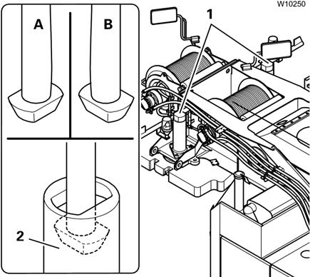
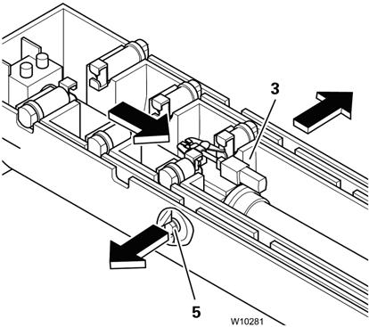
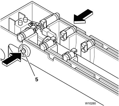
Counterweight Installation/Removal
Refer to Figure3-111.
Danger
Crushing Hazard!
Ensure no one is on the counterweight platform while the counterweight is being lifted or lowered. Before lifting or lowering the counterweight, ensure there are no objects on top of or below it.
Serious injury or death may result if these warnings are not followed.
- extended and retracted and
- turned to the positions
Unlocked (A) or Locked (B).
To lift and lower the counterweight, the lifting cylinders have to be locked in the counterweight tubes (2).
The lifting cylinders (1) can be:
FIGURE3-111
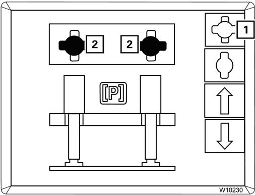
To operate the counterweight hoist unit, you must open the Counterweight submenu:
1. If necessary, open the main menu, press Esc button.
2. In the Main menu, press the F6 button (1) (Figure3-112) once.
The Counterweight submenu opens.
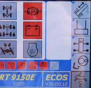
NOTE: If an error symbol (1) (Figure3-113) is displayed during subsequent operation, please contact Crane Care.
The extension or retraction of the lifting cylinders will only take place when both lifting cylinders are fully in the locked or unlocked positions.
Extending the Lifting Cylinders
Extension is only enabled when the superstructure is in the 180°, boom over-the-rear position.
Caution
Equipment Damage Hazard!
The hoist unit can become damaged by moving the lifting cylinders against the counterweight in the locked position.
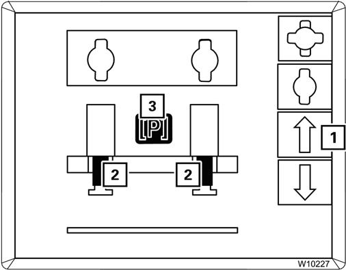
FIGURE3-114
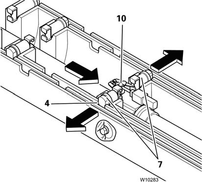
If the lifting cylinders (1) (Figure3-114) are to move into the cutouts, then the lifting cylinders have to be in the unlocked (2) position.
If the lifting cylinders are in the locked (3) position, then you may have to lift the counterweight off the counterweight platform and:
• extend the lifting cylinders,
• turn the lifting cylinders into the unlocked (2) position, refer to Locking/Unlocking Counterweight Lift Cylinders, page 3-119,
• retract the lifting cylinders.
To extend the lifting cylinders:
1. Press the F8 button (1, Figure3-115).
2. The lifting cylinders (2) extend: Yellow: Intermediate position Green: Extended.
The counterweight is now lowered, provided it has been rigged.
3. The display (3) turns red.
Retracting the Lifting Cylinders
To retract the lifting cylinders:
1. Press the F7 button (1) (Figure3-116).
2. The lifting cylinders (2) retract. Yellow: Intermediate position Green: Retracted
3. Press and hold the F7 button (1) until the Pre-tension Counterweight display (3) turns green
The counterweight which is needed for crane operation will now be pulled under the turntable with pressure.
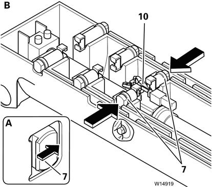
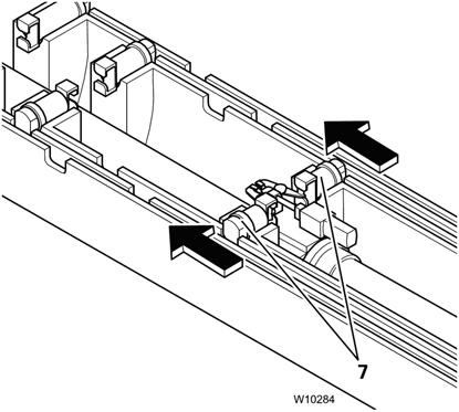
Locking/Unlocking Counterweight Lift Cylinders
The movement between the positions locked and unlocked will only be active when the lifting cylinders have been extended.
To rotate lifting cylinders to locked (Figure3-117):
1. Press the button (1).
2. The lifting cylinders (2) turn: Yellow: Intermediate position Green: Locked been pretensioned the locking cylinders need to engage the counterweight to secure it to the crane.
To rotate lifting cylinders to unlocked (Figure3-118):
1. Press the button (1).
2. The lifting cylinders (2) turn: Yellow: Intermediate position Red: Unlocked.
Locking/Unlocking the Counterweight
The counterweight is secured to the crane with a pair of horizontal locking cylinders. After the counterweight has
Locking the Counterweight
After pretensioning the counterweight:
1. Press the engage button (1) (Figure3-119). When the lock cylinders are fully engaged the lock cylinders icon (2) turns green.
Unlocking the Counterweight
In order to remove the counterweight the locking cylinders must be retracted:
1. Press the retract button (3) (Figure3-119). When the lock cylinders are fully retracted the lock cylinders icon (2) turns red.
Crane Functions
Operation of the Rated Capacity Limiter (RCL)
If the current rigging mode of the crane is registered properly, the RCL prevents the permissible lifting capacity from being exceeded and the crane from being overloaded.
Danger
Tipping Hazard!
If the actual rigging mode varies from the displayed rigging mode, the maximum load displayed by the RCL will not correspond to the permissible lifting capacity allowed in the Load Chart. Inaccurate programming of the RCL allows the crane to be improperly operated. You may only override the RCL if it becomes absolutely necessary in the event of an emergency. This is to put the crane into a safe condition in the event of a malfunction. In this case, do not perform any movements that would increase the load moment.
Serious injury or death may occur if the crane is overloaded or overturns.
The current rigging mode is based on measured values and manually entered values:
Registered Based on Measured Values
Registered Based on Manually Entered Values
Main boom lengthCounterweight
Main boom angleLength of boom extension
Current loadAngle of the boom extension
Luffing jib angleReeving
During the operation of the crane, a visual and acoustic early warning is issued before the load limit is reached and the functions are shut down that would lead into the overload range.
Switching on the RCL
NOTE: The RCL is not switched off if you turn the ignition key to position R instead of position 0 to restart the engine. The test program will not run and you will not have to acknowledge the settings again.
The RCL is switched on together with the ignition.
A test program runs after switching on the ignition. A continuous buzzer tone sounds for about 2 seconds and a lamp test is performed:
• Check whether you can hear a buzzer tone.
• Check that the lamps indicated in Figure3-120 light up briefly after turning on the ignition.
If the specified time is insufficient, switch on the ignition again or conduct a lamp test, refer to Lamp Test, page 3-58.
Contact Crane Care if one or more lamps do not light up.
WARNING
If the lamps or the buzzer fail, notify Crane Care and have the error rectified.
In the meantime, pay particular attention to the lamps in the event of a failure of the buzzer and vice versa.
After the test program the two lamps (1) light up and all power units are disabled.
What is displayed depends on whether the RCL had been switched off for up to 48 hours or had been switched off for more than 48 hours, refer to the following sections.
After Crane Shutdown of up to 48 Hours
Refer to RCL Monitoring submenu, Figure3-121.
After Crane Shutdown of more than 48 Hours
Refer to Figure3-122.
The RCL Monitoring submenu opens if the crane was shutdown for less than 48 hours.
The last set rigging mode is displayed, and the symbols (1) and (2) are green and flash.
You can accept the displayed values if they correspond to the actual rigging of the crane:
• Press the Enter button (3) once, the symbols (1) and (2) stop flashing.
• The lamps (4) and (5) go out. The RCL code is accepted.
If no error message is displayed, the RCL is set for crane operation and the crane functions are enabled.
Any pending errors are indicated on the display (6), refer to Error Messages in the Monitoring Submenu, page 3-91.
You must re-enter the current rigging if the displayed values do not correspond to the actual rigging mode of the crane, refer to Entering the Rigging Mode, page 3-81.
If the crane was shutdown for more than 48 hours the Enter Rigging Mode submenu opens:
• The SLI code 1100 (2) is displayed along with the corresponding rigging mode,
• The last reeving entered (1) is displayed.
You must now enter the actual rigging, refer to Entering the Rigging Mode, page 3-81.
Prior to Crane Operation
NOTE: Crane functions are only enabled when the RCL Monitoring submenu is open, refer to RCL Monitoring Submenu, page 3-86.
After Crane Shutdown of less than 48 hours the Monitoring submenu opens automatically.
After Crane Shutdown of more than 48 hours and after accepting a rigging mode—refer to Approve the Rigging Mode, page 3-84—the Monitoring submenu opens automatically.
Opening the Submenu Manually
Refer to Figure3-123.
You can also open the submenu manually:
1. If necessary, open the Main menu by pressing the Esc button until the Main menu opens.
2. Press the F8 button (1) once.
The Monitoring submenu opens.
NOTE: You can only quit the RCL Monitoring submenu when all crane movements have stopped; the control lever must be in the zero position.
Verify Rigging
Check whether the actual rigging of the crane corresponds to the displayed rigging mode.
Danger
Tipping Hazard!
Serious injury or death may occur if the crane is overloaded or overturns.
If the actual rigging mode varies from the displayed rigging mode, the maximum load displayed by the RCL will not correspond to the permissible lifting capacity allowed in the Load Chart. Inaccurate programming of the RCL allows the crane to be improperly operated.
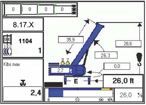
In the RCL Monitoring submenu (Figure3-124) verify the following items correspond to the actual rigging of the crane:
If you need to correct the values, press the Esc button to open the Rigging Mode submenu, refer to Entering the Rigging Mode, page 3-81.
You can start working with the crane when the current rigging mode of the crane is displayed correctly.
Verify Hoists Display
Refer to Figure3-123.
(1) The angle of the rigged luffing boom extension.
(2) The length of the rigged boom extension.
(3) The number of reeved rope lines.
(4) The hoist that is switched on, refer to Verify Hoists Display, page 3-123.
(5) The rigged counterweight.
The lamp that lights up must always be for the actual hoist with which the load is to be lifted:
• Lamp I: Must light up if the load is to be raised with the main hoist.
• Lamp II: Must light up if the load is to be raised with the auxiliary hoist.
To switch the display to the hoist that will be used, refer to the following section.
How to Switch the Hoist Display
In the following example the main hoist will be selected:
3. The lamps I and II go out.
Deploying the Outriggers
DANGER Tipping Hazard!
4. Switch on the main hoist by pressing the switch once.
Now lamp I for the main hoist is ON and the ECOS indicator is green.
DANGER Tipping Hazard!
After switching over the hoists, always check whether the displayed reeving value corresponds to the current reeving value of the displayed hoist and, if necessary, enter the current reeving value. This will prevent the RCL from making calculations based on an incorrect reeving value and the crane from becoming overloaded or from overturning.
Verify Reeving
After selecting the hoist and making sure the associated lamp is on verify that the reeving for that hoist is correct.
The indicator (3) (Figure3-124) will show the last entered reeving value for the main hoist.
If no reeving has been entered yet, the RCL selects 1 for the reeving.
If necessary, enter the current reeving, refer to Entering the Reeving, page 3-83.
All four outrigger beams must be equally extended to the mid-position vertical stripe with the lock pins engaged or fully extended or retracted before beginning operation. The operator must select the proper load chart and RCL program for the outrigger position selected.
Serious injury or death may occur if the proper load chart and RCL program are not used and the crane tips over.
1. Engage the parking brake using switch on the steering column, see Park Brake Switch, page 3-5.
2. Enable the four-wheel drive system using switch on the steering column, see Drive Select Switch, page 3-5.
3. Position the outrigger floats directly out from each outrigger to where the outriggers will be properly extended.
4. Press the appropriate button on the outrigger menu and hold to extend. The chosen outrigger beam(s) should begin to extend. (Refer to Engaging the Mid-Extend Lock Pin, page 3-125 if the crane is to be operated with the outriggers at the mid-extend position.) Extend each outrigger in turn. Refer to Outrigger Monitoring System (OMS) RCL Display (Optional—Standard in North America), page 3-125
NOTE: More than one outrigger at a time may be extended. However, to ensure that each outrigger is fully extended, repeat step 4 for each outrigger after a multi-outrigger extension.
5. After all four outrigger beams have been fully extended, press the appropriate button on the outrigger menu for extending the desired jack and hold the button to extend. Extend each jack, positioning the float as necessary, until the locking levers of the float engage the jack cylinder rod. Verify each float is secure on its related jack cylinder rod.
NOTE: More than one jack may be extended at one time.
6. With each jack float firmly touching the ground, extend the front jacks approximately 3 to 4 in (8 to 10 cm).
7. Extend the rear jacks approximately 3 to 4 in (8 to 10 cm).
8. Repeat steps 6 and 7 until all wheels are clear of the ground and the crane is level as indicated by the bubble level indicator on the right side control panel, see Level Indicator, page 3-8.
NOTE: If it is suspected that the bubble level indicator is out of adjustment, refer to the Service Manual for the proper procedure to check and adjust the indicator.
Engaging the Mid-Extend Lock Pin
1. Turn the locking pin 90° from its stowed position and allow the pin to rest on top of the outrigger beam.
NOTE: It may be necessary to use the appropriate outrigger extension button and jog the outriggers slightly to ensure proper pin engagement.
2. Slowly extend or retract the outrigger beam, allowing the locking pin to drop into the hole in the top of the outrigger beam, engaging the outrigger beam at the desired length.
Stowing the Mid-Extend Lock Pin
1. Retract the outrigger jack cylinder.
NOTE: If the lock pin is wedged in the hole in the outrigger beam, it may be necessary to jog the button while pulling upward on the pin.
2. Lift the lock pin and turn it 90° to its stowed position.
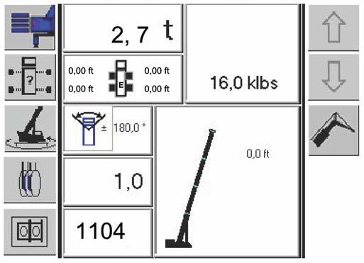
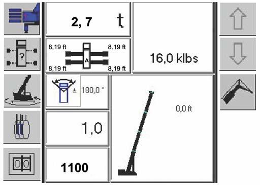
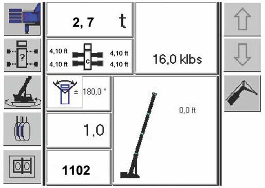
Outrigger Monitoring System (OMS) RCL Display (Optional—Standard in North America)
DANGER Tipping Hazard!
The crane can overturn, causing death or serious injury or sustain serious damage from operating the crane from outrigger positions other than fully retracted, midextended or fully extended.
The OMS is an operator’s aid only, it does not program the RCL. The operator must select the proper rigging code.
The Outrigger Monitoring System (OMS) aids the operator by automatically identifying the horizontal position of each outrigger beam. The OMS uses eight sensors, two per outrigger beam, to identify when an outrigger beam is positioned to one of three pre-defined locations, including retracted, mid-extend, and full extend.
Set up of the outriggers is the same for cranes equipped with OMS; refer to Outriggers Submenu, page 3-27. The RCL only indicates the horizontal position of the outrigger beam and should not be used to deploy the beam.
When an outrigger is not properly deployed the outrigger symbol will flash and the operator will need to properly deploy the outriggers for the rigging code selected.
NOTE: If an outrigger symbol and its associated distance number does not display then that sensor is not properly calibrated or has failed.
Fully Retracted or 0% Deployed
With all outriggers fully retracted and corresponding rigging code selected, the outrigger symbol (1, Figure3-126) should stay lit when all outriggers are at the correct position.
When an outrigger beam is not within the ±3% tolerance from the selected rigging setup the outrigger symbol will flash and display the actual outrigger length (1, Figure3-127).
By pressing the “ENTER” key twice the operator will confirm the rigging code. Should an outrigger be outside the ±3% tolerance an error code will display, refer to Error Code Display, page 3-126 and (1) Figure3-132.
Mid-Extended or 50% Deployed
With all outriggers 50% deployed and corresponding rigging code selected, the outrigger symbol (1, Figure3-128) should stay lit if all outriggers are at the correct position.
When an outrigger beam is not within the ±3% tolerance from the selected rigging setup the outrigger symbol will flash and display the actual outrigger length (1, Figure3-129).
When an outrigger beam is not within the ±3% tolerance from the selected rigging setup the outrigger symbol will flash and display the actual outrigger length (1, Figure3-131).
By pressing the “ENTER” key twice the operator will confirm the rigging code. Should an outrigger be outside the ±3% tolerance an error code will display, refer to Error Code Display, page 3-126 and (1) Figure3-132.
Fully Extended or 100% Deployed
With all outriggers 100% deployed and corresponding rigging code selected, the outrigger symbol (1, Figure3-130) should stay lit when all outriggers are at the correct position.
By pressing the “ENTER” key twice the operator will confirm the rigging code. Should an outrigger be outside the ±3% tolerance an error code will display, refer to Error Code Display, page 3-126 and (1) Figure3-132.
Error Code Display
When any outrigger is not at the correct position matching the selected rigging code, the confirmation of the rigging code will still be available; however, the corresponding error code will be displayed on the operating screen (1, Figure3-132).
An error code of 8.17.2 is when an outrigger is at a lesser predefined location, 0% or 50%, when it should be at 50% or 100%, respectively. For example, error 8.17.2 will be displayed if one or more outriggers are at 0% or 50% when selecting 100%.
An error code of 8.17.3 is when an outrigger is more than ±3% of 0%, 50% or 100%, or if a sensor is disconnected or has failed.
The audible alarm can be silenced by pressing the “CE” key, but the out of tolerance condition still exists.
ECOS Error Reporting
There are two errors that can be reported in the ECOS display associated with the OMS:
• 9.2.1.7; length sensor disconnected or broken cable.
• 9.2.1.14; sensor not calibrated, or sensor output below minimum or above maximum.
Stowing the Outriggers
1. Pre-select the rear outriggers with the appropriate switches. Press and hold the jack retract switch until the rear jacks have retracted several inches.
2. Pre-select the front outriggers with the appropriate switches. Press and hold the jack retract switch until the front jacks have retracted several inches.
3. Repeat steps 1 and 2 until the crane is resting on all four wheels and the jack floats are several inches off the ground.
Caution
Falling Equipment Hazard!
Keep feet and hands clear of floats when unlocking the floats from the jacks.
Hands and/or feet could be injured by a falling float.
4. Release the locking levers and allow the floats to drop to the ground.
5. Continue to retract the jacks until they are fully retracted.
6. Pre-select the desired outrigger(s) with the appropriate switches. Press and hold the outrigger retract switch. The chosen outrigger beam should begin to retract. (Refer to Stowing the Mid-Extend Lock Pin, page 3-125 if the crane has been operated with the outriggers at the mid-extend position.) Retract each outrigger in turn.
NOTE: More than one outrigger may be retracted at one time.
Caution
Heavy Equipment Hazard!
Outrigger floats weigh 92 lb (41.7 kg), use care when lifting to prevent injury.
Hands and/or feet could be injured by a falling float.
7. After all outriggers have been fully retracted, stow the outrigger floats.
8. Pin the floats to their front and rear stowing points with retainer pins.
Rotating the Superstructure
Refer to Main Menu, page 3-21 and Swing Gear and Brake Submenu, page 3-30 for information on using the ECOS system.
Danger
Tipping Hazard!
Always check before rotating the superstructure whether it is permitted in the crane's current rigging mode (counterweight, outrigger span, working radius).
Before activating swing, sound the horn and verify that all personnel are clear of rotating and moving parts. Death or serious injury could result from being hit by the load or moving machinery.
Caution
Machine Damage Hazard!
Disengage the swing brake and the swing lock pin and/or 360° swing lock before attempting to swing.
Never push or pull the swing control lever through neutral to the opposite direction to stop swing motion. Use the swing brake foot pedal to stop swing rotation.
Do not accelerate the slewing speed to such a degree that the load starts swinging.
Damage to the crane may result from improper swing operation.
NOTE: Automatic rear axle oscillation lockout will activate when the superstructure swings right or left of the 0° forward position.
Swing Operation Prerequisites
The following prerequisites must be fulfilled before rotating the superstructure:
• The Swing Lock is released.
• The counterweight lifting cylinders are fully retracted.
• Slewing is permissible with the current rigging mode, refer to Rotating Superstructure with Counterweight, page 3-129.
• The current rigging mode is entered on the RCL.
If slewing is not permissible with the current rigging mode, the slewing gear is disabled.
Rotating the Superstructure
To rotate the superstructure, use the controls on the left-hand armrest:
1. Push the top of the Swing Gear switch once.
2. ECOS indicator must be green.
NOTE: If an RCL code has been entered for the working position 180° to the rear or Free-on-wheels, an RCL shutdown will occur after switching on the swing gear, and rotation will be disabled. To acknowledge the shutdown, you must either switch off the swing gear or set down the load and enter an RCL code for the 360° working range.
3. Apply the swing foot brake or leave the control lever at the neutral position, depending on which control is selected in the Main menu.
4. Release the Swing Lock by pulling up on the lever.
5. Pull the Swing Lock Pin handle out to release the pin lock.
Published 2-18-2016, Control # 614-00 Grove
6. Engage the swing gear:
a.Brake pedal: Release the brake pedal as you move the control lever in the direction you want the superstructure to rotate.
b.Control lever: Move the control lever in the direction you want the superstructure to rotate. NOTE: With the Brake pedal function, swing movements are not braked automatically. If you let go of the control lever or move it to the neutral position, the swing movement will cont inue; use the brake pedal to stop the rotation.
Always operate the control lever with a slow, even pressure. Depending on your configuration; use the swing brake pedal or control lever to stop rotation, then push the Swing Brake switch once, the icon will turn red, to engage the swing brake preventing further rotation.
Rotating Superstructure with Counterweight
Tipping Hazard!
The RCL only disables the swing operation if the RCL code was entered correctly and the RCL is not overridden.
Therefore always check before rotating whether the RCL code is valid for the current rigging mode displayed. This prevents swing operations from being allowed within impermissible ranges and the crane from overturning.
You may only rotate the superstructure with a rigged counterweight if the crane is supported by a sufficient outrigger span and the permi ssible working radii are observed. Otherwise the crane will overturn during rotation. The current rigging mode is registered by the RCL code entered, and the RCL disables the swing operation if it is not permitted.
The following table specifies (depending on the counterweight and outrigger span) whether rotating the superstructure is:
• Permitted; limited to working radii on Load Chart
• Disabled.
Elevating/Lowering the Boom
1. Push the top of the Boom Lift switch once.
Danger
Crushing and/or Tipping Hazard!
Keep the area above and below the boom clear of all obstructions and personnel when elevating the boom. Long cantilever booms can create a tipping condition, even when unloaded and in an extended, lowered position.
Death or serious injury could result from the crane tipping over and/or being crushed by moving machinery.
Refer to Main Menu, page 3-21 for information on using the ECOS system.
Depending on the size of the load and the rigging mode, the RCL switches off the lowering process of the boom as soon as the working area specified in the Load Chart is left.
To lower the boom out of the working range, refer to Lowering the Boom to a Horizontal Position, page 3-131.
NOTE: The lift cylinder is not intended for lifting loads. If an overly heavy load is lifted by raising, the SLI switches this process off.
Boom Elevating/Lowering Operation
WARNING
Unexpected Operation Hazard!
When using a multi-function control lever, always verify that the proper function is selected before you move the control lever.
This way, you avoid accidents due to unexpected crane movements.
To elevate/lower the boom, use the controls on the righthand armrest:
2. The ECOS lift cylinder indicator turns green.
If the telescope function was selected; that indicator turns red.
3. Use the right-hand joystick controller:
To raise the boom: Push the control lever to the left.
To lower the boom: Push the control lever to the right.
Caution
Machine Damage Hazard!
When lowering the boom, simultaneously let out the hoist cable to prevent two-blocking the boom nose and hook block.
4. You can regulate the elevate/lower speed by:
- moving the control lever
- changing the engine speed with the accelerator
- limiting the speed by setting the maximum speed in the Power Unit Speed submenu, see Power Unit Speed Submenu, page 3-48.
- using the High Speed function, refer to High Speed Main and Auxiliary Hoist Boost Button, page 3-12.
NOTE: The maximum lift cylinder speed is automatically reduced as the boom length is increased. If you now reduce the working radius (e.g. by retracting the boom), the lift cylinder speed is automatically increased again.
You can adjust the sensitivity of the control levers to suit the operating conditions, refer to Settings Submenu, page 3-52.
5. After the elevate/lower operation is complete be sure to press the Boom Lift switch again or select the Crane Function switch to turn the function off to avoid unintentional use.
Lowering the Boom to a Horizontal Position
Warning
Tipping Hazard!
Do not under any circumstances override the RCL. If the RCL shuts down the lowering procedure, the crane is in a condition in which the main boom may not be lowered beyond the working range (e.g. the load or working radius is too large).
The crane will overturn if you continue to lower the boom with the RCL overridden.
Serious injury or death may result if the crane overturns.
Lowering the boom out of the working range is enabled only without a load and if there is a rigging table for the current rigging mode.
Enabling is automatic, the rigging tables cannot be entered manually. The same tables apply to raising outside of the working range.
The RCL switches off the lowering procedure at about 10 to 15° if there are no rigging tables for the current rigging mode. In this case, you must bring the crane into a rigging mode for which a rigging table exists (e.g. retracting, setting down the load, other superstructure position).
All rigging modes for which rigging tables exist can be found in the Load Chart.
Lowering Boom to Horizontal with Boom Extension Installed
If the following requirements are met, lowering into the horizontal position with boom extension with a swing range of 360° is permitted and is monitored by the RCL.
The following requirements must be satisfied when raising and lowering the main boom with rigged boom extension:
• The current rigging mode with the rigged boom extension is entered on the RCL, and the corresponding RCL code is displayed as per the Load Chart.
• The current reeving on the boom extension is entered for the hoist whose rope is reeved on the boom extension.
• Apart from the overhaul ball, there is no load on the boom extension.
• The main boom is fully retracted.
The RCL will only allow the main boom to raising and lowering when the main boom is completely retracted.
When all of the above requirements have been satisfied, the RCL will automatically switch to the rigging tables and lowering the boom can then be done in the angle range below the working range of approximately 15°.
Tilting the Crane Cab
Caution
Falling Objects Hazard!
Close the cab door before tilting and remove all loose objects (e.g. bottles) from the cab.
In this way, you prevent objects from tipping over, the cab door opening by itself, and unintended operational accidents caused by falling objects.
NOTE: Park brake must be engaged to operate the cab tilt feature and cab must be completely down (at zero level) for the drive functions to be enabled.
The crane cab can be tilted to the rear in order to attain a better operating position when working at great heights, refer to Cab Tilt Switch, page 3-13.
To Raise the Cab
1. Close the crane cab door.
2. Press the top of the switch (1) (Figure3-133).
To Lower the Cab
1. Close the crane cab door.
2. Press the bottom of the switch (1).
The crane cab continues to tilt as long as you hold the button down or the end position is reached.
Telescoping the Boom
For a review of the mechanics involved in extending and retracting the boom, refer to Telescope System Overview, page 3-133. Refer to Main Menu, page 3-21 and Telescope Submenu, page 3-32 for information on using the ECOS system.
Telescope Mechanism
The telescoping process requires locking and unlocking of the telescope cylinder assembly with the sections of the main boom. You can telescope the main boom in two ways:
•Manual Telescoping, refer to Manual Telescoping, page 3-138
For manual telescoping, you must initiate all locking and unlocking processes at the right time.
•Telescoping with Teleautomation, refer to Telescoping with Teleautomation, page 3-135
When telescoping with teleautomation, you enter the telescoping requirements and the ECOS system controls all the locking and unlocking processes automatically. You may additionally need to telescope to an intermediate length manually.
Fixed Length, Intermediate Length, Telescoping
Length
There are Load Chart tables for main boom fixed lengths, main boom intermediate lengths and main boom telescoping lengths.
The lengths are automatically detected by the RCL, and the corresponding lifting capacities according to the Load Chart tables are enabled and displayed automatically.
•Main Boom Fixed Length
Main boom fixed lengths have the greatest lifting capacities. A main boom fixed length is reached if:
- All telescopic sections are locked to a fixed length and,
- All telescopic sections are engaged with the locking pin notch.
•Main Boom Intermediate Length
A main boom intermediate length is reached if all telescopic sections are not locked to fixed lengths.
- Extend the main boom to the required length before hoisting the load!
- You cannot telescope the boom with the specified lifting capacities for main boom intermediate lengths.
•Main Boom Telescoping Length
The main boom is at a telescoping length if it is extended to an intermediate length and may be telescoped with the current load. The size of the load that can be telescoped depends on the angle of inclination and on the degree of lubrication of the main boom.
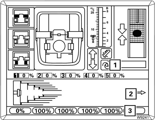
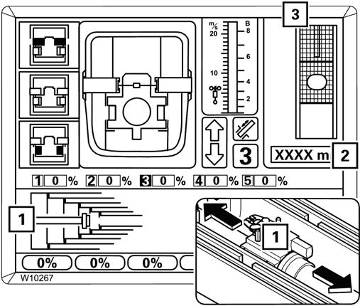
Current Telescope Display, (Figure3-134)
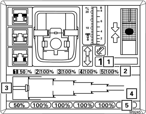
FIGURE3-134
The displays (1) to (5) show the current telescoping of the telescopic sections 1 to 5 in percent, e.g. 50%.
Fixed and intermediate lengths differ in the locking pins (6):
•Green: Fixed length
•Black: Intermediate length
•Flashing: Telescopic section at fixed length with the locking pin not engaged to the section or unlocked
Telescope System Overview
Refer to Figure3-135.
The illustration shows the main boom assembly with the telescope cylinder completely retracted into the main boom base section (9) and the first three telescopic sections 1 to 3 (1) to (3).
Telescoping Process
The following section describes the normal operation of the telescoping process from its initial starting point. The telescoping processes consist of 4 steps:
Each telescopic section is equipped with two section locking pins (7) which are extended by spring force and retracted by the butterfly levers (10).
A telescopic section is locked when the locking pins (7) in that section engage the cutouts (4) in the previous section.
The telescope cylinder piston rod (8) is attached to the boom base (9). When hydraulic pressure is applied to the cylinder the rod remains stationary and the cylinder extends.
The telescope cylinder has two locking pins (5) at the bottom, which engage the section to be moved and the butterfly mechanism at the top (10) to retract the section locking pins.
After the telescope cylinder is positioned at a locking point:
• The cylinder locking pins (5) extend into the cutouts (6) in the section to be moved, the telescope cylinder is now locked.
• The butterfly mechanism (10) engages the section locking pins (7) and retracts them, the telescopic section is now unlocked.
• The cylinder can now be extended/retracted, moving the section it is locked to.
For a more in-depth description of the telescoping process refer to the next section.
1. Unlocking the telescoping cylinder (Figure3-136); a. The cylinder locking pins (5) retract, unlocking the telescope cylinder.
2. Moving and locking the telescope cylinder (Figure3-137); a. The telescope cylinder moves into the telescopic section to be telescoped, e.g. section 3 (3). b. The cylinder locking pins (5) extend, the telescope cylinder is locked into section 3.
Published 2-18-2016, Control # 614-00
3. Unlocking the telescopic section (Figure3-138); a. The telescope cylinder extends until the notch in the section locking pins (7) are no longer engaged with the section (A). b. The butterfly mechanism (10) retracts the section locking pins (7) unlocking the telescopic section.
4. Moving, locking and engaging the telescopic section (Figure3-139); a. The telescope cylinder pushes the telescopic section to a new locking point. b. The section locking pins (7) extend into the cutouts (4). c. The telescopic cylinder retracts until the section locking pins’ notch (7) is engaged with the telescopic section (1).
The weight of the load is now on the telescopic sections and not on the telescoping cylinder.
Telescoping with Teleautomation
When telescoping with teleautomation, you enter the desired fixed lengths and then move the control lever in the required direction. Switching between the telescopic sections is carried out automatically by ECOS.
NOTE: If the desired telescoping is not a fixed length, you can first telescope to the next closest fixed length with the teleautomation and then telescope further to the desired length manually.
Switch the telescoping mechanism on and open the Telescope submenu, refer to Telescope Submenu, page 332.
To Switch on Input Mode
The display (6) (Figure3-141) shows the set values for all telescopic sections.
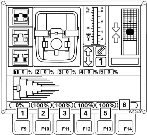

The values are displayed in red if teleautomation is switched off.
No values are shown if teleautomation is disabled.
1. To turn on input mode, press one of the F9 to F13 buttons (1) to (5).
The values in the display (6) turn yellow.
Input mode is now switched on.
You can exit the input mode with the Esc button. The values in the display (6) turn red.
To Enter Values
Refer to Figure3-142.
1. Press one of the F9 to F13 buttons (1) to (5). Each time you press a button, the corresponding value in the display (7) switches continuously between the fixed lengths.
2. Enter the desired set values for all telescopic sections, e.g. 0%, 100%, 100%, 100%, 100%.
3. Press the button Enter once. The entered set values are confirmed.
If the entered set values are not permissible, the values on the display (3) (Figure3-143) turn red. Teleautomation remains switched off.
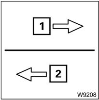
• The arrow (1) (Figure3-144) for the indicated telescoping direction flashes if you move the control lever in the wrong direction.
• If you move the control lever in the correct direction, ECOS telescopes the boom automatically until the direction has to be changed. Then the arrow (2) for the new telescoping direction is indicated, e.g. for Retracting.
If the entered set values are permissible, the values on the display (3) turn green.
• The symbol (1) is displayed and the teleautomation is switched on.
• The display (2) shows the telescoping direction for the teleautomation start, e.g. the arrow pointing to the right, for Extending.
Telescope Operation
Move the control lever for the displayed telescoping direction.
• In the case of the telescope cylinder only moving (without telescopic section), both arrows are displayed. Cylinder only movements are automatically performed in both directions, irrespective of the control lever movement.
You can regulate the speed for telescoping in the same way as for manual telescoping.
The telescoping process stops when the entered set values are reached.
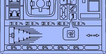
• Move the control lever to the zero position. The display (Figure3-146) changes from the teleautomation icon (1) to the section number icon (2). Teleautomation is switched off.
Canceling Teleautomation
Refer to Figure3-147.
FIGURE3-147
To cancel teleautomation, press one of the F1 to F3 buttons (1), (2) or (3) once.
The telescoping process is stopped:
• The display (5) goes out,
• the icon (4) appears,
• the values in the display (6) are red.
Teleautomation is now switched off.
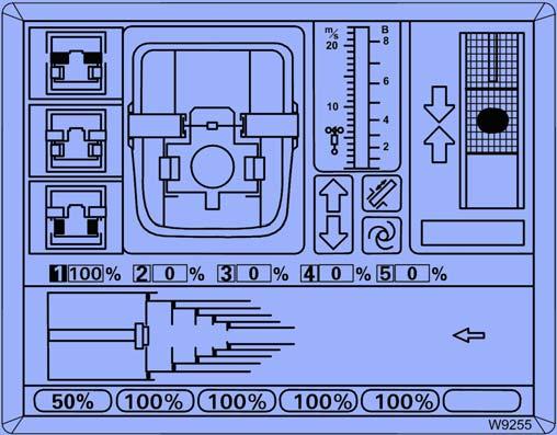
Example of Telescoping with Teleautomation
Refer to Figure3-148.
Assuming the current telescoping is 100/0/0/0/0 and the telescoping cylinder is locked in telescopic section 1(1).
The desired telescope status is 50/100/100/100/100 (2).
The display should correspond to Figure3-148 once you have entered the desired telescope status and confirmed it.
ECOS calculates the following telescoping sequence:
Telescopic section 1retractto 0%
Telescopic section 5extendto 100%
Telescopic section 4extendto 100%
Telescopic section 3extendto 100%
Telescopic section 2extendto 100%
Telescopic section 1extendto 50%
Since the first step is retracting, the arrow (3) points to the left.
1. Move the control lever for retracting and hold it there, refer to (Figure3-149).
Telescopic section 1 is fully retracted. The following processes are carried out automatically, in order:
- Telescopic section 1 retracts; display (3) 0%
- Telescopic section 1 locks; pins (5) green
- Telescope cylinder unlocks; pins (4) red
- The telescope cylinder moves into telescopic section 5; display (2)
- Telescope cylinder locks; pins (4) green
The arrow (1) shows the new telescoping direction, extending.
NOTE: The arrow (1) flashes as long as you are moving the control lever for retracting.
2. Move the control lever for extending and hold it there.
Manual Telescoping
To telescope manually, you must initiate all locking and unlocking processes, which are then carried out automatically.
The following sections describe the operating procedures necessary to extend/retract the boom manually.
NOTE: The operating order depends on the current initial position. For an overview of the telescope process, refer to Telescope System Overview, page 3-133.
• Checking the Initial Position, page 3-138
• unlocking the telescoping cylinder,
• moving the telescoping cylinder (without telescopic section),
• locking the telescoping cylinder,
• unlocking the telescopic section,
• telescoping the telescopic section,
ECOS now automatically moves telescopic sections 5, 4, 3 and 2 to the full extent and stops when telescopic section 1 reaches the set value of 50%.
3. Move the control lever to the zero position.
- The display (4) goes out.
- The display (1) is active again.
- The values in the display (5) are red.
- The display (2) shows the current telescoping, e.g. 50/100/100/100/100.
- The display (3) shows the current telescoping graphically.
Teleautomation is switched off.
NOTE: To extend telescopic section 1 to 60%, for example, you can now further extend this telescopic section manually.
• locking the telescopic section.
NOTE: The lengths given in the following illustrations are purely sample values, and may therefore deviate from the actual values displayed.
Checking the Initial Position
Before telescoping, you must check the following statuses:
• The Current Telescope Status, page 3-139,
• the Position of the Telescope Cylinder, page 3-139,
• the Position of the Locking Pins, page 3-139.
If necessary, open the main menu by pressing the Esc button, then press the F5 button (1) once (Figure3-151).
The Telescoping submenu opens.
If an “error” display (1) (Figure3-152) is pending, all operating elements are disabled, refer to Telescope Mechanism Error Messages, page 3-37
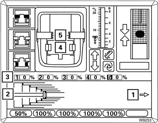
Current Telescope Status
Refer to Figure3-153.
The display (2) shows the current telescoping in percent for each telescopic section.
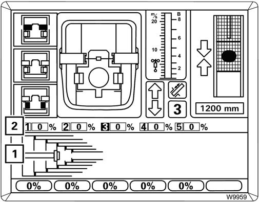
The display (1) shows the current telescope diagram.
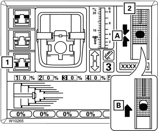
Position of the Telescope Cylinder
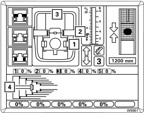
Refer to Figure3-154.
The display (4) shows how far the telescope cylinder is extended, e.g. 1,200 mm (3.93 ft).
If the telescope cylinder is near a locking point:
• The display (3) shows the corresponding telescopic section, e.g. telescopic section 3,
• the display (2) shows the corresponding telescopic section number in green,
• the display (5) shows one or two arrows, depending on the distance to the locking point.
The display (1) shows a top view of the current position.
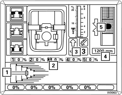
Position of the Locking Pins
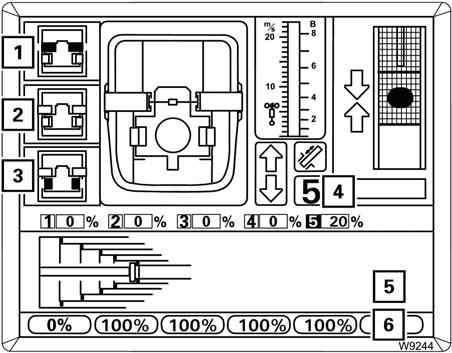
Refer to Figure3-155.
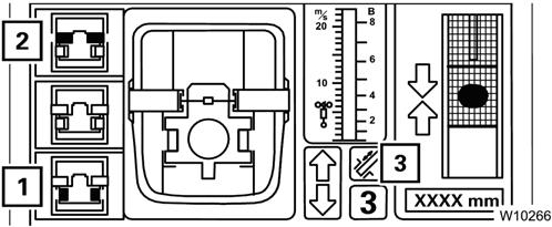
The display (3) shows the current positions of the locking pins:
(1) the telescope cylinder pins,
(2) the telescopic section pins.
The current status of the pins are indicated by color: Red: Unlocked Green: Locked
Yellow: Intermediate position.
The display (4) shows the same positions as detailed in Figure3-156:
• (1) Locking pins on the telescope cylinder
• (2) Locking pins on the telescopic sections Green: Locked
No display: Unlocked or intermediate position.
Unlocking the Telescope Cylinder
Unlocking the telescope cylinder is required for the cylinder to be moved separately without telescopic section.
NOTE: The telescope cylinder and the telescopic section cannot be unlocked simultaneously.
Prerequisites
Refer to Figure3-157.
The following conditions must be met to unlock the telescope cylinder:
• The telescoping mechanism must be on, symbol (2) green,
• the telescope cylinder must be locked, symbol (1) grey.
To Select Unlock
Refer to Figure3-158.
Press the F3 button (1) once.
• If the telescopic section is locked, symbol (1) flashes indicating the telescope cylinder can be unlocked with the control lever.
• If the telescopic section is unlocked, symbol (2) flashes indicating that when the control lever is actuated the telescopic section will lock and the telescope cylinder will unlock.
NOTE: In the next step, both selections are carried out one directly after the other.
Unlocking the Telescoping Cylinder
Refer to Figure3-159.
Move the right control lever for telescoping.
If required, the section locking pins (2) will extend first. The cylinder locking pins (3) will retract: Yellow: Intermediate position, Red: Unlocked.
In the unlocked position, the symbol (1) is yellow.
If the control lever is moved, the telescope cylinder moves immediately.
Extending/ Retracting the Telescope Cylinder
Operating the telescope cylinder (without telescopic section) is required when the telescope cylinder needs to be moved into a different telescopic section.
Prerequisites
Refer to Figure3-161.
If the symbol (1) (Figure3-160) is still flashing after approximately 10 seconds, this means that the locking pins are under load.
Let go of the control lever.
The display (2) shows which direction you need to move the cylinder to take the load off:
(A) Retract
(B) Extend.
Caution
Boom Damage Hazard!
Repeated attempts to extend and retract may cause damage to the boom system.
NOTE: If removing the load does not cause unlocking, you must lock the telescope cylinder and restart the unlocking process, refer to Lock Telescope Cylinder, page 3-142.
In order to extend/retract the telescope cylinder the following conditions must be met:
• The telescoping mechanism must be on, symbol (3) green
• The telescopic section must be locked, symbol (2) grey
• The telescope cylinder must be unlocked, symbol (1) yellow.
Extend/Retract
Refer to Figure3-162.
Move the control lever in the desired direction to extend or retract the telescope cylinder (1).
The display (2) shows the currently extended length, e.g. 1,500 mm (4.92 ft).