57 minute read
OPERATOR


At wind speeds greater than 13.4m/s, it is not permissible to lift a load greater than 12,040kg, even if the wind resistance area of the load is less than 14.45m2
Refer to the information from the above crane configuration, examine several load conditions.
Load example 1.1:
With known Wind Drag Coefficient of the load Cd, and
• load to be lifted of 11,200kg,
• Projected Wind Area Ap = 9.20m2 ,
• Wind Drag Coefficient Cd = 1.5 wind resistance area of load can be estimated as Awr(load) = Ap x Cd = 9.2 x 1.5 = 13.8m2
Refer to the above Lifting Limits at wind speed V(z) >13.4m/s and ≤ to 20.1m/s. Comparing the load and wind resistant area to the allowable:
• Is the load to be lifted less than allowable load? 11,200 kg ≤ 12,040 kg YES
• Is Awr(load) less than Awr(allow) ? 13.8 m2 ≤ 14.45m2 YES
Conclusion: This load is permissible to lift in wind speed up to 20.1m/s.
Load example 1.2:
With unknown Wind Drag Coefficient of the load Cd,
• Load to be lifted of 10,000 kg,
• Projected Wind Area Ap = 5.45 m2,
• Wind Drag Coefficient Cd = unknown
NOTE: If exact Wind Drag Coefficient is not known, it shall be assumed as 2.4.
• the wind resistance area of load can be estimated as Awr(load) = Ap x Cd = 5.45x2.4 = 13.08m2
Refer to the above Lifting Limits at V(z) > 13.4 m/s and ≤ 20.1 m/s. Comparing the load and wind resistant area to the allowable:
• Is the load to be lifted less than allowable load?
10,000 kg ≤ 12,040kg YES
• Is Awr(load) less than Awr(allow) ?
13.08 m2 ≤ 14.45m2 YES
Conclusion: This load is permissible to lift in wind speed up to 20.1m/s.
Load example 1.3a:
With large wind resistance area of the load Awr(load),
• Load to be lifted of 14,000 kg,
• Projected Wind Area Ap = 21.85 m2 ,
• Wind Drag Coefficient Cd = 1.2 the wind resistance area of load can be estimated as: Awr(load) = Ap X Cd = 21.85 x 1.2 = 26.22 m2
Refer to the above Lifting Limits at wind speedV(z)>13.4 m/s and ≤ 20.1 m/s. Comparing the load to the allowable:
• Is the load to be lifted less than allowable load?
14,000 kg ≤ 12,040 kg NO
Conclusion : This load is NOT permissible to lift in wind speed up to 20.1m/s.
Refer to the above Lifting Limits at wind speedV(z)<3.4 m/s. Comparing the load to the allowable:
• Is the load to be lifted less than allowable load? 14,000 kg ≤ 15,050kg
The maximum permissible wind speed for this load is 13.4m/s, depending on the wind resistance area of the load.
• Is Awr(load) less than Awr(allow)? 26.22 m2 ≤ 18.06 m2
Conclusion : This load is NOT permissible to lift in wind speed at 13.4m/s, but is permitted to lift at a reduced wind speed calculated as follows:
Ratio = 1.45
From Table 2-5, the maximum permissible wind speed at ratio of 1.45 (rounded to next higher table value of 1.6) is 10.6m/s.
Conclusion: This load is permissible to lift in wind speed up to 10.6m/s only.
Load example 1.3b:
With large wind resistance area of the load Awr(load) ,
• Load to be lifted of 8,000 kg,
• Projected Wind Area Ap = 15.25 m2,
• Wind Drag Coefficient Cd = 1.3 the wind resistance area of load can be estimated as Awr(load) = Ap x Cd = 15.25x1.3 = 19.83 m2
Refer to the above Lifting Limits at wind speed V(z) >13.4 m/s and ≤ 20.1 m/s . Comparing the load and wind resistant area to the allowable:
• Is the load to be lifted less than allowable load?
8,000 kg ≤ 12,040 kg YES
• Is Awr(load) less than Awr(allow)?
19.83 m2 ≤ 14.45 m2 NO
Conclusion : This load is NOT permissible to lift in wind speed up to 20.1m/s, but permitted to lift at a reduced wind speed calculated as follows:
Ratio = 1.37
From Table 2-5, the maximum permissible wind speed at ratio of 1.37 (rounded to next higher table value of 1.4) is 17.0m/s.
Conclusion: This load is permissible to lift in wind speed up to 17.0m/s only.
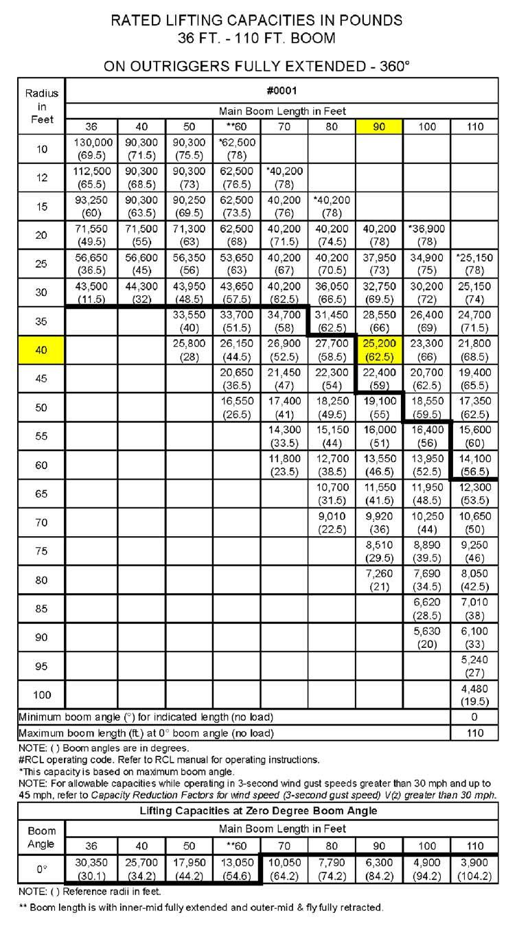
Rated Load Chart Example-Non-metric FIGURE2-4
Table 2-6Example-Capacity Reduction Factors for Wind Speed V(z) Greater than 30mph - Non-metric
(Only for lifting with main boom on fully extended outriggers, with or without stowed extension)
For wind speed Vz (3-second gust speed at boom tip height) is greater >30>mph ≤ 45mph, the Reduced Capacity shall be calculated by multiplying the Published Rated Capacity by the following factors:
Main Boom Length in Feet
Wind Speed Vz< 30mph < 45mph 364050607080 90100110
Factor0.90.90.80.80.80.8 0.80.70.5
Wind resistance area of load, Awr(load), shall not exceed maximum allowable wind resistance area Awr(allow)
Maximum allowable wind resistance area in[ft2],Awr (allow) =0.0059 x calculated reduced capacity in lb.
Wind resistance area of load, Awr(load) = projected wind area Ap x wind drag coefficient Cd for the load. For wind resistance area of load, Awr (load) > maximum allowable wind resistance, Awr (allow), refer to crane Operator Manual.
Table 2-7 Awr Ratio and Permissible Wind Speed V(z)- Non-Metric
Note: Permissible and rated wind speeds in this table are the 3-second gust wind speeds at boom tip height.
Ratio: 1.21.41.61.82
Maximum Permissible Wind Speed (mph)
Example and Sample Calculations (Non-metric)
The following example illustrates how to calculate allowable load while operating in wind speed (3-second wind gust speed) above 13.4 m/s (30 mph) and maximum permissible wind speeds with various combinations of lifted load and wind resistance area.
NOTE: Permissible and calculated wind speeds in this example are the 3-second wind gust speeds at boom tip height V(z)
Example 2:
A crane is configured with:
• boom length = 90 ft,
• load radius = 40 ft, and
• wind speed is measured at V(z) ≤ 45mph.
The Rated Load Chart Example-Non-metric (Figure2-4), at maximum permissible wind speed, V(z) = 30 mph, the rated lifting capacity m (allow) for this configuration is 25,200lb.
The maximum allowable wind resistance area of load is:
Awr(allow) =0.0059x m(load) (2.5)
Awr(allow) =0.0059x25,200=149ft2
Lifting Limits at wind speed V(z) < 30mph at this configuration:
• Maximum load 25,200lb
• Maximum wind resistance area of load 149ft2
For the allowable wind speed>30mph and ≤ 45mph, reduce the allowable load. , the Factor for a main boom length of 90ft is 0.8, thus the allowable load is: m(allow) =0.8x25,200=20,160lb
This reduced capacity load has an allowable wind resistance area of:
Awr(allow) =0.0059x20,160=119ft2
Lifting Limits at wind speed V(z)> 30mph and ≤ 45mph at this configuration:
• Maximum load 20,160lb
• Maximum wind resistance area of load 119ft2
Example, wind speeds greater than 13.4m/s is NOT permissible to lift a load greater than 20,160lb, even if the wind resistance area of the load is less than 119ft2 .
Refer to the above crane configuration for the following load conditions:
Load example 2.1:
With known Wind Drag Coefficient of the load Cd,
• load to be lifted of 19,500lb,
• Projected Wind Area Ap =70ft2 ,
• Wind Drag Coefficient Cd =1.5 then the wind resistance area of load can be estimated as Awr(load) = Ap x Cd = 70x1.5=105ft2
Refer to the above Lifting Limits at wind speed V(z) > 30 mph and ≤ 45 mph. Comparing the load and wind resistant area to the allowable:
• Is the load to be lifted less than allowable load?
19,500lb ≤ 20,160lb YES
• Is Awr(load) less than Awr(allow)? 105ft2 ≤ 119ft2 YES
Conclusion: This load is permissible to lift in wind speed up to 45 mph.
Load example 2.2:
With unknown Wind Drag Coefficient of the load Cd,
• Load to be lifted of 18,000lb,
• Projected Wind Area Ap = 45ft2,
• Wind Drag Coefficient Cd = unknown
NOTE: If exact Wind Drag Coefficient is not known, it shall be assumed as 2.4. the wind resistance area of load can be estimated as Awr(load) = Ap x Cd = 45x2.4=108ft2
Refer to the above Lifting Limits at wind speed V(z) >30mph and ≤ 45mph . Comparing the load and wind resistant area to the allowable:
• Is the load to be lifted less than allowable load?
18,000 lb ≤ 20,160 lb YES
• Is Awr(load) less than Awr(allow)? 108ft2 ≤ 119ft2 YES
Conclusion: This load is permissible to lift in wind speed up to 45mph.
Load example 2.3a:
With large wind resistance area of the load Awr(load),
• Load to be lifted of 22,000lb,
• Projected Wind Area Ap =180ft2 ,
• Wind Drag Coefficient Cd = 1.2 the wind resistance area of load can be estimated as:
Awr(load) = Ap x Cd = 180x1.2 = 216ft2
Refer to the above Lifting Limits at wind speed V(z) > 30mph and ≤ 45mph. Comparing the load to the allowable:
• Is the load to be lifted less than allowable load?
22,000lb ≤ 20,160lb NO
Conclusion : This load is NOT permissible to lift in wind speed up to 45mph.
Refer to the above Lifting Limits at wind speed V(z) up to 30mph. Comparing the load to the allowable: Is the load to be lifted less than allowable load?
22,000lb ≤ 25,200lb. . . . . . . . . .
The permissible wind speed for this load is 30mph, depending on the wind resistance area of the load.
• Is Awr(load) less than Awr(allow),?
216ft2 ≤ 149ft2 . . .
NO
Conclusion : This load is NOT permissible to lift in wind speed at 30mph, but permitted to lift at a reduced wind speed calculated as follows:
Ratio = 1.45
From Table 2-7, the maximum permissible wind speed at ratio of 1.45 (rounded to next higher table value of 1.6) is 23.7mph.
Conclusion: This load is permissible to lift in wind speed up to 23.7mph only.
Load example 2.3b:
With large wind resistance area of the load Awr(load),
• Load to be lifted of 12,000lb,
• Projected Wind Area Ap = 125ft2,
• Wind Drag Coefficient Cd = 1.3 the wind resistance area of load can be estimated as: Awr(load) = Ap x Cd =125x1.3=162ft2
Refer to the above Lifting Limits at wind speed V(z) >30mph and ≤ 45mph . Comparing the load and wind resistant area to the allowable:
• Is the load to be lifted less than allowable load?
12,000lb ≤ 20,160lb
• Is Awr(load) less than Awr(allow),?
162ft2 ≤ 119ft2
Conclusion : This load is NOT permissible to lift in wind speed up to 45mph, but permitted to lift at a reduced wind speed calculated as follows:
Ratio = 1.37
From Table Table 2-7, the maximum permissible wind speed at ratio of 1.37 (rounded to next higher table value of 1.4) is 38.0mph.
Conclusion: This load is permissible to lift in wind speed up to 38.0mph only.
Lifting Operations
Before lifting, position the crane on a firm surface, properly extend and set the outriggers, and level the crane. Depending on the nature of the supporting surface, adequate cribbing may be required to obtain a larger bearing surface.
The crane is equipped with a bubble level that should be used to determine whether the crane is level. The load line can also be used to estimate the levelness of the crane by checking to be sure it is in-line with the center of the boom at all points on the swing circle.
If the jib, or auxiliary boom nose is to be used, ensure the electrical cable and the weight for the Anti-Two-Block Switch are properly installed and the Rated Capacity Limiter (RCL) is programmed for the crane configuration. Refer to the RCL operator manual supplied with the crane.
Verify the crane’s capacity by checking the Load Chart against the weight of the load. Then, lift the load slightly at first to ensure stability before proceeding with the lift.
Be sure the load is properly rigged and attached. Always determine the weight of the load before you attempt to lift it and remember that all rigging (slings, etc.) and lifting devices (hook block, jib, etc.) must be considered part of the load.
Measure the load radius before making a lift and stay within approved lifting areas based on the range diagrams and working area diagrams on the crane’s Load Chart
Always keep the load as near to the crane and as close to the ground as possible.
Do not overload the crane by exceeding the capacities shown on the appropriate Load Chart . Death or serious injury could result from the crane tipping over or failing structurally from overload.
The crane can tip over or fail structurally if:
• The load and crane’s configuration is not within the capacity as shown on the applicable Load Chart and notes.
• The ground is soft and/or the surface conditions are poor.
• Outriggers are not properly extended and set. On models equipped with outriggers that can be pinned at the mid-extend position, the outriggers must also be pinned when operating from the mid-extend position.
• Cribbing under the outrigger pads is inadequate.
• The crane is improperly operated.
Do not rely on the crane’s tipping to determine your lifting capacity.
Be sure the hoist line is vertical before lifting. Do not subject the crane to side loading. A side load can tip the crane or cause it to fail structurally.
Load Chart capacities are based on freely suspended loads. Do not pull posts, pilings, or submerged articles. Be sure the load is not frozen or otherwise attached to the ground before lifting.
If you should encounter a tipping condition, immediately lower the load with the hoist line and retract or elevate the boom to decrease the load radius. Never lower or extend the boom; this will aggravate the condition.
Use tag lines whenever possible to help control the movement of the load.
When lifting loads, the crane will lean toward the boom and the load will swing out, increasing the load radius. Ensure the crane’s capacity is not exceeded when this occurs.
Do not strike any obstruction with the boom. If the boom should accidentally contact an object, stop immediately. Inspect the boom. Remove the crane from service if the boom is damaged.
Never push or pull with the crane boom.
Avoid sudden starts and stops when moving the load. The inertia and an increased load radius could tip the crane over or cause it to fail structurally.
Using only one hoist at a time when lifting loads is recommended. See “Tilt-Up Panel Lifting” on page 2-21 for additional lifting instructions.
Always use enough parts-of-line to accommodate the load to be lifted. Lifting with too few parts-of-line can result in failure of the hoist rope.
Counterweight
On cranes equipped with removable counterweights, ensure the appropriate counterweight sections are properly installed for the lift being considered.
Do not add material to the counterweight to increase capacity. United States Federal law prohibits modification or additions which affect the capacity or safe operation of the equipment without the manufacturer’s written approval. [29CFR 1926.1434]
Outrigger Lift Off
Regarding “lifting” of an outrigger pad during craning activities, be advised that the rated loads for these cranes, as indicated on the crane’s Load Chart, do not exceed 85% of the tipping load on outriggers as determined by SAE J765 OCT90 “Cranes Stability Test Code.” An outrigger pad may lift off the ground during operation of the crane within the capacity limits of the Load Chart, yet the crane will not have reached instability. The “balance point” for stability testing according to SAE and Manitowoc criteria is a condition of loading wherein the load moment acting to overturn the crane is equal to the maximum moment of the crane available to resist overturning. This balance point or point of instability for a crane does not depend on “lifting” of an outrigger but rather on comparison of the “opposing” load moments.
The occurrence of an outrigger lifting from the ground is often attributed to the natural flex in the crane’s frame. This may happen when lifting a load in certain configurations within the capacity limits of the Load Chart and is not necessarily an indication of an unstable condition.
Provided the crane is properly set up, the crane is in good working condition, that all operator’s aids are properly programmed, that the qualified crane operator adheres to the instructions found in the applicable Load Chart, Operator Manual and decals on the crane, the crane should not be unstable.
Multiple Crane Lifts
Multiple crane lifts are not recommended.
Any lift that requires more than one crane must be precisely planned and coordinated by a designated person. If it is necessary to perform a multi-crane lift, the operator shall be responsible for assuring that the following minimum safety precautions are taken:
• Secure the services of a designated person to direct the operation.
• Use one qualified signal person.
• Coordinate lifting plans with the operators, designated person, and signal person prior to beginning the lift.
• Maintain communication between all parties throughout the entire operation. If possible, provide approved radio equipment for voice communication between all parties engaged in the lift.
• Use outriggers on cranes so equipped.
• Calculate the amount of weight to be lifted by each crane and attach slings at the correct points for proper weight distribution.
• Ensure the load lines are directly over the attach points to avoid side loading and tr ansfer of loading from one crane to the other.
• Do not travel. Lift only from a stationary position.
Tilt-Up Panel Lifting
Requirements and recommendations regarding operation and use of Grove Cranes are stated on decals and in the Operator and Safety Handbook and other manuals provided with each specific model machine. Using the subject crane to perform tilt-up panel lifting with two hoist lines poses new and different hazards than does normal lifting use.
Therefore, the following additional precautions must be taken if it is necessary for the crane to be used to perform tiltup panel lifting using a crane equipped with two hoists:
• The crane must be set up and operated in accordance with Grove’s instructions in the Operator and Safety Handbook, Load Capacity Chart, and decals affixed to the crane.
• The hoist rope from the main hoist shall be reeved over the main boom nose reeved for two parts of line.
• The hoist rope from the auxiliary hoist shall be reeved over the auxiliary boom nose reeved for one part of line.
• The load shall be connected with the main hoist line connected to the end closest to crane and the auxiliary hoist line connected to the end farthest from the crane.
• The anti-two block system shall be installed and inspected to confirm that it is active to monitor both hoist lines.
• The RCL hoist selection shall be set to main hoist and two parts offline.
• The wire rope and sheaves shall be inspected prior to and following the lifting operations for chaffing or scrubbing.
• The total gross load shall not exceed 80% of the standard load chart. The operator shall be responsible to control this as the RCL does not have a feature to set reduced lifting limits.
• The auxiliary hoist line shall be considered part of the deducts to determine net allowable load.
• The panel shall be lifted so that the hoist lines are in line with the crane.
• The load shall be controlled to prevent rotation of the load and to ensure the load stays in line with the boom.
• The load must be balanced with the auxiliary: load line not taking more than half the load at any time during the lift. The RCL will not be providing coverage for the line pull of the auxiliary hoist line.
• The effect of wind loads on the crane and panel shall be taken into consideration. Operations shall be halted if the wind can cause a loss of control in handling the load.
• The main hoist line shall be used to raise the panel into the vertical position.
Ensure that all personnel working on and around the crane are properly trained and thoroughly familiar with operational functions of the crane and safe operating and work practices. Personnel should be thoroughly familiar with regulations and standards governing cranes and their operation. Work practices may vary slightly between government regulations, industry standards, local and job-site rules and employer policies so a thorough knowledge of and compliance with all relevant work rules is necessary.
Pile Driving And Extracting
Pile driving and extracting are applications approved by Manitowoc, provided all equipment is operated within factory guidelines. The following operating requirements must be used during pile driving and extracting with a Manitowoc mobile hydraulic crane:
Pile driving and pile extraction using a mobile crane introduces many variable and unknown factors that must be considered when using a crane for this application. Because of these factors, discretion must be exercised when pile driving or pile extraction is being considered.
It is not the intention of Manitowoc to recommend specific types or makes of pile driving and pile extraction equipment, but rather to advise of the operational requirements to help avoid the detrimental effects that pile driving and pile extraction can have on the crane.
In addition to the operating requirements that are detailed in the operating manuals and on the load capacity chart, pile driving and extracting operations are approved by Manitowoc, provided all guidelines outlined below are followed:
• All pile driving and extracting operations shall be restricted to fully extended outriggers with all tires clear of the ground.
• The combined weight of the driver or extractor, piling, leads, attachments, etc., shall not exceed 80% of the published load chart values for on-outriggers operation.
• The pile driver or pile extractor and attachments shall be kept clear of the boom nose at all times.
• The pile driver and piling shall be suspended from a hoist cable with sufficient line speed to meet or exceed the rate of descent of the driver and piling to preclude impact loading or vibration from being induced into the boom and crane structure.
• Pile driving or extracting shall be restricted to over the main boom only and shall not be permitted over a jib.
• Pile extraction using only the crane’s hoist line is unsafe and not permitted since load values cannot be accurately determined. Only pile extraction devices that do not transmit vibration or shock loading into the crane are permitted. All possible precautionary measures shall be taken to prevent shock loads or vibration from being imposed on crane components, either directly through the hoist cable or indirectly from ground borne vibration.
• The load lines shall be kept vertical at all times during pile driving and pile extraction operations.
• The operator and other personnel associated with the pile driving and pile extraction operation shall have read and understood all safety standards applicable to crane operations as well as being thoroughly trained in the safe operation of pile driving and extracting equipment.
Crane Equipment
• Hoists shall be equipped with a cable follower to aid in proper spooling of cable.
• All cable retainer pins and cable guides/retainers shall be in place.
• All jibs must be removed from the machine before pile driving or extraction begins.
• All hoist hooks shall be equipped with a positive locking latch.
Crane Inspection
• In addition to the crane's frequent and periodic inspections, dated daily records shall be maintained showing inspections were performed on the crane during the time it was used for pile driving or extraction.
• All anti-two block warning devices and RCL systems shall be inspected daily and verified to be functional.
• All areas of the crane subject to fatigue shall be inspected monthly, and before the crane is to return to lifting service.
• The boom shall be inspected daily to ensure all wear pads remain in place. Cranes which utilize pinned boom sections shall be inspected daily to ensure the pinning mechanism operates properly and to check for undue wear at the pins and pinning plates. The hoist cable shall be inspected daily to ensure no chafing or wear is occurring.
Electrocution Hazard
Thoroughly read, understand, and abide by all applicable federal, state, and local regulations regarding operation of cranes near electric power lines or equipment. United States federal law prohibits the use of cranes closer than 6m (20ft) to power sources up to 350 kV and greater distances for higher voltages unless the line’s voltage is known [29CFR1910.180 and 29CFR1926, subpart CC].
To avoid death or serious injury, Manitowoc recommends that all parts of crane, boom, and load be kept at least 6m (20ft) away from all electrical power lines and equipment less than 350 kV.
Danger
Electrocution Hazard!
Manitowoc cranes are not equipped with all features required to operate within OSHA 29CFR1926.1408, Power Line Safety, Table A clearances when the power lines are energized.
If operation within 3m (10ft) of any power lines cannot be avoided, the power utility must be notified and the power lines must be de-energized and grounded before performing any work.
If contact is ever accidentally made with a power line and any part of this crane, its rigging or load, never touch the crane or even approach or come near the crane.
Electrocution can occur even without direct contact with the crane.
Crane operation is dangerous when close to an energized electrical power source. Exercise extreme caution and prudent judgement. Operate slowly and cautiously when in the vicinity of power lines.
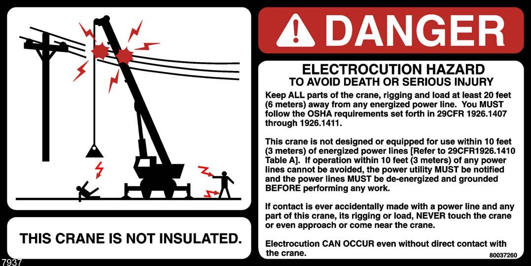
Before operating this crane in the vicinity of electrical power lines or equipment, notify the power utility company. Obtain positive and absolute assurance that the power has been turned off.
This crane is not insulated. Always consider all parts of the load and the crane, including the hoist rope, wire rope, pendant cables, and tag lines, as conductors. You, the operator, are responsible for alerting all personnel of dangers associated with electrical power lines and equipment. Do not allow unnecessary personnel in the vicinity of the crane while operating. Permit no one to lean against or touch the crane. Permit no one, including riggers and load handlers, to hold the load, load lines, tag lines, or rigging gear.
If the load, hoist rope, boom, or any portion of the crane contacts or comes too close to an electrical power source, everyone in, on, and around the crane can be seriously injured or killed.
Most overhead power lines are not insulated. Treat all overhead power lines as being energized unless you have reliable information to the contrary from the utility company or owner.
The rules in this Operator Manual must be followed at all times, even if the electrical power lines or equipment have been de-energized.
The safest way to avoid electrocution is to stay away from electrical power lines and electrical power sources.
It is not always necessary to contact a power line or power source to become electrocuted. Electricity, depending on magnitude, can arc or jump to any part of the load, load line, or crane boom if it comes too close to an electrical power source. Low voltages can also be dangerous.
Set-Up and Operation
During crane use, assume that every line is energized (“hot” or “live”) and take the necessary precautions.
Set up the crane in a position such that the load, boom, or any part of the crane and its attachments cannot be moved to within 6m (20ft) of electrical power lines or equipment. This includes the crane boom (fully extended to maximum height, radius, and length) and all attachments (jibs, rigging, loads, etc.). Overhead lines tend to blow in the wind so allow for lines’ movement when determining safe operating distance.
A suitable barricade should be erected to physically restrain the crane and all attachments (including the load) from entering into an unsafe distance from electrical power lines or equipment.
Plan ahead and always plan a safe route before traveling under power lines. Rider poles should be erected on each side of a crossing to assure sufficient clearance is maintained.
Appoint a reliable and qualified signal person, equipped with a loud signal whistle or horn and voice communication equipment, to warn the operator when any part of the crane or load moves near a power source. This person should have no other duties while the crane is working.
Tag lines should always be made of non-conductive materials. Any tag line that is wet or dirty can conduct electricity.
Do not store materials under power lines or close to electrical power sources.
Electrocution Hazard Devices
The use of insulated links, insulated boom cages/guards, proximity warning devices, or mechanical limit stops does not assure that electrical contact will not occur. Even if codes or regulations require the use of such devices, failure to follow the rules listed here ma y result in serious injury or death. You should be aware that such devices have limitations and you should follow the rules and precautions outlined in this manual at all times even if the crane is equipped with these devices.
Insulating links installed into the load line afford limited protection from electrocution hazards. Links are limited in their lifting abilities, insula ting properties , and other properties that affect their performance. Moisture, dust, dirt, oils, and other contaminants can cause a link to conduct electricity. Due to their capacity ratings, some links are not effective for large cranes and/or high voltages/currents.
The only protection that may be afforded by an insulated link is below the link (electrically downstream), provided the link has been kept clean, free of contamination, has not been scratched or damaged, and is periodically tested (just before use) for its dielectric integrity.
Boom cages and boom guards afford limited protection from electrocution hazards. They are designed to cover only the boom nose and a small portion of the boom. Performance of boom cages and boom guards is limited by their physical size, insulating characteristi cs, and operating environment (e.g. dust, dirt, moisture, etc.). The insulating characteristics of these devices can be compromised if not kept clean, free of contamination, and undamaged.
Proximity sensing and warning devices are available in different types. Some use boom nose (localized) sensors and others use full boom length sensors. No warning may be given for components, cables, loads, and other attachments located outside of the sensing area. Much reliance is placed upon you, the operator, in selecting and properly setting the sensitivity of these devices.
FIGURE2-5
United States OSHA regulations require a flagman when operating in close proximity to energized power lines.
Never rely solely on a device to protect you and your fellow workers from danger.
Some variables you must know and understand are:
• Proximity devices are advertised to detect the existence of electricity and not its quantity or magnitude.
• Some proximity devices may detect only alternating current (AC) and not direct current (DC).
• Some proximity devices detect radio frequency (RF) energy and others do not.
• Most proximity devices simply provide a signal (audible, visual, or both) for the operator; this signal must not be ignored.
• Sometimes the sensing portion of the proximity devices becomes confused by complex or differing arrays of power lines and power sources.
Do not depend on grounding. Grounding of a crane affords little or no protection from electrical hazards. The effectiveness of grounding is limited by the size of the conductor (wire) used, the condition of the ground, the magnitude of the voltage and current present, and numerous other factors.
Electrical Contact
If the crane should come in contact with an energized power source, you must:
1. Stay in the crane cab. Don’t panic
2. Immediately warn personnel in the vicinity to stay away.
3. Attempt to move the crane away from the contacted power source using the crane’s controls which may have remained functional.
4. Stay in the crane until the power company has been contacted and the power source has been de-energized. No one must attempt to come close to the crane or load until the power has been turned off.
Only as a last resort should an operator attempt to leave the crane upon contacting a power source. If it is absolutely necessary to leave the operator’s station, jump completely clear of the crane. Do not step off. Hop away with both feet together. Do not walk or run.
Following any contact with an energized electrical source, the Manitowoc distributor must be immediately advised of the incident and consulted on necessary inspections and repairs. Thoroughly inspect the hoist rope and all points of contact on the crane. Should the dealer not be immediately available, contact Manitowoc Crane Care. The crane must not be returned to service until it is thoroughly inspected for any evidence of damage and all damaged parts are repaired or replaced as authorized by your Manitowoc distributor or Manitowoc Crane Care.
Special Operating Conditions and Equipment
Never operate the crane during an electrical thunderstorm.
When operating near transmitter/communication towers where an electrical charge can be induced into the crane or load:
• The transmitter shall be deenergized OR,
• Tests shall be made to determine if an electrical charge will be induced into the crane or load.
• The crane must be provided an electrical ground.
• If taglines are used, they must be non-conductive.
• Every precaution must be taken to dissipate induced voltages. Consult a qualified RF (radio frequency) Consultant. Also refer to local, state, and federal codes and regulations.
When operating cranes equipped with electromagnets, you must take additional precautions. Permit no one to touch the magnet or load. Alert personnel by sounding a warning signal when moving a load. Do not allow the cover of the electromagnet power supply to be open during operation or at any time the electrical system is activated. Shut down the crane completely and open the magnet controls switch prior to connecting or disconnecting magnet leads. Use only a non-conductive device when positioning a load. Lower the magnet to the stowing area and shut off power before leaving the operator’s cab (if equipped) or operator’s station.
Personnel Handling
The American Society of Mechanical Engineers issued a new American National Standard entitled, Personnel Lifting Systems, ASME B30.23-2011:
This Volume establishes the design criteria, equipment characteristics, and operational procedures that are required when hoisting equipment within the scope of the ASME B30 Standard is used to lift personnel. Hoisting equipment defined by the ASME B30 Standard is intended for material handling. It is not designed, manufactured, or intended to meet the standards for personnel handling equipment, such as ANSI/SIA A92 (Aerial Platforms). The equipment and implementation requirements listed in this Volume are not the same as that established for using equipment specifically designed and manufactured for lifting personnel. Hoisting equipment complying with the applicable Volumes of the ASME B30 Standard shall not be used to lift or lower personnel unless there are no less hazardous alternatives to providing access to the, area where work is to be performed. The lifting or lowering of personnel using ASME B30-compliant hoisting equipment is prohibited unless all applicable requirements of this volume have been met.
This new standard is consistent with the U.S. Department of Labor, Occupational Safety and Health Administration (OSHA) regulations for Construction that state, in 29CFR1926.1431:
General requirements. The use of a crane or derrick to hoist employees on a personnel platform is prohibited, except when the erection, use, and dis- mantling of conventional means of reaching the worksite, such as a personnel hoist, ladder, stairway, aerial lift, elevating work platform or scaffold, would be more hazardous or is not possible because of structural design or worksite conditions.
Additional requirements for crane operations are stated in ASME B30.5, Mobile and Locomotive Cranes, ASME B30.8, Floating Cranes and Floating Derricks, and in OSHA regulations 29CFR1910.180 for General Industry and 29CFR1926.1431 for Construction
Use of a Manitowoc crane to handle personnel is acceptable provided:
• The requirements of the applicable national, state and local regulations and safety codes are met.
• A determination has been made that use of a crane to handle personnel is the least hazardous means to perform the work.
• The crane operator shall be qualified to operate the specific type of hoisting equipment used in the personnel lift.
• The crane operator must remain at the crane controls at all times when personnel are off the ground.
• The crane operator and occupants have been instructed in the recognized hazards of personnel platform lifts.
• The crane is in proper working order.
• The crane must be equipped with a boom angle indicator that is visible to the crane operator.
• The crane's Load Chart is affixed at the operator’s station and readily accessible to the operator. The total weight of the loaded personnel platform and related rigging shall not exceed 50 percent of the rated capacity for the radius and configuration of the crane.
• The crane is level within one percent of level grade and located on a firm footing. Cranes with outriggers shall have them all deployed following manufacturer's specifications.
• The crane's Operator Manual and other operating manuals are at the operator’s station and readily accessible to the operator.
• The platform meets the requirements as prescribed by applicable standards and regulations.
• For hoist rope suspended platforms:
- The crane is equipped with a hook that can be closed and locked, eliminating the throat opening.
- The crane is equipped with a functional anti-twoblock device.
- The platform is properly attached and secured to the load hook.
• For boom mounted platforms:
- The platform is properly attached and secure.
To avoid death or serious injury:
• NEVER use this crane for bungee jumping or any form of amusement or sport.
• NEVER handle personnel on the loadline unless the requirements of applicable national, state and local regulations and safety codes are met.
• NEVER permit anyone to ride loads, hooks, slings or other rigging for any reason.
• NEVER get on or off a moving crane.
• NEVER allow anyone other than the operator to be on this crane while the machine is operating or traveling.
• NEVER allow anyone on the hoist access platform while traveling.
The following standards and regulations regarding personnel handling are available by mail at the following addresses:
• ASME (formerly ANSI) B30 Series American National Safety Standards For Cableways, Cranes, Derricks, Hoists, Hooks, Jacks, and Slings; ASME B30.5, Mobile And Locomotive Cranes, and ASME B30.23, Personnel Lifting Systems, are available by mail from the ASME, 22 Law Drive, Fairfield, New Jersey, 0700-2900
• US DOL/OSHA Rules and Regulations are available by mail from the Superintendent of Documents, PO Box 371954, Pittsburgh, PA, 15250-7954.
Environmental Protection
Dispose of waste properly! Improperly disposing of waste can threaten the environment.
Potentially harmful waste used in Manitowoc cranes includes — but is not limited to — oil, fuel, grease, coolant, air conditioning refrigerant, filters, batteries, and cloths which have come into contact with these environmentally harmful substances.
Handle and dispose of waste according to local, state, and federal environmental regulations.
When filling and draining crane components, observe the following:
• Do not pour waste fluids onto the ground, down any drain, or into any source of water.
• Always drain waste fluids into leak proof containers that are clearly marked with what they contain.
• Always fill or add fluids with a funnel or a filling pump.
• Immediately clean up any spills.
Maintenance
The crane must be inspected prior to use on each work shift. The owner, user, and operator must ensure that routine maintenance and lubrication are being dutifully performed. Never operate a damaged or poorly maintained crane.
Manitowoc continues to recommend that cranes be properly maintained, regularly inspected and repaired as necessary. Manitowoc reminds crane owners to ensure that all safety decals are in place and legible. Manitowoc continues to urge crane owners to upgrade their cranes with rated capacity limiter and control lever lockout systems for all lifting operations.
Shut down the crane while making repairs or adjustments.
Always perform a function check after repairs have been made to ensure proper operation. Load tests should be performed when structural or lifting members are involved.
Follow all applicable safety precautions in this manual when performing crane maintenance as well as crane operations. Keep the crane free of mud, dirt, and grease at all times. Dirty equipment introduces hazards, wears-out faster, and makes proper maintenance difficult. Cleaning solutions used should be non-flammable, non-toxic and appropriate for the job.
Routine maintenance and inspection of this crane must be performed by a qualified person(s) according to the recommendations in the Manitowoc Crane Care Maintenance and Inspection Manual . Any questions regarding procedures and specifications should be directed to your Manitowoc distributor.
Service and Repairs
WARNING
Fall Hazard!
Working at elevated heights without using proper fall protection can result in severe injury or death. Always use proper fall protection as required by local, state or federal regulations.
Service and repairs to the crane must only be performed by a qualified person. All service and repairs must be performed in accordance with manufacturer’s recommendations, this manual, and the service manual for this machine. If there is any question regarding maintenance procedures or specifications, contact your Manitowoc distributor for assistance.
Qualified person is defined as one who by reason of knowledge, training and experience is thoroughly familiar with the crane’s operation and required maintenance as well as the hazards involved in performing these tasks.
Training and qualification of maintenance and repair personnel are crane owner’s responsibility.
Any modification, alteration, or change to a crane which affects its original design and is not authorized and approved by Manitowoc is strictly prohibited. All replacement parts must be Manitowoc approved. Such action invalidates all warranties and makes the owner/user liable for any resultant accidents.
Hydraulic Fluid:
• Do not use your hand or any part of your body to check for hydraulic fluid leaks when the engine is running or the hydraulic system is under pressure. Fluid in the hydraulic system can be under enough pressure that it will penetrate the skin, causing serious injury or death. Use a piece of cardboard, or piece of paper, to search for leaks. Wear gloves to protect your hands from spraying fluid.
• If any hydraulic fluid is injected into the skin, obtain medical attention immediately or gangrene may result.
• Do not attempt to repair or tighten any hydraulic hose or fitting while the engine is running, or when the hydraulic system is under pressure.
• Never disconnect any hydraulic lines unless the boom is fully lowered, the engine is shut off, and the hydraulic pressure is relieved. To relieve hydraulic pressure, stop the engine, turn the ignition switch to RUN and move the hydraulic controls in both directions several times.
WARNING
Pressurized Fluid Hazard!
Hydraulic pressure may still be present in portions of the hydraulic system due to accumulators or trapped circuitry.
• Hot hydraulic fluid will cause severe burns. Wait for the fluid to cool before disconnecting any hydraulic lines.
• Hydraulic fluid can cause permanent eye injury. Wear appropriate eye protection.
Moving Parts:
• Do not place limbs near moving parts. Amputation of a body part may result. Turn off the engine and wait until the fan and belts stop moving before servicing crane.
• Pinch points, which result from relative motion between mechanical parts, are areas of the machine that can cause personal injury or death. Do not place limbs or your body in contact with pinch points either on or around the machine. Care must be taken to prevent motion between pinch points when performing maintenance and to avoid such areas when movement is possible.
• Do not allow persons to stand near extending or lowering outriggers. Foot crushing could occur
Before performing any maintenance, service or repairs on the crane:
• The boom should be fully retracted and lowered and the load placed on the ground.
• Do not get under a raised boom unless the boom is blocked up safely. Always block up the boom before doing any servicing that requires the boom to be raised.
• Stop the engine and disconnect the battery.
• Controls should be properly tagged. Never operate the crane if it is tagged-out nor attempt to do so until it is restored to proper operating condition and all tags have been removed by the person(s) who installed them.
After maintenance or repairs:
• Replace all guards and covers that have been removed.
• Remove all tags, connect the battery, and perform a function check of all operating controls.
• Consult with Manitowoc Crane Care to determine if load testing is required after a structural repair is performed.
Lubrication
The crane must be lubricated according to the manufacturer’s recommendations for lubrication points, time intervals, and types. Lubricate at more frequent intervals when working under severe conditions.
Exercise care when servicing the hydraulic system of the crane, as pressurized hydraulic oil can cause serious injury. The following precautions must be taken when servicing the hydraulic system:
• Follow the manufacturer’s recommendations when adding oil to the system. Mixing the wrong fluids could destroy seals, causing component failure.
• Be certain all lines, components, and fittings are tight before resuming operation.
Tires
Warning
Possible equipment damage and/or personal injury!
Driving the crane with a tire and split-rim assembly under inflated at 80% or less of its recommended pressure can cause the wheel and/or tire to fail. Per OSHA Standard 1910.177(f)(2), when a tire has been driven under inflated at 80% or less of its recommended pressure, it must first be completely deflated, removed from the axle, disassembled, and inspected before re-inflation.
Inspect the tires for nicks, cuts, embedded material, and abnormal wear.
Ensure all lug nuts are properly torqued.
Ensure pneumatic tires are inflated to the proper pressure (refer to the Load Chart ). When inflating tires, use a tire gauge, clip-on inflator, and extension hose which will permit standing clear of the tire while inflating.
Hoist Rope
Synthetic Hoist Rope
For detailed information concerning synthetic hoist rope, refer to KZ100 Synthetic Crane Hoist Line Manual P/N 9828100734 available by contacting Manitowoc Crane Care.
During installation and setup, care must be taken to avoid overlap and crossing of wire rope and synthetic hoist ropes. Always make daily inspections of the hoist rope, keeping in mind that all hoist rope will eventually deteriorate to a point where it is no longer usable. Refuse to work with worn or damaged hoist rope.
During regular inspections, operator shall ensure that crane surfaces such as wear pads, sheaves, etc have not been damaged in a manner that can then damage the synthetic hoist rope.
NOTE: Example; if usage of a wire rope has cut grooves with sharp edges in a wear pad, they need to be addressed before the synthetic hoist rope is used in that same position.
Use only the hoist rope specified by Manitowoc as indicated on the crane’s Capacity Chart. Substitution of an alternate hoist rope may require the use of a different permissible line pull and, therefore, require different reeving.
NOTE: Hoist rope may be purchased by contacting Manitowoc Crane Care.
Wire Rope
Always make daily inspections of the rope, keeping in mind that all wire rope will eventually deteriorate to a point where it is no longer usable. Refuse to work with worn or damaged wire rope. Rope shall be taken out of service when any of the following conditions exist:
• For rotation-resistant running ropes: more than two (2) broken wires in a length of rope equal to six (6) times the rope diameter, or more than four (4) broken wires in a length of rope equal to thirty (30) times the rope diameter.
• For running ropes other than rotation resistant: six (6) broken wires in one rope lay or three (3) broken wires in one strand.
• One valley break where the wire fractures between strands in a running rope is cause for removal.
• Abrasion of the rope resulting in a 5% reduction in the original wire diameter.
• Any kinking, bird caging, crushing, corrosion, or other damage resulting in distortion of the rope structure.
• Rope that has been in contact with a live power line or has been used as a ground in an electric circuit (eg. welding) may have wires that are fused or annealed and must be removed from service.
• In standing ropes, more than three (3) breaks in one rope lay in sections beyond the end connection or more than two (2) broken wires at an end connection.
• Core deterioration, usually observed as a rapid reduction in rope diameter, is cause for immediate removal of the rope.
The following is a brief outlin e of the basic information required to safely use wire rope.
• Wire ropes wear out. The strength of a rope begins to decrease when the rope is put to use and continues to decrease with each use. Ro pe will fail if worn-out, overloaded, misused, damaged or improperly maintained.
• The nominal strength, sometimes called catalog strength, of a wire rope applies only to a new, unused rope.
• The nominal strength of a rope should be considered the straight line pull which will actually break a new unused rope. The nominal strength of a rope should never be used as its working load.
• Each type of fitting attached to a rope has a specific efficiency rating which can reduce the working load of the rope assembly or rope system.
• Never overload a rope. This means never use the rope where the load applied to it is greater than the working load determined by the rope manufacturer.
• Never “shock load” a rope. A sudden application of force or load can cause both visible external and internal damage. There is no practical way to estimate the force applied by shock loading a rope. The sudden release of a load can also damage a rope.
• Lubricant is applied to the wires and strands of a wire rope when it is manufactured. The lubricant is depleted when the rope is in service and should be replaced periodically. Refer to the Service Manual for more information.
• In the U.S.A., regular inspections of the rope and keeping of permanent records signed by a qualified person are required by OSHA for almost every wire rope application. The purpose of the inspection is to determine whether or not a rope may continue to be safely used on the application. Inspection criteria, including number and location of broken wires, wear and elongation, have been established by OSHA, ANSI, ASME and similar organizations. See the Service Manual for inspection procedures.
When inspecting ropes and attachments, keep all parts of your body and clothing away from rotating hoist drums and all rotating sheaves. Never handle the rope with bare hands.
Some conditions that lead to problems in wire rope systems include:
- Sheaves that are too small, worn or corrugated cause damage to a wire rope.
- Broken wires mean a loss in strength.
- Kinks permanently damage a rope and must be avoided.
- Ropes are damaged by knots. Rope with knots must never be used.
- Environmental factors such as corrosive conditions and heat can damage a wire rope.
- Lack of lubrication can significantly shorten the useful life of a wire rope.
- Contact with electrical wires and resulting arcing will damage a wire rope.
• An inspection should include verification that none of the specified removal criteria for this usage are met by checking for such things as:
- Surface wear; nominal and unusual.
- Broken wires; number and location.
- Reduction in diameter.
- Rope stretch (elongation).
- Integrity of end attachments.
- Evidence of abuse or contact with another object.
- Heat damage.
- Corrosion.
NOTE: A more detailed rope inspection procedure is given in the Service Manual
• When a rope has been removed from service because it is no longer suitable for use, it must not be reused on another application.
When installing a new rope:
• Keep all parts of your body and clothing away from rotating hoist drums and all rotating sheaves.
• Never handle the wire rope with bare hands.
• Follow proper instructions for removing rope from a reel.
• Apply back tension to the storage/payoff reel of the new rope to insure tight, even spooling onto the hoist drum.
• Operate the new rope - first through several cycles at light load and then through several cycles at intermediate load to allow the rope to adjust to operating conditions.
When using a wedge socket:
• Always inspect socket, wedge, and pin for correct size and condition.
• Do not use parts that are damaged, cracked, or modified.
• Assemble the wedge socket with live end of rope aligned with the centerline of pin and assure proper length of tail (dead end) protrudes beyond the socket.
Sheaves
Inspect the boom nose and hook block sheaves for proper operation, excessive wear, and damage every 50 hours or weekly. Inoperable, damaged and/or worn sheaves cause rapid deterioration of rope.
Ensure sheaves carrying ropes that can be momentarily unloaded are equipped with close fitting guards or other devices to guide the rope back into the groove when the load is reapplied. Ensure sheaves in the lower load block are equipped with close fitting guards that will prevent the ropes from becoming fouled when the block is lying on the ground with loose ropes.
To attain maximum hoist rope life and minimize hook block rotation, it is recommended that even numbers of parts-ofline be used in multiple-part reeving whenever possible.
The use of nylon (polyamide) sheaves, as compared with metallic sheaves, may change the replacement criteria of rotation-resistant hoist rope.
NOTE: The use of cast nylon (polyamide) sheaves will substantially increase the service life of rope. However, conventional rope retirement criteria based only upon visible wire breaks may prove inadequate in predicting rope failure. The user of cast nylon sheaves is therefore cautioned that a retirement criteria should be established based upon the user’s experience and the demands of his application.
Batteries
Battery electrolyte must not be allowed to contact the skin or eyes. If this occurs, flush the contacted area with water and consult a doctor immediately.
When checking and maintaining batteries, exercise the following procedures and precautions:
• Wear safety glasses when servicing batteries.
• If equipped, disconnect battery with the battery disconnect switch before disconnecting the ground battery cable. For cranes with a Cummins engine using an engine ECM: a. Ensure that the key switch has been off for 2 minutes. b. Turn the battery disconnect switch to the OFF position. c. Remove the ECM power fuse. d. Remove negative battery cables.
• Do not break a live circuit at the battery terminal. Disconnect the ground battery cable first when removing a battery and connect it last when installing a battery.
• Do not short across the battery posts to check charge. Short circuit, spark, or flame could cause battery explosion.
• If applicable, maintain battery electrolyte at the proper level. Check the electrolyte with a flashlight.
• If applicable to your crane, check battery test indicator on maintenance-free batteries.
• Check battery condition only with proper test equipment. Batteries shall not be charged except in an open, wellventilated area that is free of flame, smoking, sparks, and fire.
Engine
Fuel the crane only with the engine turned off. Do not smoke while fueling the crane. Do not store flammable materials on the crane.
Be familiar with the location and use of the nearest fire extinguisher.
Be careful when checking the engine coolant level. The fluid may be hot and under pressure. Shut down the engine and allow the radiator time to cool before removing the radiator cap.
Shut down the engine and disconnect the battery before performing maintenance. If unable to do so for the task required, keep hands clear of the engine fan and other moving parts while performing maintenance.
Be careful of hot surfaces and hot fluids when performing maintenance on or around the engine.
Do not use ether to start the engine on cranes equipped with intake manifold grid heaters.
The engine can enter into a engine exhaust cleaning mode where the exhaust temperature can be high, ensure the exhaust is not pointed at materials that can melt, burn or explode.
Transporting The Crane
Before transporting the crane, check the suitability of the proposed route with regard to the crane height, width, length, and weight.
Check load limits of bridges on the travel route and ensure they are greater than the combined weight of the crane and transporting vehicle.
When loading or unloading the crane on a trailer or railroad car, use a ramp capable of supporting the weight of the crane.
Ensure the crane is adequately secured to the transporting vehicle.
Do not use the dead end lug (1, Figure2-7) on the boom nose for tying down the boom during transport. Damage to the lug and boom can result from usage as a tie down point.
Before transporting the crane on a road or highway, first check state and local restrictions and regulations.
Either the hook block may be reeved over the main boom nose or the headache ball may be reeved over the main boom nose or auxiliary boom nose; the other must be removed. If the hook block or headache ball remains reeved on the boom, it must be secured at the tie down on the carrier to prevent swinging.
When using hookblock tie downs, excessive loading can be applied by pulling the cable too tight, particularly when reeved with multiple part lines. When the cable is hooked into the hookblock tie down, the cable should be merely “snugged-up” with adequate slack provided at the center line of sheave to anchor point. Do not draw cable taut. Care must be exercised anytime any crane function is being performed while the cable is hooked into the hookblock tie down.
Travel Operation
Only the crane operator shall occupy the crane when traveling.
When traveling, the boom should be completely retracted and lowered to the travel position and the turntable pin swing lock, if equipped, should be engaged. If equipped with boom rest, lower the boom into the boom rest and engage the turntable lock.
Strictly adhere to the guidelines and restrictions in the Load Chart for pick and carry operations.
RT and Industrial cranes are manufactured with no axle suspension system. Traveling at high speeds, especially on rough ground, may create a bouncing effect that can result in loss of control. If bouncing occurs, reduce travel speed.
Death or serious injury could result from being crushed by revolving tires.
Stunt driving and horse-play are strictly prohibited. Never allow anyone to hitch a ride or get on or off a moving crane. Follow the instructions in this manual when preparing the crane for travel.
If using a boom dolly/trailer, thoroughly read and understand all the steps and safety precautions in this manual for setup and travel.
When driving the crane, ensure the cab is down, if equipped with a tilting cab.
Secure the hook block and other items before moving the crane.
Watch clearances when traveling. Do not take a chance of running into overhead or side obstructions.
When moving in tight quarters, post a signal person to help guard against collisions or bumping structures.
Before traveling a crane, check suitability of proposed route with regard to crane height, width, and length.
Never back up without the aid of a signal person to verify the area behind the crane is clear of obstructions and/or personnel.
On cranes equipped with air-operated brakes, do not attempt to move the crane until brake system air pressure is at operating level.
Check load limit of bridges. Before traveling across bridges, ensure they will carry a load greater than the crane’s weight.
If it is necessary to take the crane on a road or highway, check state and local restrictions and regulations.
Keep lights on, use traffic warning flags and signs, and use front and rear flag vehicles when necessary. Check state and local restrictions and regulations.
Always drive the crane carefully obeying speed limits and highway regulations.
Stay alert at the wheel.
If equipped, ensure that the hoist access platform hand rail and step are in the travel configuration.
Slopes:
- Pick and carry on level surfaces only.
- Refer to the Operation Section for more detailed information on traveling on slopes.
- Driving across a slope is dangerous, as unexpected changes in slope can cause tip over. Ascend or descend slopes slowly and with caution.
- When operating on a downhill slope, reduce travel speed and downshift to a low gear to permit compression braking by the engine and aid the application of the service brakes.
Work Practices
Personal Considerations
Always adjust the seat and lock it in position, and fasten the seat belt securely before you start the engine.
Do not wear loose clothing or jewelry that can get caught on controls or moving parts. Wear the protective clothing and personal safety gear issued or called for by the job conditions. Hard hat, safety shoes, ear protectors, reflective clothing, safety goggles, and heavy gloves may be required.
Crane Access
Warning
Fall Hazard!
Working at elevated heights without using proper fall protection can result in severe injury or death.
Always use proper fall protection as required by local, state or federal regulations.
You must take every precaution to ensure you do not slip and/or fall off the crane. Falling from any elevation could result in serious injury or death.
Never exit or enter the crane cab or deck by any other means than the access system(s) provided (i.e., steps and grab handles). Use the recommended hand-holds and steps to maintain a three-point contact when getting on or off the crane.
If necessary, use a ladder or aerial work platform to access the boom nose.
Do not make modifications or additions to the crane’s access system that have not been evaluated and approved by Manitowoc Crane Care.
Do not step on surfaces on the crane that are not approved or suitable for walking and working. All walking and working surfaces on the crane should be clean, dry, slip-resistant, and have adequate supporting capacity. Do not walk on a surface if slip-resistant material is missing or excessively worn.
Do not use the top of the boom as a walkway.
Do not step on the outrigger beams or outrigger pads (floats) to enter or exit the crane.
Use the hoist access platform (if equipped) when working in the hoist area.
Wear shoes with a highly slip-resistant sole material. Clean any mud or debris from shoes before entering the crane cab/ operator’s station or climbing onto the crane superstructure. Excessive dirt and debris on the hand-holds, access steps, or walking/working surfaces could cause a slipping accident. A shoe that is not clean might slip off a control pedal during operation.
Do not allow ground personnel to store their personal belongings (clothing, lunch boxes, water coolers, and the like) on the crane. This practice will prevent ground personnel from being crushed or electrocuted when they attempt to access personal belongings stored on the crane.
Job Preparation
Before crane use:
• Barricade the entire area where the crane is working and keep all unnecessary personnel out of the work area.
• Ensure that the crane is properly equipped including access steps, covers, doors, guards, and controls.
• Conduct a visual inspection for cracked welds, damaged components, loose pins/bolts, and wire connections. Any item or component that is found to be loose or damaged (broken, chipped, cracked, worn-through, etc.) must be repaired or replaced. Inspect for evidence of improper maintenance (consult your Service Manual).
• Check for proper functioning of all controls and operator aids (for example, RCL).
• Check all braking (for example, wheel, hoist, and swing brakes) and holding devices before operation.
You must ensure that the outriggers and jack cylinders are properly extended and set before performing any lifting operations. On models equipped with outriggers that can be pinned at the mid-extend position, the outriggers must also be pinned when operating from the mid-extend position.
Clear all personnel from the outrigger area before extending or retracting the outriggers. Carefully follow the procedures in this Operator Manual when extending or retracting the outriggers. Death or serious injury could result from improper crane set up on outriggers.
Be familiar with surface conditions and the presence of overhead obstructions and power lines.
Working
Operator shall be responsible for all operations under his/her direct control. When safety of an operation is in doubt, operator shall stop the crane’s functions in a controlled manner. Lift operations shall resume only after safety concerns have been addressed or the continuation of crane operations is directed by the lift supervisor.
Know the location and function of all crane controls.
Make sure all persons are away from the crane and the Travel Select Lever is in the “N” (Neutral) position with the Parking Brake engaged before starting the engine.
Sparks from the crane’s electrical system and/or engine exhaust can cause an explosion. Do not operate this crane in an area with flammable dust or vapors, unless good ventilation has removed the hazard.
Carbon monoxide fumes from the engine exhaust can cause suffocation in an enclosed area. Good ventilation is very important when operating the crane.
Before actuating swing or any other crane function, sound the horn and verify that all personnel are clear of rotating and moving parts.
Never operate the crane when darkness, fog, or other visibility restrictions make operation unsafe. Never operate a crane in thunderstorms or high winds.
Always be aware of your working environment during operation of the crane. Avoid contacting any part of the crane with external objects.
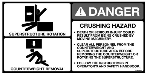
Clear all personnel from the counterweight and superstructure area before removing the counterweight.
Keep unauthorized personnel clear of the working area during operation.
Only the crane operator shall occupy the crane when in operation.
You must always be aware of everything around the crane while lifting or traveling. If you are unable to clearly see in the direction of motion, you must post a look out or signal person before moving the crane or making a lift. Sound the horn to warn personnel
Operate the crane only from the operator’s seat. Do not reach in a window or door to operate any controls.
Operate the crane slowly and cautiously, looking carefully in the direction of movement.
A good practice is to make a “dry run” without a load before making the first lift. Become familiar with all factors peculiar to the job site.
Ensure the hoist rope is properly routed on the hook block and boom nose and that all rope guards are in place.
Lifting
Use enough parts of line for all lifts and check all lines, slings, and chains for correct attachment . To obtain maximum lifting capacities, the hook block must be set up with enough parts of line. Too few parts of line can result in failure of the hoist rope or hoist. No less than three wraps of wire rope should remain on the hoist drum. No less than eight wraps of synthetic rope should remain on the hoist drum. When slings, ties, hooks, etc., are used, make certain they are correctly positioned and secured before raising or lowering the loads.
Be sure the rigging is adequate before lifting. Use tag lines when possible to position and restrain loads. Personnel using tag lines should be on the ground.
Be sure good rigging practices are being used. Refuse to use any poorly maintained or damaged equipment. Never wrap the hoist cable around a load.
If using a clam bucket, do not exceed 80% of the crane’s capacity.
Make certain the boom tip is centered directly over the load before lifting.
Ensure that all slings, ties, and hooks are correctly placed and secured before raising or lowering the load.
Be sure the load is well secured and attached to the hook with rigging of proper size and in good condition.
Check the hoist brake by raising the load a few inches, stopping the hoist and holding the load. Be sure the hoist brake is working correctly before continuing the lift.
When lowering a load always slow down the load’s descent before stopping the hoist. Do not attempt to change speeds on multiple-speed hoists while the hoist is in motion.
Watch the path of the boom and load when swinging. Avoid lowering or swinging the boom and load into ground personnel, equipment, or other objects.
Lift one load at a time . Do not lift two or more separately rigged loads at one time, even if the loads are within the crane’s rated capacity.
Never leave the crane with a load suspended. Should it become necessary to leave the crane, lower the load to the ground and stop the engine before leaving the operator’s station.
Remember, all rigging equipment must be considered as part of the load. Lifting capacities vary with working areas. If applicable, permissible working areas are listed in the Load Chart . When swinging from one working area to another, ensure Load Chart capacities are not exceeded. Know your crane!
Stop the hook block from swinging when unhooking a load. Swinging rapidly can cause the load to swing out and increase the load radius. Swing the load slowly. Swing with caution and keep the load lines vertical.
Look before swinging your crane. Even though the original setup may have been checked, situations do change.
Never swing or lower the boom into the carrier cab (if applicable).
Never push or pull loads with the crane’s boom; never drag a load.
Do not subject crane to side loading. A side load can tip the crane or cause it to fail structurally.
If the boom should contact an object, stop immediately and inspect the boom. Remove the crane from service if the boom is damaged.
When lifting a load the boom may deflect causing the load radius to increase—this condition is made worse when the boom is extended. Ensure weight of load is within crane’s capacity on Load Chart
Avoid sudden starts and stops when moving the load. The inertia and an increased load radius could tip the crane over or cause it to fail structurally.
Use tag lines (as appropriate) for positioning and restraining loads. Check the load slings before lifting.
Be sure everyone is clear of the crane and work area before making any lifts.
Never swing over personnel, regardless of whether load is suspended from or attached to the boom.
Hand Signals
A single qualified signal person shall be used at all times when:
• Working in the vicinity of power lines.
• The crane operator cannot clearly see the load at all times.
• Moving the crane in an area or direction in which the operator cannot clearly see the path of travel.
At all times use standardized hand signals - previously agreed upon and completely understood by the operator and signal person.
If communication with the signal person is lost, crane movement must be stopped until communications are restored.
Keep your attention focused on the crane’s operation. If for some reason you must look in another direction, stop all crane movement first.
Obey a signal to stop from anyone.
Jib
To avoid death or serious injury, follow the procedures in this manual during erection, stowage, and use of the jib. Install and secure all pins properly. Control movement of the jib at all times.
Do not remove right side boom nose pins unless jib is properly pinned and secured on front and rear stowage brackets.
Danger
Boom Extension Hazard!
To avoid death or serious injury, follow procedures in Load Chart , safety, and operation manuals during erection, stowage and use of jib. Install and secure all pins properly and control jib movement at all times.
Do not remove all the pins from both front and rear stowage brackets unless the jib is pinned to the right side of the boom nose.
Properly inspect, maintain, and adjust jib and mounting. When assembling and disassembling jib sections, use blocking to adequately support each section and to provide proper alignment.
Stay outside of jib sections and lattice work. Watch for falling or flying pins when they are being removed.
Parking And Securing
Danger
Tipping Hazard!
When parking the crane and leaving it unattended follow the instructions in Section 3 of this manual. Failure to comply with these instructions may cause death or serious injury
When parking on a grade, apply the parking brake and chock the wheels.
Section 3 of this manual provides instructions for parking and securing a crane when it is to be left unattended. These instructions are intended to allow the crane to be placed in the most stable and secure position. However, Manitowoc recognizes that certain jobsite conditions may not permit the boom and jib of a crane to be fully lowered to the ground. When a qualified person at a jobsite determines that it is not practical to lower the boom to the ground, we recommend the following additional instructions be followed:
• The crane should be left in the smallest, most stable, valid operational configuration that the job site practically allows.
• The crane can not be left running, with a load on the hook, or in erection mode, or in wind conditions in excess of allowed values.
• The boom should be retracted as far as is practical, the crane configured in as stable a configuration as possible (boom angle, superstructure orientation, jib angle, etc.)
• In high winds the boom and jibs should be lowered, or secured. Changing weather conditions including but not limited to: wind, ice accumulation, precipitation, flooding, lightning, etc. should be considered when determining the location and configuration of a crane when it is to be left unattended.
SHUT-DOWN
Use the following steps when shutting down the crane:
• Engage the parking brake.
• Fully retract and lower the boom.
• Engage the swing lock pin or 360 degree swing lock (if equipped).
• Place crane function power switch to OFF (if equipped).
• Place controls in neutral position.
• Shut down the engine and remove the ignition key.
• Chock the wheels, if not on outriggers.
• Lock the operator’s cab (if applicable) and install vandal guards, if used.
Cold Weather Operation
Cold weather operation requires additional caution on the part of the operator.
Check operating procedures in this manual for cold weather starting.
Don’t touch metal surfaces that could freeze you to them. Clean the crane of all ice and snow.
Allow ample time for hydraulic oil to warm up.
In freezing weather, park the crane in an area where it cannot become frozen to the ground. The drive line can be damaged when attempting to free a frozen crane.
If applicable to your crane, frequently check all air tanks for water in freezing weather.
If applicable to your crane, always handle propane tanks according to the supplier’s instructions.
Never store flammable materials on the crane.
If cold weather starting aids are provided on your crane, use them. The use of aerosol spray or other types of starting fluids containing ether/volatiles can cause explosions or fire.
Temperature Effects On Hook Blocks
The following information applies to Gunnebo Johnston crane hook blocks:
Never use a hook block in extreme temperatures...Sudden failure can occur.
Hook blocks shall not be heated above 82°C (180°F). Hook Block Working Load Limit is valid between 82°C (180°F) and service temperature given on the identification tag with normal lifting precautions.
Additional lifting precautions are required below the service temperature given on the identification tag because cold temperature begins to affect the hook block material properties.
Lifting above 75% of the Working Load Limit (WLL), at temperatures between the service temperature given on the identification tag and -40°C (-40°F), must (be) done at a slow and steady rate to avoid stress spikes common in normal hoisting dynamics.
75% of the WLL must not be exceeded, when lifting in temperatures below -40°C (-40°F).
Temperature Effects On Hydraulic Cylinders
Hydraulic oil expands when heated and contracts when cooled. This is a natural phenomena that happens to all liquids. The coefficient of expansion for API Group 1 hydraulic oil is approximately 0.00077 cubic centimeters per cubic centimeter of volume for 1°C of temperature change (0.00043 cubic inches per cubic inch of volume for 1°F of temperature change). Thermal contraction will allow a cylinder to retract as the hydraulic fluid which is trapped in the cylinder cools.
The change in the length of a cylinder is proportional to the extended length of the cylinder and to the change in temperature of the oil in the cylinder. For example, a cylinder extended 7.6m (25ft) in which the oil cools 15.5°C (60°F) would retract approximately 196mm (7 3/4in) [see Table 2-9 and Table 2-8]. The rate at which the oil cools depends on many factors and will be more noticeable with a larger difference in oil temperature verses the ambient temperature.
Thermal contraction coupled with improper lubrication or improper wear pad adjustments may, under certain conditions, cause a “stick-slip” condition in the boom. This “stick-slip” condition could result in the load not moving smoothly. Proper boom lubrication and wear pad adjustment is important to permit the boom sections to slide freely. Slow movement of the boom may be undetected by the operator unless a load is suspended for a long period of time. To minimize the effects of thermal contraction or “Stick-slip” it is recommended that the telescope control lever is activated periodically in the extend position to mitigate the effects of cooling oil.
If a load and the boom is allowed to remain stationary for a period of time and the ambient temperature is cooler than the trapped oil temperature, the trapped oil in the cylinders will cool. The load will lower as the telescope cylinder(s) retracts allowing the boom to come in. Also, the boom angle will decrease as the lift cylinder(s) retracts causing an increase in radius and a decrease in load height.
This situation will also occur in reverse. If a crane is set up in the morning with cool oil and the daytime ambient temperature heats the oil, the cylinders will extend in similar proportions.
Table 2-8 and Table 2-9 have been prepared to assist you in determining the approximate amount of retraction/extension that may be expected from a hydraulic cylinder as a result of change in the temperature of the hydraulic oil inside the cylinder. The chart is for dry rod cylinders. If the cylinder rod is filled with hydraulic oil, the contraction rate is somewhat greater.
NOTE: Operators and service personnel must be aware that load movement, as a result of this phenomena, can be easily mistaken as leaking cylinder seals or faulty holding valves. If leaking seals or faulty holding valves are suspected to be the problem, refer to Service Bulletin dealing with testing telescope cylinders. ( Service Bulletin 98-036 applies to TMS700 and Service Bulletin G06-005A applies to RT890 and RT9130.
Coeff. =0.00043 (in3/in3/ °F)
Coeff. =0.000774 (1/ °C)
Model Specific Information
Crane Access
Use the hoist access platform (1) (Figure2-10) when working in the hoist area.Overload Inspection
When the RCL system has acknowledged an overload on your crane, you must carry out specified inspections on the crane.
These inspections apply only to overloads up to 50%. For overloads of 50% or higher, crane operation must be stopped immediately and Crane Care must be contacted for corrective action.
Warning
Overload Hazard!
To avoid an accident caused by overload damage to your crane:
•Perform the inspections outlined in this publication for overloads up to 50%.
•Stop operating the crane and contact Manitowoc Crane Care immediately for overloads of 50% and higher.
NOTE: If your crane is equipped with CraneSTAR, an overload warning will be posted to the web site for review by the crane owner.
This information supplements the Rated Capacity Limiter (RCL) manual supplied with each Grove crane.
Overload warnings do NOT indicate real time events! Warnings could be sent 24 hours (or more) after the actual event.
Overload less than 25%
1 SheavesInspect all for damage.
2 Luffing Mechanism/ Cylinder Inspect for damage/leaks.
3 Collar-wear pads Inspect all for damage.
Overload from 25% to 49%
1 SheavesInspect all for damage.
2 Luffing Mechanism/ Cylinder Inspect for damage/leaks.
3 Collar-wear pads Inspect all for damage.
4 Collar-weldsInspect all for cracks.
5 Telescopic Sections Inspect for bent or twisted sections. Check the boom for straightness.
6 Lift Cylinder Head Area Inspect for bends or cracked welds.
7 Turret-Base Section Inspect for cracked welds.
8 Locking Area (Pin Booms) Inspect for elongated holes.
9 WeldsInspect for cracks.
10 Paint Inspect for cracked paint which could indicate twisted, stretched, or compressed members.
Overload less than 25%
1 Lift CylinderInspect for leaking.
2 Turntable Bearing Check bolts for proper torque.
3 Wire RopeInspect all for damage.
Overload from 25% to 49%
1 Lift CylinderInspect for leaking.
2 Turntable Bearing Check bolts for proper torque.
3 Wire RopeInspect all for damage.
4 Hoist/DrumsInspect each for damage.
5 Hoist BrakesBrakes must hold rated line pull.
6 Bearing Main Boom Pivot Pin Inspect for deformation, cracked welds.
7 Lift Cylinderlower mount Inspect pin and welds.
8 TurntableInspect for deformation, cracked welds.
9 WeldsInspect for cracks.
10 Paint Inspect for cracked paint which could indicate twisted, stretched, or compressed members.
See topic in Swing section of Service Manual.
See topic in Introduction section of Service Manual.
See topic in Swing section of Service Manual.
See topic in Introduction section of Service Manual.
Overload less than 25%
1 Stabilizer Cylinders Inspect for leaking.
2 Outrigger Pads Inspect for deformation and cracked welds.
Overload from 25% to 49%
1 Stabilizer Cylinders Inspect for leaking.
2 Outrigger Pads Inspect for deformation and cracked welds.
3 Outrigger Beams Inspect for deformation and cracked welds.
4 Outrigger Boxes Inspect for deformation and cracked welds.
5 WeldsInspect for cracks.
6 Paint Inspect for cracked paint which could indicate twisted, stretched, or compressed members.