25 minute read
OPERATING CONTROLS AND PROCEDURESRT9150E OPERATOR MANUAL


The following paragraphs describe the standard and optional controls and indicators located in the cab. Some machines may not be equipped with the optional controls shown.
NOTE: Many controls and indicators are integrated into the ECOS and RCL electronic controllers. Refer to either the ECOS Control Unit, page 3-17 or RCL Control Unit, page 3-68 for information on the controls and indicators in these electronic controllers.
The cab contains all the controls necessary for crane travel, parking and performing all craning operations.
Operational Aids
Warning
Electronic equipment on this crane is intended as an aid to the operator. Under no condition should it be relied upon to replace the use of capacity charts and operating instructions. Sole reliance upon these electronic aids in place of good operating practices can cause an accident.
Rated Capacity Limiter System
The EKS 5 or Rated Capacity Limiter (RCL) is an electromechanical sensing system designed to alert the crane operator of impending capacity when the system has been properly preset by the operator. The control panel is mounted in the front console of the operator’s cab. When an overload condition is sensed, the system provides the operator with a visual and audible warning, and locks out the control levers to prevent lowering the boom, extending the boom, or raising the main or auxiliary hoist cables.
Two additional features are included within the RCL system:
• Working Range Limitation
• Anti-two-block Device
Working Range Limitation
Refer to Working Range Limitation submenu, page 3-38.
This feature allows the crane operator to describe the crane’s working area by setting up “virtual walls”. They are referred to as virtual walls because they exist in the system and are not real walls. The virtual walls represent obstacles
(i.e. buildings, towers, poles, etc.) in the crane’s working range. They are set by defining points along the outer limits of the working area with the tip of the boom. Once the working area has been defined, the system will provide a visual and an audible warning if the boom approaches a virtual wall.
Caution
When defining virtual wall(s), always allow a safe working distance to any obstacles. Never work outside a safe working area as defined by common practice, standards, and manuals.
Warning
There are no cutouts associated with the swing angle set limitation or the work area definition features.
Anti-Two-Block Device
This device is also incorporated into the system to prevent the hook block or headache ball from coming into contact with the boom nose or boom extension. This condition will also cause a lockout of hoist up, boom down, and telescope out, and also provide a visual and an audible alarm. Refer to the RCL Control Unit, page 3-68 for more detailed information on the function of the RCL system.
RCL Boom Alarm (CE Units)
In addition to the audible warning in the cab, a visual RCL boom alarm is also mounted in the vicinity of the boom flood light to warn all personnel that a lockout has occurred.
Control Lever Lockout System
The control lever lockout system consists of hydraulic solenoid valves, located in the directional control valves. The valves are activated in such a manner as to prevent worsening the condition, i.e. boom down, telescope out, or hoist up. The control lever lockout system is used with the anti-two-block system and/or the RCL system.
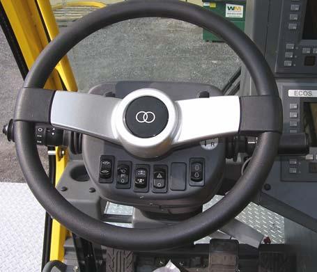
Steering Column
Refer to Figure3-1.
Transmission Shift Lever
The Transmission Shift Lever (1) is located on the right side of the steering column. It is used to select the transmission gears.
Before moving the lever up or down, pull back on the lever first. Position the lever up to actuate forward or down to actuate reverse. When the lever is in neutral, it rests in a detent.
To shift the transmission to forward first through sixth gear, rotate the knob on the transmission lever to the small 1 through 6. To shift the transmission to reverse first through third, rotate the knob to the large 1 through 3.
Turn Signal Lever
The Turn Signal Lever (2) (Figure3-1 and 3-2) is located on the left side of the steering column. Pushing the lever down causes the left indicator light, left front and left rear turn signals to flash. Pushing the lever up causes the right turn signal indicator light, the right front and right rear turn signals to flash.
Windshield Wiper/Washer Control
The Windshield Wiper Switch (2) is incorporated in the turn signal lever. Rotate the center portion of the lever to energize the windshield washer pump to spray washer fluid on the windshield.
The Windshield Wiper Switch has three positions; O, I, and II . Position the wiper/washer portion of the lever to I to operate the wiper at low speed or to II to operate the wiper at high speed. Position the wiper/washer portion of the lever to O to turn the wiper motor off and to automatically return the wiper to the parked position.
Horn
The Horn Button(3) is a push-button type switch located on the end of the turn signal lever. Depressing the Horn Button will sound the horn on the cab exterior.
Ignition Switch
The Ignition Switch (4) is located on the right side of the steering column. The switch is key operated with four positions: accessory (left position), off (vertical position), run (position between vertical and right), and start (right position).
With the Ignition Switch in the off position, all electrical power is off except for the headlights, marker lights, gauge lights, turn and stop light, cab dome light, 12V accessory outlet, and work lights.
The accessory position energizes all electrical components except the engine ECM. The run position is the same as accessory except the engine ECM is energized. The start position energizes the starter relay which in turn energizes the starter motor solenoid and cranks the engine for starting. The switch will return to run when the switch is released after the engine is started. Turn the switch to off to shut down the engine. The key can be removed in the off position only.
ItemDescription
1Transmission Shift Lever
2 Turn Signal Lever: Windshield Wiper Switch
3Horn Button
4Ignition Switch
5Left Turn Signal Direction Indicator
6Right Turn Signal Direction Indicator
7Park Brake Switch
8Headlights Switch
9Drive Select Switch (2WD/4WD)
10Hazard Lights Switch
11Engine Idle Increase/Decrease Switch
Left Turn Signal Direction Indicator
The Left Turn Signal Direction Indicator (5) is located at the top left side of the steering column. It is a green arrow light that flashes when the turn signal lever is pushed down or the top of the hazard light switch (10) is pushed to on.
Right Turn Signal Direction Indicator
The Right Turn Signal Direction Indicator (6) is located at the top right side of the steering column. It is a green arrow light that flashes when the turn signal lever is pushed up or the top of the hazard light switch (10) is pushed to on.
Park Brake Switch
NOTE: The parking brake must be set before the outrigger controls will operate.
The Park Brake Switch (7) is located on the left side of the steering column. The switch is used to apply and release the parking brake on the axle. The ECOS icon is red when the brake is applied. The icon is gray when the brake is released.
Headlights Switch
The Headlights Switch (8) is located on the left side of the steering column. The bottom position is off. The center position will light the marker, clearance and gauge lights. The top position will turn on the headlights in addition to the marker, clearance and gauge lights. When switched to either ON position the switch is backlit green.
NOTE: When the front outrigger box is electrically connected, only the headlights in the outrigger box will illuminate. Wh en the front out rigger box is electrically disconnected, only the headlights located on the carrier fender and decking will illuminate.
When the headlight switch is in the ON position and the transmission shifter is in the reverse position, only the two backup lamps on the rear fender and decking will illuminate if the rear outrigger box is electrically disconnected.
Drive Select Switch
NOTE: Four-wheel drive must be engaged to operate the outriggers.
The Drive Select Switch (9) is located on the bottom center of the steering column. Push the top of the switch to select 4 wheel drive (low) or the bottom of the switch to select 2 wheel drive (high). The ECOS icon is yellow when in 4WD or gray when in 2WD.
Hazard Lights Switch
The Hazard Lights Switch (10) is located on the bottom center of the steering column. Push the top of the switch to cause the four turn signal lights and two turn signal indicator lights to flash at the same time.
Engine Idle Increase/Decrease Switch
The Engine Idle Increase/Decrease Switch (11), on the right side of the steering column, is used to set the engine operating speed. It is a two position (+/-) momentary switch. Push and hold either the top or bottom of the switch to increase or decrease engine speed. Release the switch to hold the engine at the current speed. Pressing the foot pedal will increase engine speed above the “hold” speed. Releasing the foot pedal causes the engine to return to the “hold” speed.
Steering Column Left Side And Floor
Refer to Figure3-2.
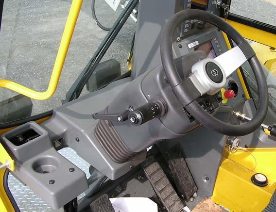
Steering Column Tilt/Telescope Lever
The Steering Column Tilt/Telescope Lever (1) is on the steering column below the turn signal lever. Rotate the lever counterclockwise to loosen the steering column for adjustment. The steering column can now be tilted or telescoped in and out. After adjustment tighten the lever by turning clockwise.
The lever can be re-positioned; push in and rotate to the desired position then pull the lever out.
Warning
Loss of Control Hazard!
Never operate the crane with the steering column adjustment lever loose. Serious injury or property damage may result.
Cup Holder
Location to hold a beverage container (3) (Figure3-2).
360° Swing Lock Pedal
The 360° Swing Lock Pedal (4) is located to the left of the swing brake pedal on the left side of the cab floor. The 360° swing lock secures the superstructure in any position.
When the pedal is up, the swing lock is disengaged and the superstructure can be rotated. Pushing down on the pedal engages the swing lock. To disengage the swing lock pull up on the release lever at the top of the pedal.
Swing Brake Pedal
The Swing Brake Pedal (5) is located on the left side of the cab floor. The Swing Brake Pedal is used to actuate the swing brake to slow or stop swing motion. Braking is proportional to pedal depression.
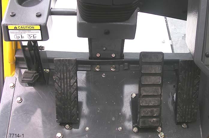
Service Brake Foot Pedal
ItemDescription
1Steering column tilt/telescope lever
2 Turn Signal Lever: Windshield Wiper Switch
3Cup Holder
4360° Swing Lock Pedal
5Swing Brake Pedal
6Service Brake Foot Pedal
7Foot Throttle Pedal
The Service Brake Foot Pedal (6) is the second pedal from the right on the cab floor. Depressing the pedal controls the application of the service brakes to stop the vehicle. This pedal must be depressed to start the engine.
Throttle Pedal
The foot Throttle Pedal (7) is located on the right side of the cab floor. The pedal is used to control engine speed. The pedal controls engine speed proportionately to the applied foot pressure. The pedal is connected electrically to the engine ECM.
Right Side Console
Refer to Figure3-3.
RCL Override Switch (Non-CE Certified Cranes)
The key operated RCL Override Switch (2) is located on the front of the console below the 12 volt accessory outlet. It is used to override the RCL in the event of an emergency that requires placing the crane in a safer position because of a malfunction or when rigging the crane to defeat the anti-twoblock switch.
Refer to RCL Override, page 3-73 for more information.
Warning
Tipping Hazard!
Do not operate crane with the RCL function OFF without being in communication with personnel on the ground observing the crane’s operation. Serious injury or damage to the crane may result.
• Key in center position: the RCL is on and actively monitoring all craning functions.
• Turn key to the right and hold: RCL shutdown function is overridden; crane functions are no longer monitored
• Turn key to the left and hold: RCL shutdown and antitwo-block functions are no longer monitored.
Refer to RCL Control Unit, page 3-68 for detailed descriptions and instructions.
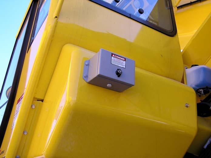
RCL Emergency Override Switch and Indicator (CE Certified Cranes)
Warning
Loss of RCL Monitoring Hazard!
The RCL Emergency Override Switch is to be used in emergency situations only.
Do not operate the crane with the RCL overridden during normal operations.
When the RCL is overridden, always have a helper on the ground to signal you.
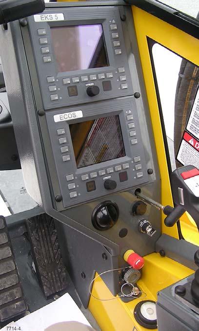
RCL Control Panel
The RCL Control Panel (1) is located at the top of the right side console. This panel is used to setup a lift and monitors all craning functions. Refer to RCL Control Unit, page 3-68 for detailed descriptions and instructions.
The RCL system, when programmed accurately, will lockout the three craning functions—boom down, telescope extend, and hoist up—when a lift is attempted at or above the crane's capacity or when a two-block condition exists. Locking out these three functions prevents the overload or two-block condition from worsening.
The RCL emergency override switch is located inside a keylocked single-door enclosure (1, Figure3-4) that is attached to the outside rear of the operator's cab. The switch is a two- position momentary rocker switch with integral indicator that, when actuated, will override and prevent the RCL, for a period of 30 minutes, from locking out the three craning functions (boom down, telescope extend, and hoist up) should an overload or two-block condition occur.
Overriding the RCL with this switch should only be done in the case of an emergency or when servicing the boom.
The indicator in the override switch will illuminate red and the RCL and A2B override indica tors on the RCL display will flash to indicate the switch has been activated. Upon activation, all craning function movements are reduced to 15% of their normal maximum speeds.
The RCL override function is automatically cancelled after 30 minutes. The RCL override function can also be cancelled by the operator by either pressing the RCL emergency override switch a second time, by turning off the engine, or by turning the crane function power switch off.
Refer to the RCL operator's manual for more information.
The individual buttons have a different function in each menu. The display shows various indicators about the crane, the engine, outriggers, boom, etc. Many crane functions are also controlled by the ECOS system.
Refer to ECOS Control Unit, page 3-17 for detailed descriptions and instructions.
Emergency Stop Switch
The Emergency Stop Switch (4) is located on the right center console. Pressing this switch will shut down the engine.
Turntable Lock Pin Control Handle
The Turntable Lock Pin Control Handle (5) is located on the lower right side console. The purpose of the turntable lock pin is to lock the superstructure in position directly over the front (0°) or rear (180°). Pull the handle out to disengage the swing lock. Push it in to engage the lock, preventing the superstructure from turning.
Accessory Outlet
The Accessory Outlet (6) is located on the right side console. It provides an outlet for the operator to plug in a 12 vdc accessory. This outlet should be used only for components requiring 8 amps or less.
Diagnostic Connector
The electrical Diagnostic Connector (7) is located on the right side console. It can be used for troubleshooting engine faults and conditions.
The connector is designed to connect a laptop computer, with appropriate cable and engine or electrical system software, to the crane for diagnostic work.
Level Indicator
FIGURE3-4
ECOS Control Panel
The ECOS Control Panel (3) is located on the right side console. Various menus are displayed on the ECOS display.
The Level Indicator (8) is located on the right side of the cab below the right side console. The indicator provides the operator with a visual aid in determining the level of the crane. Refer to the Service Manual to determine the accuracy and how to adjust the level indicator.
Overhead Controls And Features
Refer to Figure3-5.
Cab Circulating Fan
The Cab Circulating Fan (5) is located on the right front side of the cab, above the window frame. A swivel allows the fan to be rotated and a switch on the fan base controls the fan. The switch has a high, low and off position.
Right Side Window Latch
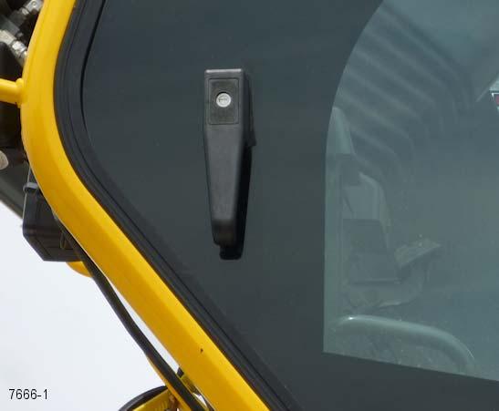
The window on the right side of the cab can be opened. Squeeze latch (6) to release the window and slide forward. To close slide the window rearward until the latch engages.
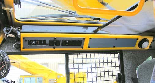
Overhead Console (Right Side)
Refer to (7) Figure3-5 and Figure3-6.
ItemDescription
1Skylight Window Latch
2Skylight Wiper
3Skylight Sunscreen
4Cab Overhead Light
5Cab Circulating Fan
6Window Latch
7Overhead Console
Skylight Window Latch
The Skylight Window Latch (1) is at the front of the window. Squeeze the latch and slide the window to the rear to open. to close slide the window forward until the latch engages.
Skylight Wiper and Wiper Motor
The Skylight Wiper (2) is controlled by the wiper switch, (5) (Figure3-6), and operated by the indicated motor.
Skylight Sunscreen
The Skylight Sunscreen (3) is used to diminish direct sunlight. The sunscreen is self retracting and can be set to screen all the light or adjusted rearward by moving it into the notches provided.
Overhead Light
The cab Overhead Light (4) is on the right rear corner of the cab overhead console and provides illumination in the cab. The Overhead Light is controlled by a switch on the light.
ItemDescription
1Heater/air Conditioner Fan Switch
2Heater Control Switch
3Air Conditioning Switch
4Boom Light Switch (Optional)
5Skylight Wiper Switch
6Work Lights Switch
7Aircraft Warning Light Switch (Optional)
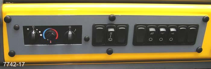
8Exhaust System Cleaning Switch
Heater/Air Conditioner Fan Switch
The Heater/Air Conditioner Fan Switch (1) controls the cab fan’s speed. Fan speed controls the volume of heated air output (or cooled air output) of the fan. Settings are off, low speed, medium speed, and high speed.
Heater Control Switch
The Heater Control Switch (2) controls intensity of heating. Turn the switch to the right (clockwise) to open the valve for heat. (Heat comes from heated fluid going through the heater coil.) Turn the switch to the left (counterclockwise) to close the valve to stop fluid flow and minimize heat.
Air Conditioner Switch
The Air Conditioning Switch (3) controls the operation of the optional air conditioning system. Settings are off (O) and on (I).
Boom Light Switch (Optional)
The Boom Light Switch (4) controls the boom light (the flood light on the boom base section). Press the top of the switch to turn on the flood light. Press the bottom of the switch to turn the flood light off.
Skylight Wiper Switch
The Skylight Wiper Switch (5) controls the skylight wiper motor. Toggle the switch from; off, through six intermittent timed positions, to low and high. Pushing the switch up from the off position energizes the wiper motor. Push the switch down to off to stop the motor and return the wiper blade to the parked position.
Work Lights Switch
The Work Lights Switch (6) controls the crane’s work lights mounted on the bottom front of the cab. Press the top of the switch to turn on the work lights. Press the bottom of the switch to turn off the work lights.
Aircraft Warning Light Switch (Optional)
The Aircraft Warning Light Switch (7) controls the optional flashing light installed on the boom nose. Press the top of the switch to turn on the aircraft warning light. Press the bottom of the switch to turn off the light.
Exhaust System Cleaning Switch (T4i Engines
Only)
Warning
Fire or Burn Hazard!
During the regeneration process the exhaust becomes very hot. Do not park the vehicle near flammable objects. Use caution near the exhaust tailpipe during regeneration as it will become very hot.
The Engine Exhaust System Cleaning Switch (8) (Figure3-6) is located on the right side of the overhead control panel. This switch is a three position switch, Inhibit Regen/Permit Regen/Start Regen. Press this switch to start Exhaust System Cleaning or to disable Exhaust System Cleaning:
• Start Regeneration (7649-10)
• Inhibit Regeneration (7649-11)
To manually regenerate, set the crane parking brake, the crane transmission must be in neutral and have the brake and throttle pedals released. Refer to Exhaust System Cleaning (Tier 4 Engines Only), page 3-109 for a description of when manual regeneration is needed.
Set up a safe area around the crane’s exhaust; remove tools, rags, grease or any debris from the engine exhaust area.
With the engine idling push the Exhaust System Cleaning (9) to initiate regeneration.
Within 5 seconds the engine should rev up to 1000 to 1400 rpm. The engine will continue to run at this speed for up to 45 minutes.
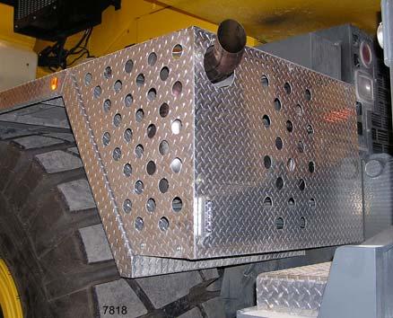
As a warning, the light (1, Figure3-7) below the exhaust pipe (2, Figure3-7) will blink during regeneration.
Pressing the brake or throttle pedal during regeneration or activating the Inhibit Regen Switch will interrupt the regeneration process.
Make sure the crane and surrounding area are monitored during manual regeneration. If any unsafe condition occurs, shut off the engine immediately.
During this period the sound of the engine may change. When regeneration is complete the engine will return to it’s normal idle speed.
Engine Throttle Switch
With the engine running press and release the top of the switch (9) (Figure3-6) to increase the engine to full throttle. Press and hold the switch to slowly increase the engine rpm. Press the bottom of the switch to return the engine to normal idle speed.
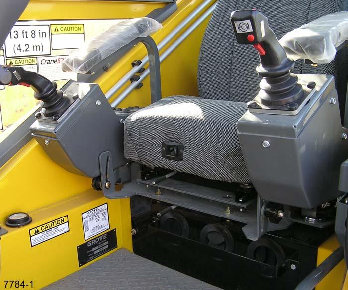
SEAT-MOUNTED CONTROLS
Refer to Figure3-8.
ItemDescription
1Right-hand Armrest Controls
2Right-hand Armrest Adjustment Knob
3Seat Adjustment Lever
4Seat Assembly Adjustment Lever
5Seat Back Adjustment Lever
6Left-hand Armrest Adjustment Knob
7Left-hand Armrest Controls
Right-Hand Armrest Assembly
The right-hand armrest (1) includes the dual axis joystick, control panel and armrest, refer to Right-Hand Armrest Controls, page 3-11. Use the adjustment knob (2) below the controller assembly to adjust its vertical position.
Seat Adjustment Lever
The Seat Adjustment Lever (3) is used to move just the seat forward or back. Push the lever to the left to release the latch and move the seat. Release the lever and slightly move the seat until the lever engages.
Seat Back Adjustment Lever
The Seat Back Adjustment Lever (5) is used to adjust the angle of the seat back. Push the lever to the right and either lean forward so the seat moves up or lean back against the seat to lean it backwards. Release the lever and allow the seat back to engage a locking point.
Seat Assembly Adjustment Lever
The Seat Assembly Adjustment Lever (4) is used to move the seat and controllers forward or back. Push the lever to the left to release the latch and move the seat. Release the lever and slightly move the seat until the lever engages.
Armrest Adjustment Knob
The Armrest Adjustment Knobs (2, 6) are used to set the vertical angle of the controllers. Turn the knob to the left to release the adjustment and to the right to tighten.
Left-Hand Armrest Assembly
The left-hand armrest (7) includes the dual axis joystick, control pane l and armrest, refer to Left-Hand Armrest Controls, page 3-13. Lift up on the controller assembly to move for seating, push down to use the controller for operation. Use the adjustment knob (6) below the controller assembly to adjust its vertical position. Crane functions are disabled when the armrest is raised.
RIGHT-HAND ARMREST CONTROLS
Refer to Figure3-9.
NOTE: All switches on this controller are momentary rocker type. Press once to turn on the function, press again to turn the function off.
Main Hoist or Telescope/Boom Lift Controller
The Main Hoist or Telescope/ Boom Lift Controller (1) is located on the right armrest. The controller is used to operate the main hoist and telescope the boom in and out or raise and lower the boom. The controller must be used in conjunction with the main hoist switch (5), lift switch (6) or telescope switch (7).
NOTE: A function is active when the icon on the ECOS display is green. Press the associated switch to toggle the function.
Main Hoist: Push the controller forward to let out the main hoist cable. Pull the controller back to reel the main hoist cable in. Refer to Hoist Operation, page 3-154.
Boom Raise/Lower: Push the controller to the right to lower the boom. Push the controller to the left to raise the boom. Refer to Elevating/Lowering the Boom, page 3-130.
Boom Telescope: Push the controller to the right to telescope out. Push the controller to the left to telescope in. Refer to Telescoping the Boom, page 3-132.
FIGURE3-9
High Speed Main and Auxiliary Hoist Boost Button
NOTE: Depending upon the crane configuration and conditions, the maximum speeds may be automatically limited by the ECOS system to prevent damage to the crane.
The High Speed Boost Rocker Switch (2) for both hoists is located on the top of the right-hand joystick controller. For momentary high speed operation; push and hold the switch to the left, release for normal speed.
To toggle continuous high speed operation; push the switch to the right to turn high speed on or off.
When high speed boost is active either the ECOS icon or will turn yellow depending on which function is selected.
Work Horn Button
The Work Horn Button (3) is on the front of the right joystick. Press in on the button to sound the horn to warn or get the attention of others.
Hoist Rotation Indicators
The Hoist Rotation Indicators (4) are located on each hoist control lever. The indicators are electronically driven by a signal from an electronic transmitter and sensor attached to each hoist. A pulsating signal is sensed by the operator’s thumb during hoist operation.
Main Hoist (I) Switch
ItemDescription
1Boom Lift or Telescope/Main Hoist Controller
2High Speed Boost Rocker Switch
3Work Horn Button
4Hoist Rotation Indicator
5Main Hoist Switch
6Boom Lift Switch
7Boom Telescope Switch
8Luffing Jib Switch (Optional)
9Cab Tilt Switch
NOTE: All switches on this controller are momentary rocker type. Press once to turn on the function, press again to turn the function off.
The Main Hoist Switch (5) is located on the right armrest. The switch is used to turn on the main hoist function by pushing the top of the switch. Use the joystick controller (1) to activate the main hoist function after switch is turned on. Push the top of the switch again to turn the function off.
Boom Lift Switch
The Boom Lift Switch (6) is located on the right armrest. The switch is used to turn the lift function on by pushing the top of the switch. Use the telescope controller (1) to activate the lift function after the boom lift switch is turned on. Push the top of the switch again to turn the function off.
Boom Telescope Switch
The Boom Telescope Switch (7) is located on the right armrest. The switch is used to turn on the telescope function by pushing the top of the switch. Use the telescope controller (1) to activate the telescope function after switch is turned on. Push the top of the switch to turn the function off.
Luffing Jib Switch (Optional)
The hydraulic Luffing Jib Switch (8) is located on the right armrest. The switch is used to turn on the luffing jib function by pushing the top of the switch. Use the ECOS control unit to control the luffing jib function after switch is turned on.
Refer to Raising and Lowering the Hydraulic Boom Extension, page 3-156 and Luffing jib, F7, page 3-48 for more information on the hydraulic luffing jib.
Cab Tilt Switch
The Cab Tilt Switch (9) is located on the right arm rest. It allows the cab to be tilted either up or down. Push the top of the switch to raise the cab or the bottom of the switch to lower the cab.
NOTE: Park brake must be engaged to operate the cab tilt feature and cab must be completely down (at zero level) for the drive functions to be enabled.
LEFT-HAND ARMREST CONTROLS
Refer to Figure3-10.
NOTE: All switches on this controller are momentary rocker type. Press once to turn on the function, press again to turn the function off.
Auxiliary Hoist/Swing Gear Controller
The Auxiliary Hoist/Swing Gear Controller (1) is located on the left armrest. The controller is used to operate the auxiliary hoist and swing the superstructure. The controller must be used in conjunction with the Auxiliary Hoist Switch (7) or Swing Brake Switch (5).
NOTE: A function is active when the icon on the ECOS display is green. Press the associated switch to toggle the function.
Auxiliary Hoist: Push the controller forward to let out the auxiliary hoist cable. Pull the controller back to reel the auxiliary hoist cable in.
Swing Gear: Push the controller to the right to rotate the superstructure to the right (clockwise). Push the controller to the left to rotate the superstructure to the left (counterclockwise).
High Speed Lift/Telescope Boost Button
NOTE: Depending upon the crane configuration and conditions the lift and or telescope speeds may be automatically limited by the ECOS system to prevent damage to the crane.
The high speed boost rocker switch (2) for the lift and telescope function is located on the top of the left-hand joystick controller.
Push and hold the switch to the left for high speed operation, release for normal speed.
Push the switch to the right to turn high speed on or off, for continuous high speed operation.
When high speed boost is active either the ECOS icon or will turn yellow depending on which function is selected.
Swing Gear Freewheel Button
Swing Gear Freewheel Button is used when the superstructure will be allowed to rotate to self-center over the load or to minimize side loading due to tandem crane operation.
Warning
Tipping Hazard!
When Swing Gear is in freewheel, the upper structure is free to rotate. Ensure that the crane is only operated within the load chart capacity range to lift the load. Further, ensure that the crane is not allowed to rotate into external objects or hazardous areas. Death, serious injury or property damage may result.
The Swing Gear Freewheel Button (3) is used to switch off the swing gear brake.
Move the control lever to zero position, press and hold the button, the swing gear brake is released and the indicator lamp on the ECOS control panel goes out.
Release the button to re-engage the swing gear brake, the indicator lamp illuminates.
ItemDescription
Hoist Rotation Indicators
The Hoist Rotation Indicators (4) are located on each hoist control lever. The indicators are electronically driven by a signal from an electronic transmitter and sensor attached to each hoist. A pulsating signal is sensed by the operator’s thumb during hoist operation.
Swing Gear Switch
The Swing Gear Switch (5) is located on the left armrest. The switch is used to activate the swing gear control circuit in order to rotate the superstructure. Push the top of the switch, the icon on the ECOS display will turn green. Use the swing gear controller (1) to rotate the superstructure after the switch is turned on. Push the top of the switch again to turn the function off.
Crane Function Switch
The Crane Function Switch (6) is located on the left armrest. The switch is used to stop all crane functions to prevent inadvertent operation of functions due to bumping the controllers while roading or other operation. Push the top of the switch: the icons on the ECOS display will turn red; swing, both hoists, lift, tele scope and the luffing jib will become inoperative.
To activate a craning function after pressing this switch, press the appropriate function’s switch.
Auxiliary Hoist (II) Switch
The Auxiliary Hoist Switch (7) is located on the left armrest. The switch is used to turn on the auxiliary hoist function by pushing the top of the switch. Use the joystick controller (1) to activate the auxiliary hoist function after switch is turned on. Push the top of the switch again to turn the function off.
FIGURE3-10
1 Auxiliary Hoist/Swing Gear Controller
2High Speed Boost Rocker Switch
3Swing Gear Freewheel
4Hoist Rotation Indicator
5Swing Gear Switch
6Crane Function Switch
7Auxiliary Hoist Switch
8Differential Lock Switch
9Rear Steer Control Switch
10Lift Up Switch (CE Option)
Differential Lock Switch (Optional)
The Differential Lock Switch (8) is located on the left armrest and is used to lock the right and left wheels in a tandem set. The differential lock increases traction on slippery roads. The differential lock switch is a momentary rocker switch. NOTE: Release the throttle before using this switch. Push and hold the top of the switch to engage the differential lock, the icon on the EC OS display will turn red. Release the switch to dis-engage the differential lock.
Caution
Vehicle Control Hazard!
Do not operate the differential lock on dry roads, while the crane wheels are spinning or at speeds over approximately 10mph (16 km/h). Damage to the vehicle may result.
Rear Steer Control Switch
The Rear Steer Control Switch (9) is located on the left armrest. Push the top of the switch to turn the rear wheels to the right, causing the crane to turn to the left. Push the bottom of the switch to turn the rear wheels to the left, causing the crane to turn to the right. Release the switch to return to the center off position. An indicator on the ECOS main menu indicates if the rear wheels are not centered.
Lift Switch (CE Option)
The Lift Switch (10) is located on the left armrest. When in an overload condition the RCL will lockout boom lift. Push the top of the switch to override the lockout condition to decrease the boom radius by raising the boom.
Miscellaneous Cab Controls And Features
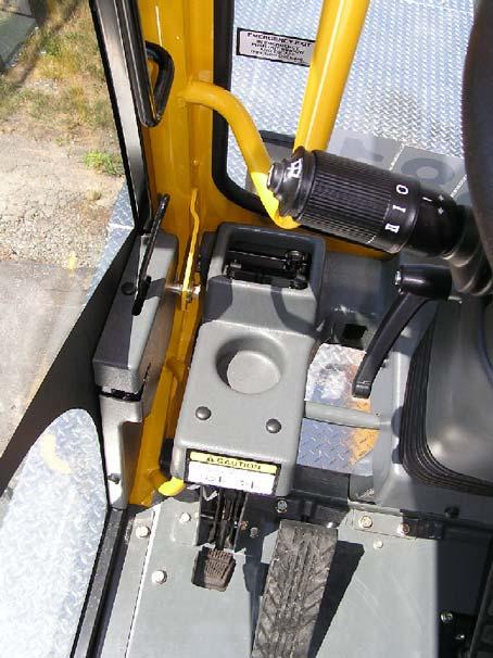
Cab Door
Outside Handle/Latch
Refer to Figure3-11.
Rotate the handle counterclockwise to release the door latch and slide the door to the rear.
After exiting the cab pull the handle towards the front of the cab, sliding the door completely until it latches.
Inside Door Latch
Refer to Figure3-12.
The door will latch if slid fu lly open and will need to be unlatched to close the door.
When seated, and before lo wering the left-hand armrest controls, move the inside door handle (1) to the front and use the grab handle (2) above the door latch to slide the door forward until it latches.
To open the door, pull the door handle to the rear; the latch releases and the door slides rearwards.
Fire Extinguisher
The Fire Extinguisher is located on the left rear side of the cab behind the operator’s seat. The Fire Extinguisher is a BC rated dry type fire extinguisher for emergency use.
Emergency Exit
The front window is considered the Emergency Exit. In an emergency push out on the window and exit through the opening.
Dead Man’s Switch and Seat Contact Switch
The dead man’s switch is located on the front of each joystick controller handle.
Published 2-18-2016, Control # 614-00 Grove
The seat contact switch (not visible) is located inside the seat.
Together these switches protect all crane functions. You must sit on the crane cab seat or must be pressing at least one of the dead man’s switches to operate a crane function. If you stand up during crane movement or the dead man’s switch is not pressed, all crane movements are brought to a complete stop within three seconds even if the control lever is moved.
Jib Release Pole
The Jib Release Pole is stored on the right side of the cab. It is used by the operator to release the jib locking mechanism from the ground.
RCL Lockout Alarm
The RCL Lockout Alarm sounds when the RCL senses an unsafe condition:
- Capacity overload
- Swing angle set limitation
- Work area definition
- Anti-two-block device
The RCL warning lights (red, yellow, green) are located on the front of the cab below the work lights.
Refer to RCL Control Unit, page 3-68 for more information.