6 minute read
RT9150E OPERATOR MANUALOPERATING CONTROLS AND PROCEDURES


If the values entered are not permissible, the values on the telescope indicators (2) (Figure3-60) turn red.
If the values entered are permissible, the values on the telescope indicators (2) turn green.
The display (1) shows the symbol for the current status.
Published 2-18-2016, Control # 614-00 Grove
Warning Messages
ECOS differentiates between warning messages and error messages, see Error Messages, page 3-66. A warning message indicates that certain values do not correspond to a set value.
In the event of a warning message, the following lamps flash:
• the Warning/Error indicator (1) (Figure3-61)
• the A button lamp (2).
FIGURE3-61
Press the A button (5) next to the flashing lamp to open the Warning submenu.
The warning message is acknowledged, lamp (2) lights up (does not flash any longer).
When all warning messages have been acknowledged, lamp (1) and lamp (2) lights up.
Both lamps start to flash again as soon as a new warning occurs.
Meaning of the Symbols
The color of the symbols indicate whether a warning message is active in the corresponding area:
• Symbol grey, no warning message.
• Symbol red, warning message.
Carry out the following procedures if a symbol is displayed in red.
Exiting the Submenu
You can exit the submenu at any time.
Press the Esc button (1) (Figure3-62) once. The same menu opens that was open before the Warnings submenu opened.

FIGURE3-62
If the same warning messages are still present, the lamps (1) and (2) (Figure3-61) light up.
If no warning message is present, both lamps will go out. Both lamps start flashing again as soon as a new warning message occurs.
Caution
Equipment Damage Hazard!
Keep alert for warning messages. When warning messages appear take appropriate action to prevent malfunction and possible damage to the crane.
ItemDescription
1Fuel level
2Low steering pressure (CE option)
3Voltage monitoring
4Transmission oil temperature
5Hoist fifth wrap indicator
6Low brake pressure
7 Ambient air temperature, -29°C (Cold Weather Option)
8Engine warning
9Pre-tension the counterweight
10Replace the hydraulic oil filter
11Anemometer not connected
12Engine stop
13Hydraulic oil temperature
14Exhaust System Cleaning Required (T4i Engine)
15Inhibit Exhaust System Cleaning (T4i Engine)
16 High Exhaust System Temperature (HEST) (T4i Engine)
Refer to the following table for a description of each item listed above.
The fuel tank is only filled up to a level of approximately 5%. Refuel before the fuel is used up.
When the fuel tank is almost empty, air is sucked in and you must bleed the fuel system, refer to the Service Manual.
Inspect the steering system for leaks and check the accumulator charge. Refer to the Service Manual.
The voltage in the electrical system is too high or too low.
Display of the current voltage, refer to Monitoring submenu, page 3-47.

Indicates when five wraps or less of cable remain on either hoist.
Inspect the brake system for leaks and check the accumulator charge. Refer to the Service manual.
The outside air temperature is below -29°C (-20°F).
Malfunction in the engine, switch off engine immediately, refer to the Service Manual.
The pre-tensioning pressure on the counterweight is lower than acceptable.
Pre-tension the counterweight, refer to Counterweight Submenu, page 3-49.
Replace the corresponding hydraulic oil filter as soon as possible, refer to Service Manual.
Connect the anemometer to the electrical power supply; refer to Anemometer/Aircraft warning Light, page 4-51.
The engine has stopped running.
The temperature of the hydraulic oil is outside the operational range.
14 Exhaust System Cleaning Required
15 Inhibit Regen
16 High Exhaust System Temperature (HEST)
When the Exhaust System Cleaning indicator illuminates or flashes start the regeneration process.
The indicator will be lit continuously during the early stages of clogging. If the system continues to clog, the indicator will begin to flash and a slight engine derate will occur.
If even more clogging occurs, the engine warning light (8) will illuminate red in addition to the Exhaust System Cleaning indicator and a severe engine derate will occur
When the Regen Switch (8) (Figure3-6) is in the inhibit regeneration position, this indicator is red and both manual and active regeneration will be inhibited.
During regeneration it is possible for the engine exhaust to reach temperatures exceeding 1200° F. The HEST indicator will illuminate red to warn the operator of when temperatures reach 1247°F (675°C) and will stay on until the temperature falls below 1157° F (625° C).
Error Messages
If ECOS detects an error, an error message is indicated by two flashing lamps, (Figure3-64):
• The Warning/Error indicator lamp (1)
• the ? button lamp (2).
FIGURE3-64
When all error messages have been acknowledged, lamp (1) and lamp (2) lights up.
Both displays start to flash again as soon as a new error occurs.
Opening the Submenu
To determine what the error is, you must open the Error submenu by pressing the ? button (2) (Figure3-65) once. The button is only active when the lamp (1) flashes or lights up.

FIGURE3-65
Exiting the Submenu
You can exit the Error submenu at any time. Press the Esc button (1) (Figure3-66) once. The same menu opens that was open before the Error submenu opened.
FIGURE3-66
NOTE: All errors remain saved until you switch off the ignition, even those errors of which the cause has been eliminated in the meantime. All existing errors are treated as new errors and displayed again after turning on the ignition.
Error Submenu
FIGURE3-67
ItemDescription
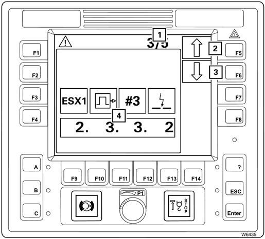
1Display of current error/total errors
2Press to go to next error
3Press to see the previous error
4Error display
Refer to the following table for a description of each item listed above.
Item (2) shows the error total, and item (1) shows which error is currently displayed.
For example, 3/5, means:
•that error 3 is shown
•and there is a total of 5 errors.
If the error shown is not acknowledged, the lamp next to the Enter button (3) lights up.


To acknowledge the error, press the Enter button (3) once.
If there are further errors, the next error is displayed and can be acknowledged.
When all errors have been acknowledged, you can retrieve any pending errors using the buttons next to the symbols (1) and (2).
(1) Next error, F5
(2) Previous error, F6
Every time you press a button, the next error will be displayed.
When you keep a button pressed, all errors are shown one after the other continuously.
If all errors have not been acknowledged, the ______buttons have no function, the symbols are grey.
Each error is defined by an error code (5) and the symbols (1) to (4).

The symbols stand for:
(1) The faulty device
(2) The error group
(3) The index within the group
(4) The type of error
The error code (5) consists of 4 digits, e.g. 2332.
Always note down the error code before contacting Crane Care.
Rcl Control Unit
The RCL control panel (EKS 5) is located on the top right side console. Various menus are displayed on the RCL display. The menus are operated using buttons F1 to F14. The individual buttons have a different function in each menu. The functions of the buttons in the display menu correspond to the symbols next to or above the buttons. After the button is pressed and released, the function displayed is executed.

Common Elements
This section describes the operating elements that are the same for all menus.
FIGURE3-68
ItemDescription
1 RCL display
Main menu overview
2Sensor for brightness
3Error/warning message
4Buttons F1 to F14
5Sensor for brightness
6 Opening the Error submenu
Error submenu overview
ItemDescription
7Exiting the submenu/input mode
8Acknowledgement
9RCL early warning
10Entering values
11RCL shutdown
12Input confirmation
Refer to the following table for a description of each item listed above.
Published 2-18-2016, Control # 614-00
After a standstill of up to 48 hours
Ignition on: Monitoring submenu opens.
Refer to RCL Monitoring Submenu, page 3-86.

After a standstill of more than 48 hours
Ignition on: Enter rigging mode submenu opens.
Refer to Rigging Mode Monitoring Submenu, page 3-85.
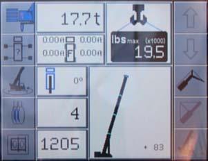
The main menu shows symbols for further submenus and symbols for current displays.
Refer to RCL Main Menu, page 3-75.
Registers the brightness of the operating environment. The brightness of all displays are automatically adjusted.

Refer to Adjusting the Brightness of the Display, page 3-57 to manually set the minimum brightness.
• Flashing: New warning message or error has occurred
• On: Error acknowledged, but still present
• Off: No warning message or error present
The function of buttons F1 to F14 is shown on the symbol next to or above the button. After the button is pressed and released, the function displayed is executed.
Registers the brightness of the operating environment. The brightness of all displays are automatically adjusted.
Refer to Adjusting the Brightness of the Display, page 3-57 to manually set the minimum brightness.
The lamp (1) lights up or flashes. Press the button once to open the Error Submenu.
The error submenu is where you access and acknowledge any errors that are present.
Refer to Error Submenu, page 3-101.
The lamp (1) lights up. Press the button once to close the current submenu, the menu from the next level up opens.
Input mode is deactivated.
The lamp (1) lights up.
Press the button once: buzzer tone off, error message acknowledged.
• Flashing: Crane capacity at 90 to 100%: buzzer tone on

• On: Crane capacity about 100%: buzzer tone on, machine shuts down. Refer to RCL Shutdown, page 3-72.
• Off: Crane capacity 0 to 90% For more information refer to RCL Early Warning, page 3-72.