F-code
Section
C-code
PS Chassis
S0.1
0000
Version no
T-code
002
395/396/397/398/399
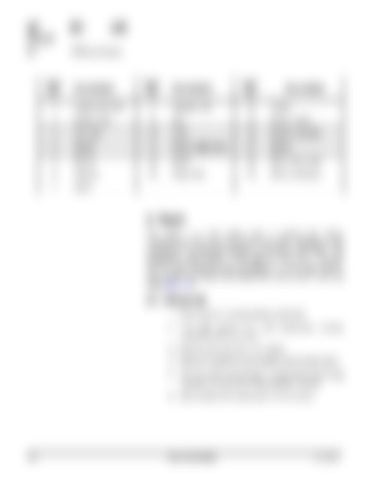
Item No.
Description
Item No.
Description
Item No.
Description
1
Panel, left hand
8
Washer, flat
14
Screw
2
Panel, side
9
Nut
15
Panel, cover
3
Grill, fan
10
Door
16
Mount, console
4
Screw
11
Panel, right hand
17
Screw
5
Screw
12
Dash
18
Plate, heat sink
6
Washer
13
Plug, hole
19
Plate, contactor
7
Latch
2. Dash The dash is a one piece unit. It covers the motor compartment, the drive and pump transistor regulators, and contactors. The operator display is mounted on the dash. The emergency stop switch is mounted on the truck. The key switch, travel speed/directional selector, lift and lower switch, horn switch, tilt switch and sideshifter switch are in the pod (see page 107).
2.1. Removal 1. Park truck on a level surface and block. 2. Turn key switch OFF and disconnect battery connector from the truck. 3. Remove the pod from the mount. 4. Remove hardware securing the dash to the frame. 5. Lift the cover up enough to disconnect the wiring harness connections to the operator display. 6. Lift the dash off removing it from the truck.
100
Return
Master Service Manual
2001-09-20


