3 minute read
Transistor Controller Replacement

from BT Electric Electrical Stand-Up Rider Truck RRX35/45 RDX30 RSX40/50 Master Service Manual 306756-000

F-code Section C-code PS S5.15 5710 Main Electronic Card
Version no T-code 001 395/396/397/398/399
Advertisement
2. Transistor Controller Replacement
NOTE! To determine the software version on the truck, turn the key switch ON. Software version is shown on the dash display at the initial power up. For truck serial numbers 28126001 - 31155000, when the transistor controller is replaced the logic chip in the A5 logic card needs to be updated to the P5-07 software. To up date the logic card proceed as follows: 1.Record all current parameter settings of the A5 logic card. 2.Turn key switch OFF and disconnect battery connector from the truck.
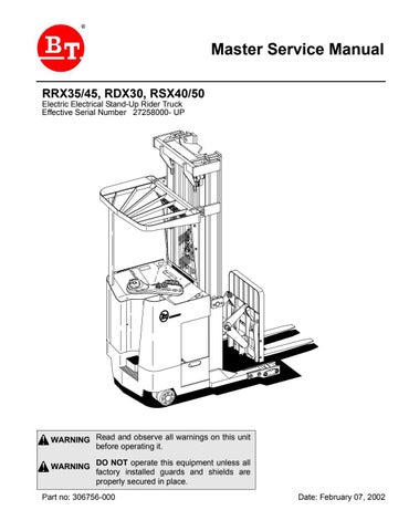
Two allen bolts holding A5 logic card to the frame.
Four screws holding cover on A5 logic card. Cut warranty seals to gain internal access to the A5 logic card.
3.Remove the driver’s compartment right side panel (exposing the A5 logic card) by loosening the lower two allen 0.19 inch (5mm) bolts. Remove the upper
F-code Section C-code PS S5.15 5710 Main Electronic Card
Version no T-code 001 395/396/397/398/399
two allen bolts. Carefully pull the panel towards the centerline of the truck and lift. Set the panel aside. 4.Remove the two lower screws holding the aluminum cover on the A5 card. 5.Remove two 0.19 inch (5mm) bolts holding the A5 card to the frame at the top of the A5 card. 6.Carefully tip the A5 card toward the centerline of the truck far enough to allow access to the two screws holding the aluminum cover on the card and remove cover.
NOTE! Cutting the warranty seals will not affect applicable product warranty. 7.Cut the Warranty Seals and remove the aluminum cover. 8.Install one of the top allen bolts to hold the A5 card in place while changing the logic chip.
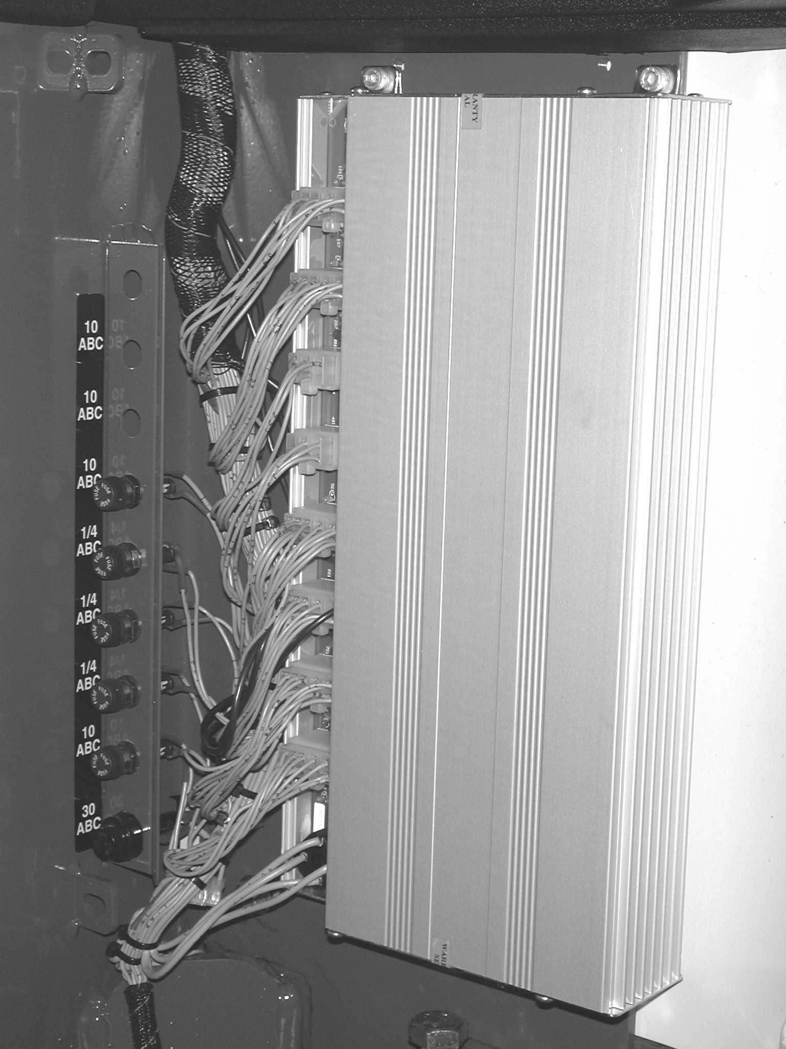
Logic chip extractor tool. Alligator clip on the end of the static strap.
Wrist strap on the end of the static strap.
9.Attach static strap to the wrist of the working hand and then to the A5 card frame.
F-code Section C-code PS S5.15 5710 Main Electronic Card
Version no T-code 001 395/396/397/398/399
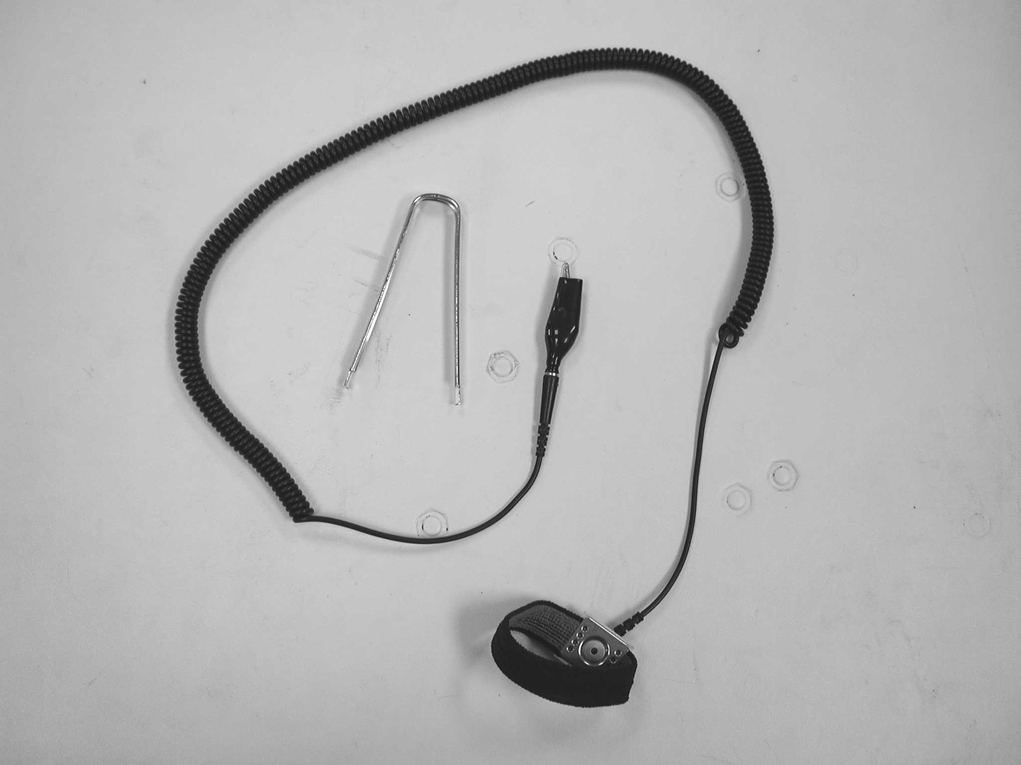
A5 logic chip to be removed and replaced.
When installing the cover on the A5 logic card be careful not to damage or bend these three components.
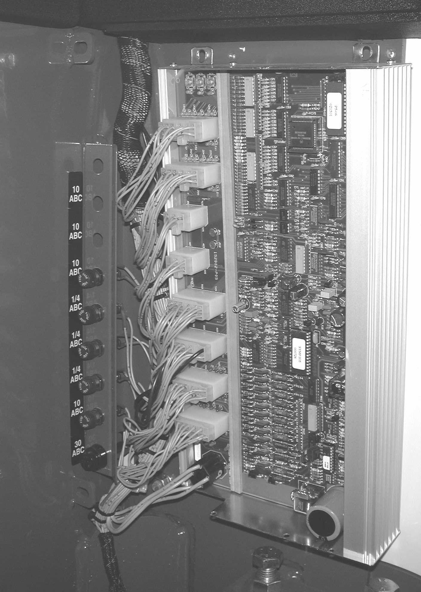
Attach alligator clip from static strap to A5 logic card here.
NOTE! When removing the logic chip, be careful to grasp only the logic chip and not the chip socket with the extraction tool.
10.Using the chip removal tool carefully remove the chip and set aside. 11.Carefully remove the new logic chip from its container. 12.Install the new chip with the notch in the chip located toward the top of the A5 card in the lower
F-code Section C-code PS S5.15 5710 Main Electronic Card
Version no T-code 001 395/396/397/398/399
socket holes (at the top of the new chip there should be four socket holes visible on each side).
NOTE! Be sure to carefully align the logic chip pins with the socket holes to ensure no logic chip pins are bent during installation.
NOTE! When installing the cover on the A5 logic card be carefully not to damage or bend components on the A5 logic board. 13.Remove the static strap from the A5 card. Install the aluminum cover on the A5 logic card. 14.Install lower two screws into the cover of the A5 card. 15.Remove the top allen 0.19 inch (5 mm) bolt from the A5 card. Tip the A5 card outward far enough to allow the two screws to be installed.
NOTE! Make sure the wiring harness is not caught behind the A5 card before tightening. 16.Install top two allen (5 mm) bolts to hold the A5 card in place. 17.Install the driver’s compartment right side panel and tighten. 18.Connect battery connector to truck and power truck up. 19.Using the values recorded at the beginning of this procedure set the truck’s parameters as noted. 20.Ensure proper operation of the truck before returning the truck to service.