6.
CAUTION BE SURE to exercise the MANDATORY SAFETY SHUTDOWN PROCEDURE (page 8) BEFORE proceeding. 1.
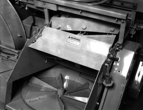
The space between the Cutterbar and Scraper will first have to be cleaned of debris. Then, move the Cutterbar forward to the end of its adjustment slots.
2.
After implementing the proper precautions, remove the Spinner and Cylinder Covers. For better access, remove the (4) Bolts holding the Sidesheet Tie and remove the Tie.
3.
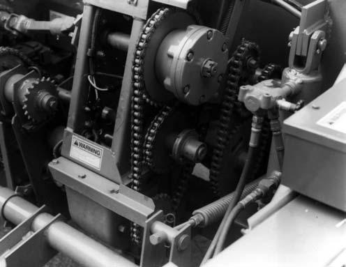
After the Screen (if present) is also removed, loosen the (3) Bolts which secure the Knife to the Cylinder Headers.
Adjust the Cutterbar and Knives following the details given in the Adjustment chapter of this manual.
NOTE: BE SURE to watch the balancing of the Cutting Cylinder Knives when mixing old and new Knives. An old Knife should ALWAYS be balanced on the opposite side of the Cylinder with another old Knife and a new Knife should ALWAYS be balanced on the opposite side with another new Knife.
SPOUT (Fig. 64) A replaceable Liner is built into the Spout which can be removed by taking-out (8) Plow Bolts. After the hardware is removed, the Liner can be guided through the Spout and removed from the Cap end, without taking the Spout off the Blower Outlet. To facilitate removal, it may be necessary to temporarily remove a Horizontal Spout Extension, if present. New Liner installation is in reverse of old Liner removal. As necessary, remove any or all of the Cleanout Hole Covers for access to the Liner and Plow Bolts.
2
2
1 1
3 3 4
5 4
1 – Sidesheet Tie 2 – Knife Bolt (1 of 3 per Knife) 3 – Cylinder Header (1 of 3)
6
Fig. 63
4.
Secure the replacement Knife to the Cylinder Headers with the (3) Knife Bolts. Torque each Bolt to 220 to 240 ft-lb.
NOTE:
Knife Bolts are threaded into Special Nuts which are positioned in the Header slots with their thin sides facing the left side of the Harvester. 5.
64
After the Knives and Cutterbar are adjusted, replace the Sidesheet Tie following details under the Cylinder Cover subtopic in this chapter.
7 1 – Liner 2 – Cap 3 – Spout 4 – Cleanout Cover 5 – 5/16 x3/4 Plow Bolt (6 Total) 6 – 5/16 x 1 Plow Bolt (2 Total) 7 – Attaching Hardware
Fig. 64: Spout and Wear Liner Assembly