9 minute read
CHAPTER 15 OPTIONAL FEATURES & ACCESSORIES

Most of the optional features & accessories, listed in this chapter, are covered by information listed in the Set-up & Assembly chapter. Some accessories are shipped with separate instructions to install. Refer to your Gehl “Farm Equipment Suggested List Prices” for stock numbers and ordering information.
AXLES, WHEELS & TIRES
The Harvester can be obtained with several choices of Axles, Wheels and Tires. The various choices are:
1.Standard Axle Set with Hubs and 14 x 8.00 D.C. Wheels (less Tires) - set of two
2.Standard Axle Set with Hubs and 14 x 8.00 D.C.
Wheels and 11L x 14 6–ply rating Implement
Tires - set of two
3.Standard Axle Set with Hubs and 15 x 10.00 D.C.
Wheels (less Tires) - set of two
4.Standard Axle Set with Hubs, 15 x 10.00 D.C.
Wheels and 12.5L x 15 8-ply rating Implement
Tires - set of two
5.Flotation Axle Set with Hubs, W11C x 16.1
Wheels and 16.5L x 16.1 8-ply rating Implement
Tires - set of two
6.Tandem Axle Set with Hubs, 15 x 8.00 D.C.
Wheels and 27 x 9.50 x 15, 6-Ply Rating Implement Tires - set of four
Blower Rim Sheet Liner
The Harvester is designed with a replaceable Wear Liner for the Blower Rim Sheet. A replacement Liner is available by part number 094948. Instructions for installation are included with the Kit of parts.
Control Box Extension Harness
A Control Harness Extension is available, if the Control Harness can NOT reach the Control Box. It is installed between the Control Box and the Control Harness. Installation information is provided in the Set-up & Assembly chapter.
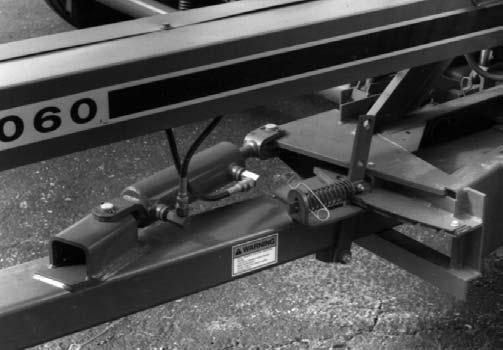
Hydraulic Tongue Kit
A Hydraulic Tongue Kit is available to remotely adjust the Tongue position from the tractor seat. The Kit contains a standard double-acting 8″ stroke, 3″ bore Cylinder, two (2) Hose assemblies, two (2) Cylinder Anchor Pins, four (4) Cotter Pins, two (2) Hose Guards, two (2) Swivel Adapter Unions, a Notch Cover and appropriate attaching hardware. Mounting details are provided in the Set-up & Assembly chapter. This Kit requires a second pair of tractor hydraulic outlets.
LENGTH-OF-CUT KITS
The Harvester is designed and provided with changeable Length-of-Cut (LOC) Sprockets. A 25 Tooth (1/4 LOC) is provided on the Feed Roll Transmission. Other Lengths-of-Cut can be obtained by ordering a 20 Tooth (3/16″ LOC), a 30 Tooth (5/16″ LOC), or a 37 Tooth (3/8″ LOC) Sprocket.
Long Cut Kit
A Long Cut Kit is available to provide a 9/16″ Length-of-Cut by replacing the factory-provided Sprockets on the Feed Roll Drive Transmission Input Shaft and the Attachment Drive Shaft. Both Sprockets are secured to their respective Shafts with two SHSS each.
Main Drive Impact Pins
Replacement 5/16 x 3–1/4, Grade 5 Impact Pins and Hexagon Nuts are available by GEHL part number 080699. One package contains eight Bolts and sixteen Nuts.
Offset Wagon Hitch
An Offset Wagon Hitch is available to reposition the Hitchplate so that the forage box pulls more directly behind the tractor when harvesting row crops. This reduces side draft in muddy fields, so that the Harvester can stay on the rows. Installation instructions are provided with the package of parts.
Safety Chain
NOTE: If the Harvester is going to be transported on a public highway, a Safety Chain should be obtained and installed per details in the Transporting chapter.
A 30,000 pound Safety Chain Kit is available to accommodate the potential weight of the Harvester and a forage box.

SCREENS & COMPONENTS Screen Cam Kit
A Screen Cam Kit MUST be ordered separately for mounting a Screen or the Wet Crop Spout. The Kit contains six (6) Cams and Cam mounting hardware.
Square-hole Screens
Numerous Square-holed Screens are available to match a variety of length-of-cut requirements in different crops. Reversible Screens are available in 4″, 3″, 2″ , 1-1/2″, 1-1/4″, 1″ and 3/4″ sizes. Refer to the Set-up & Assembly chapter for positioning details. For mounting, order and use a Screen Cam Kit.
Second Tractor Control Box Wiring Kit
A Second Tractor Control Box Wiring Kit is available for adapting the same Control Box to a second tractor. Installation information is provided in the Set-up & Assembly chapter.
Shear Bolts
Additional Shear Bolts are available in packaged quantities of eight (8) per package, as required. Order Shear Bolts by the following numbers:
Order
NumberDescription
095139(8) 5/16 x 1 Gr. 2 (Carriage Bolts)
Spinner Shear Bolts & (8) 5/16
Hexagon Lock Nuts
080079(8) 1/4 x 1-1/2 Gr. 8 Feed Roll Shear
Bolts & (8) 1/4 Hexagon Lock Nuts
SPOUT EXTENSIONS & COMPONENTS
The Harvester is shipped from the factory with a 1-ft
Vertical Spout Extension factory-installed onto the Blower Outlet. This enables factory-installation of both the Spout and Cap Control Motors. Several Kits are available singly or in combination for relocating the effective position of the Cap, higher, lower or farther away from the Blower Outlet. The following information defines the various Kits which are available:
Cap Motor Relocation Kit (Fig. 129)
If the Cap is too high for the forage box being used and it becomes desirable to lower the Cap by removing the factory-installed 1-foot Vertical Extension, a Cap Motor Relocation Kit MUST be obtained separately. The Relocation Kit contains an Actuator Support Bracket and a Wire Harness Loom. Installation instructions are provided with the Kit of parts.
Horizontal Extensions
Horizontal Spout Extensions are available in 3-1/2-foot and 5–1/2-foot lengths. Both Kits contain all of the same components and the appropriate 3-1/2-foot and 5-1/2 foot long Extension. These same components are: a Tie Plate and attaching hardware and a Tripod Kit. The Tripod Kit is also available separately.
Tripod Kit
The Spout Tripod Kit is supplied with either Horizontal Spout Extension package or available separately when additional Spout Support is desired or needed.
Vertical Extensions
Vertical Spout Extensions are available in 1-foot and 2-foot sizes. A maximum of 4 feet of vertical Extensions can be installed. A Tripod Kit is required when a total of more than 2 feet of Vertical Extensions is installed.
NOTE: A Kit is also available to relocate the Cap Control Motor when the original factory-installed 1-foot Vertical Extension is removed. Refer to the Cap Motor Relocation Kit topic for additional information.
Spout Liner
The Harvester is designed with a replaceable Wear Liner for the Spout. A replacement Liner is available by part number 112182. Installation details are provided in the Service chapter.
Telescoping Pto Drives
The Harvester can be ordered and obtained with either a 1-3/8 or a 1-3/4 Telescoping PTO Drive. The 1-3/4 Drive also includes a Drawbar Extension for relocating the Hitch Clips. Mounting details are provided in the Set-up & Assembly chapter.
Transport Lighting Kit
NOTE: If the Harvester is going to be transported on a public highway, a Transport Lighting Kit should be obtained and installed per details provided in the Kit.
An accessory Highway Transport Lighting Kit is available for all Harvester models. It includes Lights, Wiring Harnesses, an Outlet, and installation instruc- tions. The Outlet allows connecting the Transport Lights of a wagon towed behind the Harvester.
Tunnel Switch Kit
A Shear Bolt model Harvester can be equipped with a Tunnel Switch Kit for activating a Water System.
NOTE: The Tunnel Switch Kit functions as a sensing element for the Water System. In addition, a Water Tank Kit, for the Hay Attachment, MUST also be ordered separately and installed on the Attachment.
The Tunnel Switch assembly is designed for installation in the Spinner Chute to detect the presence of material flow through the Tunnel and then provide a Switch Contact change signal to the Water Tank System. The Tunnel Switch Kit includes the Tunnel Switch, a Tunnel Adapter Harness, a Tunnel Vane, and mounting hardware. Installation details are provided in the Set-up & Assembly chapter.
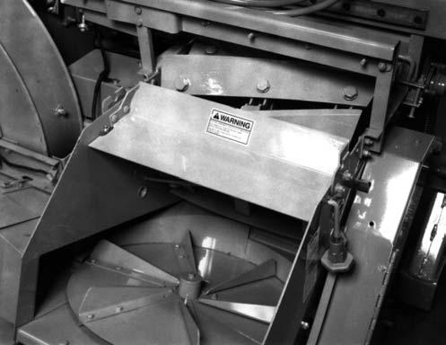
Wet Crop Deflector
A Wet Crop Deflector is available for installation on the Harvester in the area of the Spinner Disc. It is designed for use when harvesting extremely wet, low fibrous materials which tend to stick to the walls and the Spinner Cover and then, fall-off as a mass which causes plugging in the Spinner Chute. For mounting the Deflector, a Screen Cam Kit, which is the same as for mounting Screens, MUST be ordered separately. Mounting details are given in the Set–up & Assembly chapter along with the Screen installation information.
NOTE: When a Wet Crop Deflector is installed, a Screen can NOT be used.
Chapter 16 Decal Locations
General Information Caution
ALWAYS read and abide by the Safety Rules and information shown on Decals. If Decal(s) become(s) damaged, unreadable or if the unit is repainted, the Decal(s) MUST be replaced. If repainting, MAKE SURE ALL Decals which apply to your machine are properly affixed to your unit in their proper locations.
Decal Locations information is provided to assist in the proper selection and application of new decals, in the event the original decal(s) become(s) damaged or the machine is repainted.
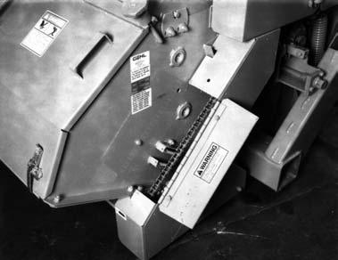
For correct replacement of decal(s), compare the close-up location photographs to your machine BEFORE starting to refinish the unit. Check-off each required decal using the illustration reference number to find the part number, description and quantity in the list. Refer to the appropriate illustration(s) for replacement location(s).
NOTE: Refer to the SAFETY Chapter of the Operator’s Manual for the specific information provided on all of the various Safety Decals.
Paint Notice
Use this list to order paint for refinishing:
901225One Gallon Blaze Paint
901226One Gallon Maize Paint
6102396 (12 oz. Spray Cans) BIaze Paint
6102406 (12 oz. Spray Cans) Maize Paint
New Decal Application
Surfaces MUST be free from dirt, dust, grease and other foreign material before applying the new decal. To apply a solid-formed decal, remove the smaller portion of the decal backing paper and apply this part of the exposed adhesive backing to the clean surface while maintaining proper position and alignment. Slowly peel off the other portion of the backing paper while applying hand pressure to smooth-out the decal surface. To apply a die-cut Decal, first remove the backing paper. Then, properly position the Decal onto the clean mounting surface. After the Decal is firmly applied and smoothly pressed-down, remove the front covering paper.
The Decal Set for the 1060 Forage Harvester is 093440
The Set includes the following:
Ref.Part
No.No.Description & Quantity
1065269Knife Sharpener Operating Instructions
2067493Reflector/Red (2 Places)
3093211Cutterbar Removal & Replacement
40730851000 RPM ONLY (Early Style)
- NOT Shown
50772231060 (Vertical)
6074707Length Of Cut Chart
7075808Decorative Stripe
8076166Decorative Gehl
9075835Drawbar Clip Setup (Before SN6186)
- NOT Shown
10075837Stripe Point
11077215Wiring Diagram (Before SN8501)
- NOT Shown
12093212Cutterbar Adjustment
13077745Speed Monitor Plug (Before SN8501)
- NOT Shown
140781071060 (Horizontal)
15078251Maximum Tractor Horsepower
16076165Decorative Gehl (Rear)
17078676Metal Stop
18078742AUTO–MAX
19112204Wiring Diagram (Inside Torque Sensor Control Box) (After SN8500)
078810Wiring Diagram (Inside Torque Sensor Control Box) (Before SN8501)
- NOT Shown
20078837Wiring Diagram (Inside Light Box)
21080247NO Step
22093730Shear Bolt (After SN6700)
088328Shear Bolt (After SN5725 & Before SN6701) - NOT Shown
083003Shear Bolt (After SN5405 & Before SN5726) - NOT Shown
080694Shear Bolt (Before SN5406)
- NOT Shown
23091444DANGER - Rotating Drive Line
24093020Lubrication Symbol (12 Places)
25093202DANGER - Avoid Electrocution
26093204WARNING - Remove PTO BEFORE Sharpening Knives
27093210Patent (Forage Harvesters)
28093213Speed Monitor Terminations (Before SN8501) - NOT Shown
29093365WARNING - Close or Replace Guard (4 Places)
30093366IMPORTANT - Store Manual Here
31093367WARNING - Owner’s Responsibility & Read Manual
32093373WARNING - General Safety
33093374WARNING - Towing Implement Without Brakes
34093376WARNING - Keep Hands Out
35093378DANGER - Rotating Components (4* Places)
36093379WARNING - Wear Goggles When Using Knife Sharpener
37093380WARNING - 1–3/4″ PTO Shaft Restriction
38093381WARNING - Use Drawbar Transport Lock

39093436WARNING - Use Locking Hitchpin (Before SN8501) - NOT Shown
40093442Feed Roll Height Indicator (Before SN8501) - NOT Shown
41093465WARNING - 1000 RPM Operation Only
42093653WARNING - Rotating PTO Shield

43093439WARNING - Shear Bolt Model Control Box Operation


* (1 -NOT Shown) Supplied for Early 2-ft Vertical Deflector Extension
NOTE: This list is a repeat of the Decal List on a previous page and is provided for your convenience when selecting Decals from the second page of photographs.
The Decal Set for the 1060 Forage Harvester is 093440 The Set includes the following:
Ref.Part
No.No.Description & Quantity
1065269Knife Sharpener Operating Instructions
2067493Reflector/Red (2 Places)
3093211Cutterbar Removal & Replacement
40730851000 RPM ONLY (Early Style) - NOT Shown
50772231060 (Vertical)
6074707Length Of Cut Chart
7075808Decorative Stripe
8076166Decorative Gehl
9075835Drawbar Clip Setup (Before SN6186) - NOT Shown
10075837Stripe Point
11077215Wiring Diagram (Before SN8501) - NOT Shown
12093212Cutterbar Adjustment
13077745Speed Monitor Plug (Before SN8501) - NOT Shown
140781071060 (Horizontal)
15078251Maximum Tractor Horsepower
16076165Decorative Gehl (Rear)
17078676Metal Stop
18078742AUTO–MAX
19112204Wiring Diagram (Inside Torque Sensor Control Box) (After SN8500)
078810Wiring Diagram (Inside Torque Sensor Control Box) (Before SN8501) - NOT Shown
20078837Wiring Diagram (Inside Light Box)
21080247NO Step
22093730Shear Bolt (After SN6700)
088328Shear Bolt (After SN5725 & Before SN6701) - NOT Shown
083003Shear Bolt (After SN5405 & Before SN5726) - NOT Shown
080694Shear Bolt (Before SN5406) - NOT Shown
23091444DANGER - Rotating Drive Line
24093020Lubrication Symbol (12 Places)
25093202DANGER - Avoid Electrocution
26093204WARNING - Remove PTO BEFORE Sharpening Knives
27093210Patent (Forage Harvesters)
28093213Speed Monitor Terminations (Before SN8501) - NOT Shown
29093365WARNING - Close or Replace Guard (4 Places)
30093366IMPORTANT - Store Manual Here
31093367WARNING - Owner’s Responsibility & Read Manual
32093373WARNING - General Safety
33093374WARNING - Towing Implement Without Brakes
34093376WARNING - Keep Hands Out
35093378DANGER - Rotating Components (4* Places)
36093379WARNING - Wear Goggles When Using Knife Sharpener
37093380WARNING - 1–3/4″ PTO Shaft Restriction
38093381WARNING - Use Drawbar Transport Lock
39093436WARNING - Use Locking Hitchpin (Before SN8501) - NOT Shown
40093442Feed Roll Height Indicator (Before SN8501) - NOT Shown
41093465WARNING - 1000 RPM Operation Only
42093653WARNING - Rotating PTO Shield
43093439WARNING - Shear Bolt Model Control Box Operation
* (1 -NOT Shown) Supplied for Early 2-ft Vertical Deflector Extension