39 minute read
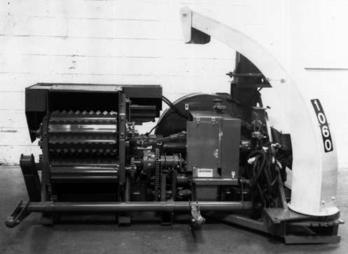
HARVESTER WITH SHEAR BOLT-PROTECTED FEED ROLL & ATTACHMENT DRIVES

OPERATING FEED ROLLS & ATTACHMENT (Fig. 17)
The Electric Clutch and Shifter Transmission combination is used to stop the Feed Rolls and the Attachment, to run them forward (to bring the crop into the Cutting Cylinder) or, to run the Feed Rolls backwards (to reverse plugged material back out of the Cutting Cylinder area). Shifting the Transmission is accomplished by appropriate activations and settings of Switches on the Control Box which is mounted on the tractor.
To feed material into the Harvester, set the Feed Roll toggle Switch to the “Forward” position. The Transmission will continue operating in the “Forward” mode until the Feed Roll Toggle Switch is reset to the “Off” position.
To stop the Feed Rolls and the Attachment, turn off the power to the system by placing the Feed Roll Toggle Switch to the “Off” position.
Caution
BEFORE leaving the tractor, ALWAYS turn Control Box Power Keyswitch OFF and remove the Key and take it with you for your own safety and to avoid unnecessary drain on your tractor battery.
exceeds 6″ (152 mm) or if an obstruction gets between the Feed Rolls, the Shear Bolt in Upper Feed Roll Drive will shear and thus stop Feed Roll operation and the crop will NOT feed into the Cutting Cylinder.
If the Shear Bolt has failed, it is possible to reverse the plugging material out of the Feed Roll area by idling the tractor and shifting the Feed Roll Drive Transmission into reverse.
NOTE: Upper Feed Roll Drive is protected by a One-way Shear Bolt Protective Device. This mechanism allows the Drive to be reversed before installing a new Shear Bolt. The Shear Bolt holes will self-align, when the Feed Rolls are reversed.
OVERLOAD PROTECTION (Fig. 16)
To back material out of the Feed Rolls and Attachment, set the Feed Roll Control Toggle Switch to the “Reverse” position and hold it there momentarily while observing the crop as it reverses-out of the Feed Rolls and Attachment; this process should only take 3 to 4 seconds. If the “Reverse” position is held continuously for more than 12 seconds, the Circuit Breaker will trip-out to protect the Shifting Solenoid. To reset the Breaker, wait at least 10 seconds and then, depress the Button to reset the Breaker.
Unplugging The Feed Rolls
By design, the Feed Rolls allow various mat thicknesses to pass between them. If however, the mat thickness
The Upper Feed Roll Drive is protected by a One-way Shear Bolt Protective Device. The Protective Device allows the Feed Rolls to be reversed without having to first replace the sheared Bolt. The Shear Device uses a 1/4 x 1-1/2 Grade 8 Shear Bolt. To install a replacement Bolt, BE SURE to first idle the tractor and then reverse the Feed Roll Transmission to align the mounting holes in the Protective Device. Additional Shear Bolts are provided in the Toolbox.
Move the “AUTO-OFF-MANUAL” Mode Switch to “AUTO” and leave it there. With the Power Keyswitch ON, the Feed Rolls and Attachment are controlled by the FEED ROLLS & ATTACHMENT “SELECTOR” Switch. Toggling the Switch to “FWD” (forward) will
immediately cause the Electric Clutch to close and, if the PTO is engaged, the Feed Rolls and Attachment will run to feed crop into the Knives. Toggling into “NEUTRAL” will open the Clutch and stop all Feed Roll and Attachment motion. To back material out of the Harvester, move the Toggle Switch to “REV” (reverse) and, in addition, rotate and hold the springloaded “HOLD FOR REVERSE” Handle to the right (counterclockwise); release the Handle to automatically open the Clutch and stop reversing.
The reversing process should only take 3 or 4 seconds. If the “Hold-to-Reverse” Switch is continuously held for more than 12 seconds, the Circuit Breaker will trip-out to protect the Shifting Solenoid. To reset the Breaker, wait at least 10 seconds and then, depress the Button to reset the Breaker.
NOTE: Except for the brief time that the “HOLD FOR REVERSE” Handle is activated, gearing in the Transmission is always in the Forward condition. It has NO neutral. The Neutral condition is created solely by opening the Electric Clutch.
The “MANUAL” and “OFF” positions of the Mode Switch are used only when there is a problem with the Automatic circuit. In this mode, the Clutch closes and runs the Feed Rolls and Attachment Forward, when the Switch is toggled to “MANUAL” and the Clutch opens when the Switch is toggled to “OFF” to stop Feed Rolls and Attachment. While operating in MANUAL condition, there is NO Reverse capability NOR will the Speed Monitor, Metal Stop system or Torque Sensors operate.

Caution
BEFORE leaving the tractor, ALWAYS turn the Control Box Power Keyswitch to OFF, remove the Key and take it with you for your own safety and to avoid unnecessary drain on your tractor battery. If any of the Control Box Indicators are still “ON” (lighted), the Keyswitch is NOT off.
NOTE: When operating in the “MANUAL” mode, be extra cautious to avoid plugging the Feed Rolls or the Attachment because the reversing function is inoperative in this mode.
CONTROL BOX (Figs. 18 & 19)
Place the “Auto-Manual” Switch into the “Auto” position and LEAVE IT THERE. This will allow the Auto-Max system to protect the Harvester. No AutoMax Shut-Off systems will operate with the “AutoManual” Switch in “Manual”. The “Manual” Switch position allows the Feed Roll and attachment Drive Load Sensors to ratchet when they are overloaded. The Load Sensors may ratchet only a few seconds at a time, but the total accumulative ratcheting life is less than 7 minutes. The “Manual” Switch position should be used as little as possible to avoid damaging the Load Sensors. The Load Sensors should never ratchet while the “Auto-Manual” Switch is in “Auto”.
If the Metal Stop system malfunctions and can NOT be repaired immediately, disconnect the Wiring Harness Plug inside the Feed Roll Drive Frame, move the Stop Pawl Spring to the “bypass” position, and keep the “Auto-Manual” switch in “Auto”. Refer to the Metal Stop section in this chapter.
Switch to “Off”. The “Manual” Switch position should only be used as a means to finish the day’s work before making repairs. DO NOT use “Manual” Switch all season long.
Unplugging The Feed Rolls
By design, the Feed Rolls allow various mat thicknesses to pass between them. If however, the mat thickness tries to exceed 6” (152 mm) or if an obstruction gets between the Feed Rolls, the Load Sensor will detect this condition. This will cause the Electric Clutch to open and stop Feed Roll operation and the crop will NOT feed into the Cutting Cylinder.
When an overload condition does occur, reset the Clutch by setting the Feed Roll & Attachment Selector Switch to NEUTRAL (center position) and then, return it to FWD (forward) position. Do NOT idle the tractor when shifting the Feed Rolls. If the overload condition is NOT cleared by merely resetting the Electric Clutch, move the Feed Roll & Attachment Selector Switch to the REV (reverse position) and rotate the HOLD-FOR-REVERSE Switch to reverse the material back out about 6” (152 mm). Then, reset the Feed Roll & Attachment Selector Switch to the FWD (Forward position).
NOTE: Special care should be taken so as NOT to reverse the crop too far. Corn should NOT be allowed to back-out past the Front Feed Rolls or it will NOT feed back in when the forward mode is re-engaged. Hay should be watched so that the Attachment Auger does NOT “auger” the material sideways and jam it into the Attachment Sidesheets; although it should NEVER need to be backed up that far.
Warning
NEVER attempt to hand feed crop into the Feed Rolls as the crop will feed faster than you can react to let go.
NOTE: Using electrician’s tape, cover the ends of the Plug and Socket to keep dirt out of both parts.
If the Speed Monitor system malfunctions and cannot be repaired immediately, disconnect the Speed Monitor Plug at the side the Spinner Gearbox and keep the “Auto-Manual” Switch in “Auto”.
If disconnecting the Metal Stop system and the Speed Monitor does NOT allow the Auto-Max system to operate and it can NOT be repaired immediately, proceed as follows. Operate Harvester with the “AutoManual” Switch in “Manual” and shut-off the Feed Rolls and Attachment by moving the “Auto-Manual”
Overload Protection
The Upper Feed Roll Drive and the Attachment Drive have Torque Sensors. The Torque Sensors close a Switch when the driving torque is too high. The Switch then disengages the Electric Clutch, stopping the Feed Rolls and Attachment. The Cutting Cylinder, Spinner, and Blower continue to operate to clean out cut material. When the Torque Sensor stops the intake of material, an Alarm Horn signals in the Control Box. The Alarm is turned off by moving the “FWD-NEUTRAL-REV”

Switch to NEUTRAL. This also resets the Electric Clutch so that FORWARD or REVERSE can be selected.
There is a Speed Monitor on the Spinner Gearbox. It measures the Harvester operating speed and closes a Switch if the speed is too low. The Switch disengages the Electric Clutch, stopping the Feed Rolls and Attachment. The Cutting Cylinder, Spinner, and Blower continue to operate to clean out cut material. The Speed Monitor sounds the Alarm Horn in the Control Box when it stops the Feed Rolls and Attachment. The Alarm is turned OFF by moving the “FWD-NEUTRAL-REV” Switch to NEUTRAL. This also resets the Electric Clutch so that FORWARD or REVERSE can be selected.
The Speed Monitor is controlled by the Tunnel Switch. The Tunnel Switch senses the flow of material in the Spinner Chute (Tunnel). If material is in the Tunnel, the Speed Monitor will shut OFF the Feed Rolls whenever the Harvester speed is too low (approximately 70% of operating speed). This helps prevent plugging in the Blower and Spinner. If the Tunnel has NO material in it, then the Speed Monitor is bypassed. This allows starting an empty Harvester at tractor idle speed.
Metal Detector Models Only
INTRODUCTION (Fig. 20)
NOTE: Metal Detector models contain all of the features included on the Torque Sensor models. Review all information in the section labeled “Harvester with Torque Sensor-protected Feed Roll and Attachment Drives” and the information in this Metal Detector section.
The Metal Detector model Harvester contains a Metal Stop system which is designed to prevent ferrous metal (containing iron) objects from entering the Forage Harvester Cutting Cylinder. It can be used with all mounted Attachments, except those which use a steel Cover over the Lower Front Feed Roll, such as the Snapper Attachment. A “bypass” procedure is provided for use with these Attachments.
When a ferrous metal object passes through the Magnetic Field over the Lower Front Feed Roll, a low voltage signal is sent to the Amplifier Box which is mounted on top of the Feed Roll Housing. When the signal reaches the Amplifier Box, an electrical contact is opened which, in turn, interrupts power to the Pawl Solenoid. The Feed Rolls are stopped immediately by the Stop Pawl. At the same time, the Electric Clutch opens to stop power to the Attachment and Feed Rolls.
When the Metal Stop system is functioning properly, the following ferrous metal objects can be detected: hitchpins scrap iron bolts wrenches rake teeth steel pipe steel fence posts plow points sickle sections chains nails wire rocks containing iron
Regardless of system adjustment, the following objects will NOT be detected: aluminum stainless steel wood tile cement stones
NOTE: The optimum performance of your Metal Stop system depends on it being kept in proper operating condition and properly maintained. Like any other electrical system, the Metal Stop system is subject to malfunction due to defects, occasional breakdowns, misuse and human error. As with any mechanical device, components can breakdown or wear. Therefore, it is highly recommended that the system be tested on a daily basis.
The Metal Stop system is only sensitive to moving objects; keep this in mind when performing the test procedures. There is also an area, at the center and the ends of the Lower Feed Roll, where sensitivity is reduced. Sensitivity also decreases as the distance from the object to the Lower Front Feed Roll increases.
During normal operation, a high detection rate is achieved because of the forces of gravity and the stirring action of the feeding mechanism which causes most of the ferrous metal objects to descend to the bottom of the incoming crop material.
As with all GEHL equipment, the Metal Stop system is initially warranted against defects in material and workmanship. However, because of the above described conditions, the Metal Stop system can NOT and MUST NOT be expected to be 100% effective at detecting iron objects.
General Information
(See Fig. 18)
The Metal Stop system is operated from the tractor seat with the Harvester Control Box. A ferrous metal detection causes the Amber Signal Light on the Harvester to “flash” and the Control Box Buzzer to sound.
NOTE: Sounding of the Control Box Buzzer also signals maximum capacity or “low speed”. The flashing Amber Light only signals for a metal detection. The Harvester can NOT be operated until after the Metal Stop system is reset.
To turn off the signaling devices, safely locate and remove the metal and, restore the detection system to be able to resume harvesting, perform the steps in the sequence given on the Control Box Decal or detailed in the Safety chapter.
SYSTEM START-UP (Figs. 21 & 22
& see Fig. 18)
To initially start-up the Metal Stop system or reset it, after metal has been detected and removed, perform the “Start-up or Reset Procedure” given, with the tractor PTO disengaged.
If the Amber Light on the Harvester does NOT go out and remain “off”, the Stop Pawl is probably stuck in the Ratchet Wheel., as shown in the illustration provided. When the Pawl sticks, it causes the Circuit Breaker , in the amplifier Box to open.
Wait about 10 to 15 seconds for the (heat activated) Breaker to cool. Then, idle the tractor, engage the PTO and reverse the Feed Rolls until the Rolls move. The Amber Light should go out and remain. “off”. Now, the Metal Stop system is ready to use. After the preceding steps are performed, idle the tractor and engage the PTO and start (resume) harvesting.
Action
Start-up or System Reset Procedure
Reason
1.Move Mode Switch to AUTO and leave it there. Metal Stop system does NOT operate with Mode Switch in MANual position. Refer to System Bypass topic in this chapter.
2.Move the FEED ROLL Switch to “Neutral”. If the Switch is in “Forward”, Buzzer will sound when Keyswitch is turned “ON”.
3.Turn Keyswitch “ON”. Control Box is energized and ready but, Amber Light goes “ON”.
4.Move the FEED ROLL Switch to “Reverse” position and momentarily activate the HOLD FOR REVERSE Switch (Harvester Amber Light will go off).
NOTE: The Harvester will NOT operate with the Control Box FEED ROLL Switch in the “Forward” position while the Amber Light on the Harvester is flashing. If, after attempting to reset the system, the Amber Light does NOT remain “OFF”, refer to appropriate information in the Troubleshooting chapter.
Stopping Harvester
The Harvester and Metal Stop system should be switched OFF when the Harvester is NOT being used. This will avoid unnecessary drain on the tractor battery. The following sequence should be carried-out to turn the system OFF:

Metal Stop system is set (reset) and ready for operation when the Amber Light is “OFF”.
1.Move the Control Box FEED ROLL Switch to the “Neutral” position.
2.Turn the Power Keyswitch to “OFF” and remove the Key before leaving the tractor seat.
Detection
When a ferrous metal detection occurs, the Solenoid will release the Spring-loaded Stop Pawl into the Ratchet Wheel. Simultaneously, the Electric Clutch will receive a signal to open and thus, immediately stop the Feed Rolls and Attachment.

Detection Reaction Procedure
Action Reason
1.Move FEED ROLL Switch to “Neutral”. This stops the Buzzer.
2.Stop forward travel and back-up the tractor. This separates crop in the Feed Rolls from the crop on the ground.
3.Reverse the Feed Rolls. This remove the crop (Containing the metal) from the Feed Rolls.
4.Shut-off the tractor PTO and engine. This keeps the Harvester from running unnecessarily.
5.Shut the Power Keyswitch OFF, remove the Key and take it with you.
To prevent undesired or unexpected system activation.
6.Wait for ALL parts to STOP moving. To avoid being injured by moving parts.
7.Remove the metal from the crop. This should be done with the portion of the crop, containing the metal, on the ground.
The preceding action also occurs when the Mode Selection Switch is turned “OFF” as well as when Power is interrupted to the Metal Stop system.
A ferrous metal detection is indicated by the Amber Light on the Harvester flashing and the Control Box Buzzer sounding. If the Amber Light is NOT flashing, the Control Box Buzzer is indicating a Load Sensor or Speed Monitor activation..
When a ferrous metal detection occurs, carry-out the procedure detailed in the “Detection Reaction Procedure” given.
Warning
BEFORE searching for detected metal, exercise the MANDATORY SAFETY SHUTDOWN PROCEDURE (page 8). REMEMBER also that, when PTO is engaged, Cylinder and Blower continue to rotate when Feed Rolls and Attachment are stopped.
The ferrous metal object will usually be within 1 foot of the end of the crop which was about to enter the Cutting Cylinder. If the metal object can NOT be discovered through an initial search, continue the search after exercising the proper precautions in the following manner: a.Stop forward travel and back-up the tractor b.Reverse the Feed Rolls c.Shut off the tractor PTO and engine d.Shut the Power Keyswitch “Off”, remove the Key and take it with you e.Wait for ALL parts to stop moving f.Remove the metal from the crop
1.Take the hay that was reversed-out of the Hay Attachment and spread it onto the ground in front of the Attachment.
2.With NO one near the Harvester, reset the Metal Detector system and start-up the Harvester. Slowly move forward and harvest the windrow.
3.The ferrous metal object will be detected a second time.
4.Repeat the following standard procedure to remove the metal.
Warning
NEVER attempt to hand feed crop into the Feed Rolls as the crop will feed faster than you can react to let go.
Making a hand-made windrow and driving slowly into it should drastically reduce the amount of material that has to be searched. The small amount of material going into the Feed Rolls should also make the second detection more likely to occur.
However, it is possible that the metal object stayed on the ground when harvesting the hand-made windrow or during the search.
The Metal Detector system resets itself when the Feed Rolls are reversed to remove the detected ferrous metal. The Metal Stop system sometimes may also detect metal while the Feed Rolls are being run in reverse. This type of metal detection will cause the Amber Light, on top of the Harvester Feed Roll Drive Frame, to continue flashing. Reset the system by shifting to reverse to make the Light go off.

tion” mode cancels ALL automatic Shut-off Devices of the Harvester’s electrical system, including the Metal Stop system. Furthermore, the system can NOT be used on an Attachment using a steel Cover over the Lower Front Feed Roll, such as the Snapper Attachment.
It may be desirable or otherwise necessary to bypass the Metal Stop system for the reasons mentioned in the previous paragraph or, if a malfunction occurs that can NOT be remedied quickly. After the Metal Detector system is bypassed, the Harvester can be operated in the same manner as a unit without the Metal Detector system. Bypassing the system allows you to operate in either the “OFF-MANual” or “AUTOmatic” mode and, if desired, use a Snapper Attachment.
Reasons Why
The Metal Detector system can NOT be used with the Harvester Control Box Mode Selector Switch in the “OFF-MANual” position. The “OFF-MANual” posi-

Procedure
To bypass the Metal Detector system, refer to the illustrations provided and proceed as follows:
1.Move the Pawl Spring from the “Operating” position to the “bypassed” position, as shown. After the Spring is moved, make sure that the Stop Pawl is away from the Ratchet Wheel.
2.Disconnect the Plug inside the Feed Roll Drive Frame, as shown. Using electrical tape, cover the ends of the Plugs to keep dirt out of the Plug sockets. Also, fasten disconnected Plugs where they can NOT rub on Upper Feed Roll Drive Shaft.
To restore the Metal Detector system, return the Spring and Plugs to their original operating positions and return the Control Box Switch to the “AUTOmatic” mode.
DAILY SYSTEM INSPECTIONS (See Fig. 18 & 21)
Since the Metal Stop System is factory installed, the unit has been checked-out for proper operation before leaving the factory. The following inspections should be made on a periodic basis to maintain proper operation:
1.Check the Wiring Harnesses, Wires and Plugs to determine their condition and electrical continuity.
2.Check the Stop Solenoid for correct adjustment and proper Ring alignment.
3.Check that the Metal Stop System is operating properly by carrying-out the following “System Test” procedures.
System Test Caution
BEFORE proceeding to perform any test or adjustment on the Metal Detector Stop system, exercise the MANDATORY SAFETY SHUTDOWN PROCEDURE (page 8).
1.With the Mode Switch in “AUTOmatic”: a.Move the FEED ROLL Switch to “NEUTRAL”. b.Turn Control Box Keyswitch “ON”. c.Move the FEED ROLL Selector Switch to the “REVERSE” position and momentarily activate the “HOLD FOR REVERSE” Switch. Harvester Amber Light will go off unless the Pawl is stuck in the Ratchet Wheel. d.Move the FEED ROLL Selector Switch to the “FORWARD” position. e.Pass a ferrous metal object between the Upper and Lower Front Feed Rolls (the Solenoid should release the Stop Pawl into the Ratchet Wheel, the Amber Light should flash and, the Control Box Buzzer should sound signifying a metal detection).
2.If the Pawl is stuck in the Ratchet Wheel or the system fails to operate in the manner described, refer to the Troubleshooting chapter, of this manual, to determine the cause and remedy for the problem(s).
Chapter 7 Adjustments Caution
BEFORE proceeding to perform any adjustments on this unit, exercise the MANDATORY SAFETY SHUTDOWN PROCEDURE (page 8).
Attachment Positioning Caution
Operate the tractor and the hydraulic lift controls yourself. Make the Attachment and Harvester Lift system adjustments by yourself. For your own safety, keep everyone away from the tractor and Harvester while making the following adjustments.
Axles & Wheels
The Harvester Axles and Wheel Spindles have several mounting hole positions for adjusting the Wheels and Axles in or out and several hole positions are provided in the Spindle assemblies for adjusting the height of the Harvester with respect to the mounted Attachment and the ground conditions. Refer to the Tires, Wheels & Spindles topic (beginning on page 48) for appropriate positions related to the different Attachments.
Downstop (Fig. 25)
The Downstop Adjustment can be used to limit how far down the Lift Arms will travel when a Row Crop Attachment is being used on the Harvester. Adjust the Downstop so that, with the Lift Cylinder retracted, the height to which the Attachment will be lowered is that level which will keep the skids off the ground and the rotary sickles out of the dirt and stones. To adjust the Downstop position:
1.Extend lift cylinder and remove Downstop Pin.

2.Lower the Attachment to the desired position.
3.Insert Downstop Pin into its highest hole possible.
4.Adjust the Downstop Stud against the Downstop Pin. If the Stud will NOT go down and touch the Square Pin, retract the Stud enough to allow moving the Square Pin upwards one hole. Then, adjust the Stud down against the Square Pin. The Downstop adjustment will vary with different Row Crop Attachments.

A Lift Height Adjustment Cam, located underneath the Lift Cylinder Link, is used to control the height to which the Lift Arms will raise the Feeder Attachment. The Cam requires readjustment anytime the mounted Attachment raises too high and strikes the Harvester Feed Roll Housing.
To adjust the Cam, retract the Lift Cylinder and loosen the 3/4 Bolt which clamps the Cam between the Lift Assembly Plates. Loosen the Bolt only enough to allow the Cam to be rotated. Turn the Cam to position its high side toward the Lift Link for the maximum upward travel of the Attachment or, turn the Cam to position its low side toward the Lift Link for the minimum upward travel of the Attachment. After the desired position is tested and obtained, retighten the Nut on the 3/4 Bolt to lock the Cam in the position selected.
Slowly raise the Attachment and recheck the Attachment clearance to the Feed Roll Housing. Also check for ample clearance between the Feed Roll Sidesheets and the Attachment. If the Attachment, when raised, is still found to be striking the Harvester, readjust the Cam to reduce the maximum height of Attachment travel.
Lift Spring (See Fig. 25)
The Harvester Lift Spring is provided to counterbalance the weight of the Attachment to either lighten its pressure on the ground or to better enable it to raise up and over stones, ruts or obstacles in the field. Spring tension can be readjusted to match the flotation requirements of various Attachments, as required.
To adjust Lift Spring tension, first completely retract the Lift Cylinder and lower the Attachment to the ground to determine the required Spring length setting. Then, using two wrenches, hold the Spring Nut with one wrench and turn the Spring Bolt with the other wrench to obtain the desired tension.
NOTE: Raise the Attachment to reduce the spring Torque on the Spring Adjusting Bolt which will make it easier to turn the Bolt . Then, lower the Attachment again to gauge the float effect of the Spring.
For a Hay Attachment, the Spring tension should be adjusted to counterbalance the Attachment. It should take approximately 50 lb (22.5 kg) of lift at the Hay Hold-down Bar to raise the Attachment.
If a Water Tank option is being used on the Hay Attachment, adjust the Lift Spring to provide maximum tension. Maximum tension can be adjusted whenever a Row Crop Attachment is mounted, provided the Row Crop Attachment still lowers all the way to the
Downstop without assistance. However, many users leave the Spring set in the hay attachment position.
BLOWER Belt Idler (Fig. 27)
The Blower Drive Belt links the Blower Driven Sheave to the Drive Sheave on the output of the Bevel Gearbox. Belt tension is maintained by a Spring-loaded Belt Idler. Access to the Belt and Idler is obtained by unlatching and swinging-up the Blower Belt Cover on the left rear of the Harvester. Tension on the Belt is factory set and requires NO further readjustment.
Drive Belt (Fig. 27)
The Drive Belt can be removed, for service or replacement, by first removing six (6) Bolts and detaching the Blower Belt Guard. Raise the Idler above the Belt, push the slack Belt toward the Blower and then, lower the Idler until the Spring is loose. Use an appropriate length of 1″ (25 mm) diameter pipe, or equivalent handle, for additional leverage.
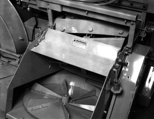
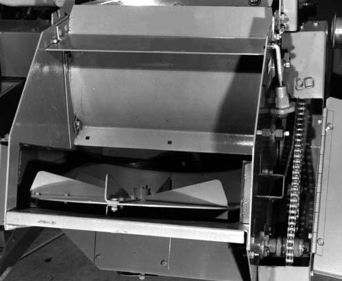
Fan Paddles (Fig. 28)
Over long periods of Harvester use, the tips of the six Blower Fan Paddles will wear and therefore require readjustment. The position of the Fan Paddles should be checked (and, if necessary, readjusted) after every 100 hours of operation.
Each Paddle Tip should be approximately 1/32 to 1/16 (0.8 to 1.5 mm) away from the Blower Rim Sheet at the 6 o’clock (bottom) position. An excellent method for checking the setting is to place a nickel and a dime side by side on the Rim Sheet. When the Paddle is rotated across the coins, it should pick up the nickel and leave the dime. To adjust the Paddles, proceed as follows:
1.Make sure the Rim Sheet is clean (free of grass, gum, or dirt). Clean the Rim Sheet by running wet forage through the Harvester or by scraping it, if you do NOT have an accessory Water Tank.
Caution
BE SURE to exercise the MANDATORY SAFETY SHUTDOWN PROCEDURE (page 8) BEFORE proceeding.
2.Check the Rim Sheet for dents and holes; replace if necessary.
3.Check to see if the Blower Paddle Arms are bent; replace or straighten, as required.
4.Loosen the four 1/2 Hexagon Nuts on each Paddle only enough so that the Paddles can be tapped toward the Rim Sheet. Access to the Nuts can be gained through the Spinner Chute opening in the rear Sidesheet. Align the Paddles over their full 4-3/4 (121 mm) width so that the Tips are 1/32 to 1/16 (0.8 to 1.5 mm) away from the Rim Sheet.
NOTE: If after several adjustments of the Paddles, they cannot be moved any closer to the Rim Sheet, replace them according to the procedure outlined under the Blower Fan Paddle topic in the Service Chapter of this manual.
5.Check the screws and nuts which secure the Paddle Arm to the Blower Disc to see that they are properly secured.
6.After all Paddles are adjusted and the attaching hardware is tightly secured, rotate the Fan again (by hand) to insure that it turns freely; if NOT, check and remove the obstruction.
7.Replace the Blower Covers, Chute and, close all Guards. Run the Harvester at idle speed and listen for noise from the Blower.
Increase the tractor RPM to full throttle and again listen for noise from the Blower. If any noise problem is heard, exercise the MANDATORY SAFETY SHUTDOWN PROCEDURE (page 8) and then proceed to identify and correct the problem.
CUTTERBAR (Figs. 29, 30 & 31)
NOTE: The two routine maintenance procedures which have the most significant effect on the quality of cut and fuel efficiency are Knife sharpening and Cutterbar adjustment. Frequent sharpening of the Knife edge accompanied by the proper Cutterbar adjustment, will significantly increase the life of the Knives and the Cutterbar as well as reduce the amount of fuel required to chop the forage. In most cases, daily sharpening of the Knives and proper adjustment of the Cutterbar to the Knives will be sufficient. However, in areas where the soil is abrasive, more frequent Knife sharpening and Cutterbar adjustment may be necessary.
After sharpening the Cylinder Knives, the Cutterbar requires a slight amount of adjustment toward the Knives. All Cutterbar adjustments are performed on the right side of the Harvester with all Covers and Shields kept in place. With the Harvester Cylinder operating at tractor engine idle speed and the Shifter Transmission deactivated by turning the Keyswitch OFF and removing the Key, proceed to adjust the Cutterbar as follows:

NOTE: It is NOT necessary to loosen the Cutter bar Hold-down Bolt on the right end of the Cutterbar while adjustments are being made. Also, the Spring-Torqued Hold-down Pin on the left side should NEVER be loosened, even when removing the Cutterbar.
4.Again, bring the right side of the Cutterbar to tick and then, back it off enough to stop the ticking.
The Cutterbar is now setup all the way across and backlash toward the Knives has been removed.
NOTE: When the cutting edge of the reversible Cutterbar NO longer stays sharp, the Cutterbar can be removed and changed (end-for-end) to place a new sharp edge toward the Knives. When one or both edges of the Cutterbar are NO longer sharp, one or the other can be renewed with the Knife Sharpener; refer to the Service chapter for details. After both edges are worn-down and can NO longer be renewed, the Cutterbar MUST be removed and replaced with a new Cutterbar.
Setting the Cutterbar requires listening for the Knives to tick the Cutterbar but, it is possible for the Knives to hit the right side of the Cutterbar when you are adjusting the left side and vice-versa, thus giving a wrong indication of the closeness of a Knife to the Cutterbar.
If you follow the method given here, the Knife will always tick the Cutterbar on the side that is being adjusted.
1.Move the left side of the Cutterbar away from the Cutting Cylinder two full turns of the Left Remote Adjusting Shaft.

2.Move the right side of the Cutterbar towards the Cutting Cylinder until a ticking sound is heard. Back the right side away from the Cylinder until the ticking stops and then 1/6 (one flat of the Nut) turn of the Nut further.
3.Adjust the left side of the Cutterbar towards the Cutting Cylinder until a ticking is heard and then, back the left side away from the Cylinder only enough to stop the ticking sound.
1 – 076964 Hardened Washer
2 – Frame
3 – 076965 Spring Washers (4)
4 – 076963 Nut
5 – 076962 Adjusting Nut
6 – 1/2 x 5 Cap Screw
7 – 076967 Rounded Key (1 of 2)
8 – 076966 Retaining Ring
9 – 0.05 to 0.08 (1.3 to 2 mm)*
10 – Cutterbar
11 – 076968 Stud
12 – 1/2 Lock Nut
* NOTE: As required, add or remove 076964 Hardened Washer(s) to obtain dimension.
Fig. 30: Cutterbar Right Side Adjustment Component Replacement Detail
SPOUT (Fig. 32)
The Harvester Spout is equipped with Electric Controls. Horizontal Extensions and/or Vertical Extensions are available to respectively lengthen and/or raise the point of discharge from the Cap end of the Spout. Approximate length and height variations for the Spout with or without different accessory Extensions are shown.

Warning
Properly support the Spout whenever it becomes necessary to remove the attaching hardware between it and the Blower Outlet or a Vertical Extension. The Spout, Outlet and Extensions have matching flanges which are bolted together; when the hardware is removed, the components will separate.
A - Spout
B - Vertical Extension
C - Horizontal Extension
D - Wagon Hitch Pin to End of Cap
E - Height from Ground
F -Tongue Pin Hole to Wagon Hitch Pin Hole [ 181-1/12 (4610 mm)]
All Dimensions are in Inches (Millimeters) Unless Otherwise Noted
NOTE: Actual Measurements vary on the basis of Tire size and adjusted Wheel Spindle positions.
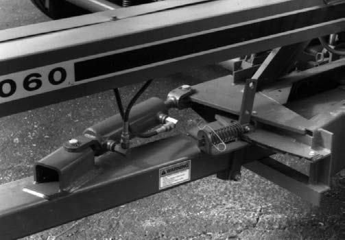
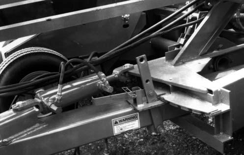
TONGUE (Figs. 33 & 34)
NOTE: When the Harvester is transported on the highway, the Lock Mechanism MUST be locked into the “Transport” position.
The Tongue of the Harvester can be manually repositioned in any one of four operating positions or into the “Transport” position, as desired. Select the appropriate position for operation with the least amount of offset in order to extend the Universal Joint life and to reduce vibration.
To reposition the Tongue, first remove and store the Lock Pin in the Latch Lever. Then, from the tractor seat, pull the Latch Release Cord and drive forward or back, as required to move the Tongue to a different notch position in the Frame. After the desired position is reached, release the Cord to allow the Lever to slip into and engage a notch in the Frame.
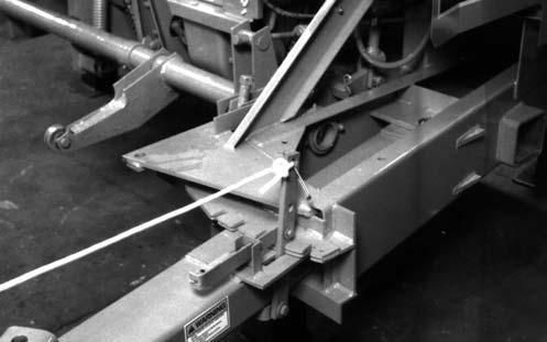
When this Kit is installed and ready for field operation, the Transport Lock Mechanism should be locked in the de-activated position, as shown in Fig. 34. When transporting the Harvester, the Latch Mechanism MUST be locked in the “Transport” position.
Drive Chains
The various Drive Chains of the Harvester are provided with appropriate adjustable-position or self-tensioning mechanisms.

Length of Cut Drive Chain (Fig. 35)
Unlock the Chain Adjustment Knob on the Length-ofCut Frame and adjust the Chain tension with the Knob for a slack of 1/4 to 3/8 (6 to 9.5 mm) in the strand of Chain between the Upper Feed Roll Drive Sprocket and the Length-of-Cut Drive Sprocket. After proper Chain tension is adjusted, BE SURE to lock the Knob.
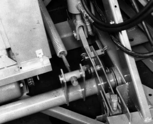
Attachment Driver (Fig. 36)
NOTE: For added convenience, a hydraulicallyoperated Tongue Kit is available for field installation to automatically reposition the Tongue from the tractor seat. Refer to the Optional Features & Accessories chapter for ordering information.
The Tongue can be remotely repositioned by obtaining and installing a Hydraulically-operated Tongue Kit.
The Attachment Driver Chain has an Idler Sprocket on the slack side of the Chain. Tension on the Chain should be checked after every 10 hours of operation and readjusted (if necessary) for a slack of 1/4 to 3/8 (6 to 9.5 mm) in the strand of Chain between the Attachment Drive Shaft Sprocket and the Lower Drive Sprocket.
NOTE: When re-tightening the Idler Sprocket mounting bolt, make sure the Idler Sprocket linesup with the Chain. Also, too much Chain tension can result in excessive Chain and Sprocket wear; avoid applying too much tension.
Lower Feed Rolls (Fig. 37)
The Lower Feed Roll Drive Chain tension is adjusted with a Chain Slide Mechanism. Chain deflection should be checked after every 50 hours of operation and readjusted (if necessary) for a 5/16 (8 mm) deflection on the strand of Chain opposite the Slide.

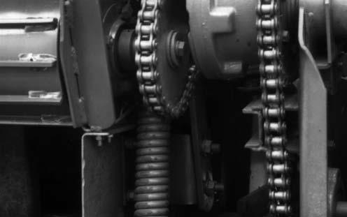

Shifter Transmission & Spinner Drives (Fig. 38 & see Fig. 35)
The Shifter Transmission Drive Chain and the Spinner Drive Chain each have self-adjusting Idlers which require NO further readjustment.
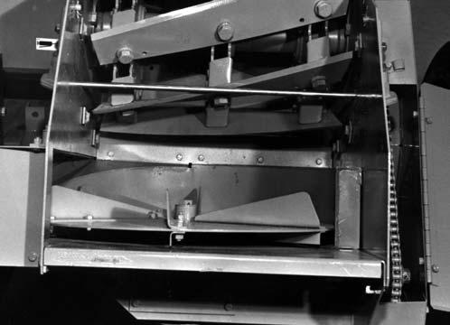
Upper Feed Rolls (Fig. 39)
The Upper Feed Roll Drive Chain has self-adjusting Roller Slides to maintain proper operating Chain tension; NO further adjustment is required. If, after a time, Slide wear is detected, the attaching hardware can be temporarily loosened and the Slide rotated to a new position.
FEED ROLL SPRINGS (See Fig. 37)
Tension Springs are provided on both sides of the Feed Roll Housing to apply pressure on the Feed Rolls while material is traveling between them. The Feed Roll Springs are factory adjusted so that all looseness (play) is eliminated. Tension needs only to be checked and adjusted if they are loose or after service has been performed which requires removing the Feed Roll Springs and Rolls.
Tension on each Spring can be readjusted by tightening each Spring Tensioning Bolt until there is no looseness and then one additional revolution of the Bolt. Then, tighten the Nut against the Nut casting. Do NOT tighten the Nut against the Frame Flange because the Bolt must be free to tilt with the Spring.
Front Pto Bearing Housing
The Front PTO Bearing Housing MUST be adjusted vertically in order to position the Drive Shaft and Telescoping Drive in a straight line. This adjustment is extremely important to minimize vibration. Refer to the Preparing for Field Operation chapter for details.
KNIVES (Fig. 40)
The Cutting Cylinder Knives will have to be readjusted whenever 1/4 (6 mm) or more is ground-off through repeated sharpening because the Cutterbar has only 1/4 (6 mm) of actual adjustment.
To adjust the Knives, proceed as follows:
Caution
BE SURE to exercise the MANDATORY SAFETY SHUTDOWN PROCEDURE (page 8) BEFORE attempting to adjust the Knives.
1.Remove and retain the Spinner and Cylinder Covers and the Recutter Screen (if present).
2.After cleaning-out the space between the Cutterbar and the Scraper, move the Cutterbar forward to the end of its travel.
3.Install the Knife Set-up Rod (which is stored in the Toolbox) through the access holes in the Cylinder Sidesheets.
4.Loosen the (3) Knife Bolts just enough to permit the Knife to be tapped into position.
5.Adjust the Knife to just clear or just touch the Setup Bar along the entire length of the Knife.
6.Tighten all (3) Knife Bolts to 220/240 ft-lb of torque and then recheck the clearance.
7.Repeat steps 4, 5 & 6 for all of the Knives. After all the Knives have been sharpened and adjusted to obtain a round Cylinder, readjust the Cutterbar following details in this chapter. Refer to the Service chapter for directives on sharpening the Knives. BE SURE to remove the Knife Set-up Rod and store it in the Toolbox. Then, reinstall the Spinner and Cylinder Covers and the Screen (if used) before resuming harvesting.
LENGTH OF CUT (See Fig. 35)
The Harvester Length of cut is regulated by two factors: the number of Cylinder Knives and the Length-of-Cut Sprocket which is mounted on the Shifter Transmission Output Shaft.
Refer to the Length of Cut chart provided for Sprocket and Knife combinations. Refer to the Service chapter for Knife removal and replacement details.
To change the Length of Cut Sprocket, proceed as follows:
* Optional (order separately)
1.Unlock the Chain Adjustment Knob on the Length of Cut Frame and completely release Chain tension.
2.Install the desired Length of Cut Sprocket using the existing Washers to align the new Sprocket.
3.After the desired Length of Cut Sprocket is installed, readjust the slack on the Length of Cut Drive Chain. To properly adjust the slack, rotate the Knob by hand until Chain is tight. Then, rotate the Knob counterclockwise 1/4 turn, to provide the correct slack. After the Chain slack is adjusted, BE SURE to reset the Knob Lock.
To reduce the amount of long pieces of hay or to crack kernels of corn, optional Recutter Screens can be ordered and installed; refer to the Screen Adjustment topics in this chapter, for further details. A Screen recommendation table is also provided to aid in proper Screen selection.
NOTE: To minimize the increased horsepower requirements, BE SURE to use the Sprocket which gives the longest acceptable Length of Cut in conjunction with the Screen. It should also be understood that the use of a Recutter Screen increases horsepower requirements and reduces harvesting capacity.
NOTE: To reduce the shelled corn loss from the Lower Feed Rolls, use a shorter Length of Cut Sprocket.
Drive) MUST be maintained with a 0.036 to 0.060″ (0.9 to 1.5 mm) gap between the Sensor Contact Point and the adjacent Sprocket. A lesser gap causes the Contact Point to make contact with the Sprocket due to Sprocket wobble or under lighter loads. A greater gap causes the Torque Sensing device to ratchet without releasing the Electric Clutch.
NOTE: The Torque Sensing device has a relatively short ratchet life.
TORQUE SENSOR CONTACT POINTS (Fig. 41)
NOTE: The following information applies ONLY to Harvesters which are equipped with Torque Sensors for overload protection.
To operate with maximum capacity sensing capability, the Torque Sensor Contact Points for each Sensor (one on the Feed Roll Drive and one on the Attachment
METAL STOP SOLENOID & STOP PAWL (Fig. 42)
NOTE: The following information applies ONLY to Harvesters which are equipped with Metal Detectors.
When the Solenoid is retracted (Normal Operating Position), the Stop Pawl is to be held 1/8″ (3 mm) away from the highest point on the Ratchet Wheel as shown. To adjust this distance, first loosen the (3) Bolts in the Solenoid Mount and slide the Mount towards or away from the Ratchet Wheel. After the 1/8″ (3 mm) clearance is obtained, tightly secure the (3) Bolts.
The (3) Rings, between the Solenoid and the Stop Pawl, MUST NOT be twisted. The Ring in the Solenoid Eyebolt and the one in the Stop Pawl are to be horizontal (positioned sideways). The center Ring is to be vertical (perpendicular to the other two). Rotate the Eyebolt, inside the Solenoid Boot to untwist the Rings.
After the preceding adjustments are made, recheck the Solenoid operation to insure that the Stop Pawl moves freely.
REAR CYLINDER TIE (See Fig. 38)
The Rear Cylinder Tie is provided as a stabilizer to maintain the position of the Cylinder Sidesheets. When desired or otherwise as necessary, the Tie can be removed for additional clearance to install a Recutter Screen or to adjust the Cylinder Knives.
Caution
The Cylinder Tie MUST ALWAYS be in place BEFORE operating the Harvester.
The Cylinder Tie is attached with the same hardware which secure the Cylinder Cover Mounting Brackets. After the Tie and Cover Mounting Brackets are loosely attached, align the Cover Mounting Brackets following details provided under the Cutting Cylinder topic in the Service chapter.
SCRAPER (See Fig. 31) CAUTION
BE SURE to exercise the MANDATORY SAFETY SHUTDOWN PROCEDURE (page 8) BEFORE attempting to adjust the Scraper.
NOTE: The Scraper MUST ALWAYS be set within 0.010 (0.25 mm) from the Smooth Feed Roll in order to prevent excessive wear on the Length of Cut Sprocket and to help prevent excessive horsepower consumption.
The Scraper, for the Rear Lower Smooth Feed Roll, can be adjusted or removed (if necessary) from outside the Harvester. The Scraper should be maintained in contact with the entire width of the Feed Roll. If readjustment is required, loosen the 1/2 Hexagon Nuts on each end of the Scraper and tap the Scraper ends down. If material is caught between the Scraper Tip and the Feed Roll, remove the Scraper by loosening the Nuts to permit the mounting bolts to drop-down in the slots in the Scraper and Cutterbar Support.
NOTE: Raise the Stem Deflectors, above each end of the Scraper, 1/4 (6 mm) to provide clearance for removing the Scraper.
Pull the Scraper out the right side and clean it. If the Scraper is badly worn or bent, replace it. Reinstall the Scraper by reversing the above procedure. Raise the 1/2 Bolts and Nuts, at each end of the Scraper, in the slots and tighten the Nuts so they are snug. Then, tap the ends of the Scraper down and secure it by tightening the Nuts.
NOTE: When the Scraper is reset, BE SURE to set the Stem Deflectors down against the Cutterbar and 1/32 (0.8 mm) forward of the cutting edge of the Cutterbar on its lower end. Carefully rotate the Cutting Cylinder (by hand) to make sure the Knives do NOT strike the top of the Stem Deflectors. MAKE SURE that the Stem Guide Bolts are tight. Loose Bolts will allow the crop to push the Guides into the Knives and severely damage the Cutting Cylinder.
Periodically check the area between the Scraper and Smooth Feed Roll to make sure that it is clean. This area can be cleaned from the outside of the Harvester by pushing a rod through the hole in the Sidesheet, between the Scraper and Feed Roll. It is build-up in this area that causes higher Torques which wear the Sprockets and increase horsepower consumption.
SQUARE HOLE SCREENS (Fig. 43)
Square Hole Screens are available in hole sizes from 3/4 to 4 (19 to 100 mm). Refer to the Setup & Assembly chapter for installation details.
6.Replace the Cylinder and Spinner Covers and tightly secure them.
7.Reinstall the Telescoping Drive and start the Harvester. Some ticking will probably occur; this is permissible and even desirable since operating the Harvester will eventually eliminate it.
NOTE: Slightly ticking Knives are acceptable (and even desirable) but, if the Harvester can NOT be easily started or if the Knives are making loud noises, the Screen MUST be readjusted.
High spots on a Screen can be beaten-down with a heavy bar, if they are NOT too close to the Screen Flanges. The Screen can only be moved about 1/4 (6 mm) inward from its initial position, with the Knives set out to a 9 (228 mm) radius. If the Screen can NOT be moved into the Knives far enough, the Knives will have to be reset and sharpened.
NOTE: Screens are also reversible so that, when the edges of the Screen holes become rounded, the Screen can be removed, rotated and replaced with the sharp edges facing the Knives.
STEM DEFLECTORS (See Fig. 31)
After the Screen is installed or after the Knives are sharpened, the Screen MUST be properly adjusted so that harvesting capacity is NOT decreased or so that power is NOT wasted due to hairpinning of the crop at the edges of the holes.
To adjust the mounted Screen, proceed as follows:
1.Remove the Spinner Cover and Cylinder Cover.
2.Loosen the Cam Bolts just enough so that the Cam Nuts can be rotated.
3.Turn the Spinner Disc (by hand) and, starting with the forward, then the middle and then, the rear Cams, turn each Cam Nut counterclockwise on the right side and clockwise on the left side until the Screen stops the Cutting Cylinder. Then, backoff the Nuts slightly. Repeat this process for all of the Cam Nuts.
4.After all of the Cam Nuts are adjusted, repeat the adjustment because the last adjusted Cams will affect the position of the Screen with respect to the first adjusted Cams. Adjust the Screen as close as possible to the Knives; a slight ticking is permissible.
5.Retighten the Cam Bolts.
Right and Left Stem Deflectors are located above the Cutterbar at each end. These Deflectors prevent forage stems from moving around the ends of the Knives. The bottom Deflector edges should be set down against the Cutterbar and the curved rear edges should be positioned about 1/32 to 1/16 (0.8 to 1.6 mm) from the Knives.

To adjust the Deflectors, loosen the two 3/8 Hexagon Head Cap Screws which are threaded into the Deflectors. Move the Deflector by tapping the 3/8 Screws. When the Deflectors are properly positioned, retighten the two Screws.
NOTE: MAKE SURE that the Stem Guide Bolts are tight. Loose Bolts will allow the crop to push the Guides into the Knives and severely damage the Cutting Cylinder.
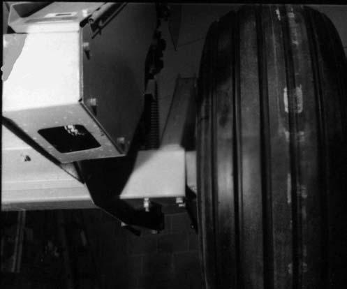
TIRES, WHEELS & AXLES (Figs. 44 & 45)
The Harvester can be obtained with either Standard Single Wheel, Flotation Tire or Tandem Axles.
All Axle options fit into the Harvester Frame in the same manner. Once the Axle Extensions are installed, the Axle Spacers (“L”-shaped Brackets) can be secured and remain in place.
Standard Single Wheel Axles,
44 & see Figs. 46 & 47)
The Axle Extensions can be placed into and secured to the Harvester Frame in any one of several positions to align the Wheels and Tires between crop rows. The various positions for the Axle Extensions are illustrated. A single 1/2 x 6 Bolt, Lock Washer and Hexagon Nut are used to secure the Extension to the Frame.
The Single Wheel Spindles can also be raised or lowered to adjust the height of the Harvester Frame to match the requirements of the Attachment and field conditions. Each Spindle is secured to the Axle Extension with (4 each) 1/2 x 1-1/2 Cap Screws, Lock Washers and Nuts.

Warning
BE SURE to properly position the jack under the Frame Axle and make sure that the jack base is firmly supported so that the jack does NOT slip-off the Frame Axles.
The various positions for the Spindles are illustrated. BE SURE to set both Spindles to the same height. To move the Wheels and Tires in or out or to adjust the Spindle heights, block the Harvester and jack the Frame up. Remove the attaching hardware, readjust the Axle Extensions or Spindles and resecure the attaching hardware.
Flotation Tire Axles, Wheels & Spindles (Figs. 44 & see Figs. 46 & 47)
The Axle Extensions can be placed into and secured to the Harvester Frame in any one of several positions to align the Wheels and Tires between crop rows. The various positions for the Axle Extensions are illustrated. A single 1/2 x 6 Bolt, Lock Washer and Hexagon Nut are used to secure the Extension to the Frame.
The Flotation Wheel Spindles can also be raised or lowered to adjust the height of the Harvester Frame to match the requirements of the Attachment and field conditions. The various positions for the Spindles are illustrated. Each Spindle is secured to the Axle Extension with (4 each) Cap Screws, Plain Washers, Lock Washers and Nuts.
Warning
BE SURE to properly position the jack under the Frame Axle and make sure that the jack base is firmly supported so that the jack does NOT slip-off the Frame Axles.
To move the Wheels and Tires in or out or to adjust the Spindle heights, block the Harvester and jack the Frame up. Remove the attaching hardware, adjust the Axle Extensions in or out and then resecure the attaching hardware. To change the Spindle height, temporarily loosen (but do not remove) the 4 Capscrews in each
Spindle. Then, Slide the Spindle up or down and resecure the Spindle attaching hardware. BE SURE to set both Spindles to the same height.
Tandem Wheel Axles, Spindles, Wheels & Tires (Fig. 45, 46 & see Fig. 48)
The Tandem Axle Extensions can be placed into and secured to the Harvester Frame in any one of several positions to align the Wheels and Tires between the crop rows. The various positions of the Axle Extensions are illustrated. A single 1/2 x 6 Bolt, Lock Washer and Nut are used to secure each Extension to the Harvester Frame.
The Tandem Wheel Spindles can also be raised or lowered to adjust the height of the Harvester Frame to match the requirements of the Attachment and field conditions. The Spindles are secured with a total of (6 each) 1/2 x 1-1/2 Cap Screws, Lock Washers and Plain Washers. The various positions for the Spindles are illustrated. BE SURE to adjust all four Spindles to the same height.
NOTE: The topmost Spindle Mounting Bolts require only to be temporarily loosened when the Spindle positions are readjusted.
To move the Wheels and Tires in or out or to adjust the Spindle positions, block the Harvester and jack the Frame up. Remove the attaching hardware, readjust the Axle Extensions or Spindles and resecure the hardware.
Warning
BE SURE to properly position the jack under the Frame Axle and make sure that the jack base is firmly supported so that the jack does NOT slip-off the Frame Axles.
NOTE: The following information applies only to operating a Harvester equipped with Tandem Axles in fields rutted by the wheels of center pivot irrigators.
Two metal doughnut-shaped Spacers (076279) are provided with the Tandem Axle assemblies. These Spacers can be assembled onto the short shafts which protrude between the fork of each Axle Extension and secured with the Cotter Pins provided. When installed, the Spacers greatly limit the Wheel Beam oscillation. They are recommended for use where center pivot irrigation systems are employed. Do NOT use the Spacers in any other conditions.
NOTE: The following information applies only to equipping Tandem Axles with other than the Tires furnished with each factory provided assembly.
A Tire, with larger than a 27 outside diameter, can NOT be used on the right front Wheel if the Harvester is going to be operated with an HA1100 or HA1110 Hay Attachment. A larger Tire will interfere with the HA1100 or HA1110 Attachment Flotation Wheel and the right sidesheet of the Attachment will cut the Tire while passing-over an object which raises the right front Tandem Wheel as the Attachment drops below the normal ground position.
WAGON HITCHPLATE (Fig. 49)
Two Wagon Hitchplates are provided on the Harvester. One of the Plates is attached in the “Transport” position and is designed to locate the trailing forage box as far to the right as possible for viewing traffic behind the box while traveling on a public highway. The other Hitchplate can be mounted in any one of many positions to align the forage box tires between the crop rows, as required. A “mud’’ position is also provided, on the far left end of the Frame, for use in helping to reduce Harvester side draft when operating in muddy or soft fields. Suggested Wagon Hitchplate positions, relative to the various Attachments, are identified in the illustrations provided.
A - Tandem Axle Wheel
B - Single Axle Wheel
C - Wagon Hitch Plate
D - 48 (1211) Min. to 72 (1821) Max.
E - 78 (1981) Min. to 98 (2489) Max. w/Standard Tires
80-1/2 (2045) Min. to 98 (2489) Max. w/Flotation Tires
F - 83 (2118) Min. to 98 (2494) Max.
G - Centerline of Cutting Cylinder w/Standard Tires w/Flotation Tires
H - 27-13/16 (706) Min. to 51 (1295) Max.
30-5/16(770) Min. to 51 (1295) Max.
J - Transport Hitch Plate
K - 50 to 100 (1270 to 2540)
L - 33 (838) Min. to 51 (1300) Max.
M - Tongue
N - 20 (508)
All Dimensions are in Inches (Millimeters) Unless Otherwise Noted
A - Standard Axle Extension (Top Surface)
B - Axle Extension
C - Spindle Plate
D - Wheel
E - High Harvester Spindle Position
F - Low Harvester Spindle Position
NOTE: Flotation Axle NOT Shown
* S = Standard Axle, F = Flotation Axle
A -Right Front Wheel
B -Axle Extension
C -Spindle Plate (Typical)
D -Beam (Top Surface)
E -Right Rear Wheel
F -Spindle Plate Assembly in “High” Harvester Position
G -Spindle Plate Assembly in “Low” Harvester Position
H -Spindle Bolt (1 of 6)