9 minute read
GEHL AGRICULTURE NEW AGRICULTURAL EQUIPMENT WARRANTY

GEHL AGRICULTURE DIVISION of the GEHL COMPANY, hereinafter referred to as Gehl, warrants new Gehl agricultural equipment, skid loaders, Gehlmax articulated loaders and attachments, to the Original Retail Purchaser to be free from defects in material and workmanship for a period of twelve (12) months from the Warranty Start Date, except as set forth below:
The following parts are warranted for a period of ten (10) years from the Warranty Start Date for replacement only, labor and freight excluded, unless defect occurs during initial twelve (12) month warranty period:
MANURE SPREADER sides on box spreaders or tank on Scavenger spreaders against perforation (rust through) and Clad-Tuff floor against delamination.
BU970 SELF-UNLOADING FORAGE BOX metal sides, end panels and roof against perforation (rust through) and platform against delamination.
GEHL AGRICULTURE WARRANTY SERVICE INCLUDES:
Genuine Gehl parts and labor costs required to repair or replace equipment at the selling dealer’s business location.
STATEMENT.
GEHL WARRANTY SERVICE DOES NOT INCLUDE:
1.Transportation to selling dealer’s business location or, at the option of the Original Retail Purchaser, the cost of a service call.
2.Used equipment.
3.Components covered by their own non-Gehl warranties, such as tires, trade accessories and engines.
4.Normal maintenance service and expendable, high wear items.
5.Repairs or adjustments caused by: improper use; failure to follow recommended maintenance procedures; use of unauthorized attachments; accident or other casualty.
6.Liability for incidental or consequential damages of any type, including, but not limited to lost profits or expenses of acquiring replacement equipment.
No agent, employee or representative of Gehl has any authority to bind Gehl to any warranty except as specifically set forth herein. Any of these limitations excluded by local law shall be deemed deleted from this warranty; all other terms will continue to apply.
CHAPTER
CHAPTER 3
CHAPTER
CHAPTER 5
CHAPTER 6
CHAPTER 7
CHAPTER 8
CHAPTER 9
CHAPTER 10
CHAPTER 11
Field Operation80
CHAPTER 12 Storage85
CHAPTER 13 Troubleshooting86
CHAPTER 14 Set-up & Assembly102
CHAPTER 15 Optional Features & Accessories121
CHAPTER 16 Decal Locations124
CHAPTER 17 Maintenance Log128
Chapter 1 Introduction
Thank you for purchasing this piece of Gehl equipment. We are sure that your decision was strongly considered and that you are looking forward to many years of work from this machine.
We, as a Company, have invested a great deal of time and effort in developing our lines of equipment. The equipment you have purchased is built with a great deal of pride and designed to give you long life, efficient operation, durability and dependability.
This manual was developed specifically for the machine you have purchased. The information within is for your assistance in preparing, adjusting, maintaining and servicing your machine. More importantly, this manual provides an operating plan for safe and proper use of your machine. Major points of safe operation are detailed in the SAFETY chapter of this manual. Refer to the Table of Contents for an outline (by chapters) of this manual. Use the Index, located at the back of this manual, for specific references. A chart depicting standard hardware torques is located on the inside back cover.
A Manual Pocket is provided on the inside of the Toolbox Cover for storing the Operator’s Manual. After using the Manual, please return it to the Pocket and keep it with the unit at all times! Furthermore, if this machine is resold, Gehl Company recommends that this Manual be given to the new owner.
Modern machinery has become more sophisticated and, with that in mind, Gehl Company asks that you read and understand the contents of this manual COMPLETELY and become familiar with your new machine, BEFORE attempting to operate it.
The Gehl dealer organization stands ready to provide you with any assistance you may require and carries genuine Gehl service parts. All parts should be obtained from or ordered through your Gehl Dealer. Give complete information about the part and include the model and serial numbers of your Harvester.
Numbers for this unit are stamped on a plate located on the right side of the Main Frame adjacent to the Cylinder Shaft Bearing.
‘‘Right’’ and ‘‘left’’ are determined from a position standing behind the unit and facing forward. From this position, the Telescoping Drive is on the ‘‘left’’ and the Feed Roll Housing and Cutting Cylinder are on the ‘‘right’’.
Throughout this manual, information is provided which is set in italic type and introduced by the word NOTE BE SURE to read carefully and comply with the message or directive given. Following this information will improve your operating or maintenance efficiency, help you to avoid costly breakdowns or unnecessary damage and extend your machine’s life.
Gehl Company reserves the right to make changes or improvements in the design or construction of any part without incurring the obligation to install such changes on any unit previously delivered.
The Gehl Company, in cooperation with the American Society of Agricultural Engineers and the Society of Automotive Engineers, has adopted this SAFETY ALERT SYMBOL to pinpoint characteristics which, if NOT properly followed, can create a safety hazard. When you see this symbol in this manual or on the machine itself, you are reminded to BE ALERT! Your personal safety is involved!
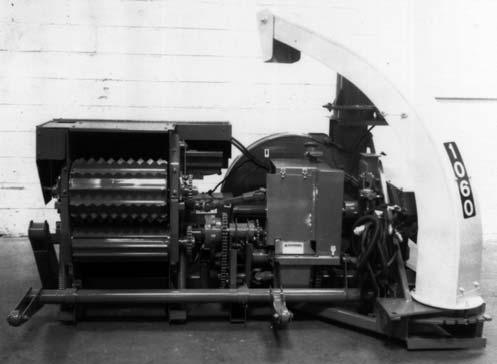
Chapter 2 Specifications
All Dimension are in Inches (Millimeters) Unless Otherwise Noted Model & Description CB1060/1065 Forage Harvester .
requirement Up to 200 PTO hp (149 kw) Tractor with 1–3/8 or 1–3/4 Diameter PTO Shaft operating at 1000 RPM
Feed Rolls & Attachment Engaged by an Electro–magnetic 12″ Diameter Clutch Driving a Solenoid–reversed Shifter Transmission with Sealed Roller Bearings Running in Oil
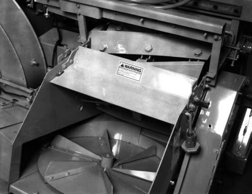
Lower Feed Rolls & Spinner Protected by Shear Bolts
Impact Pin-protected Main Drive
Bevel Gearbox with Tapered Bearings Running in Oil
Multi–position Wagon Hitchplate
Separate Fixed–position Wagon Transport Plate
Horizontally and Vertically Adjustable Wheel Mounts
Two Serrated, One Fluted and One Smooth Feed Roll
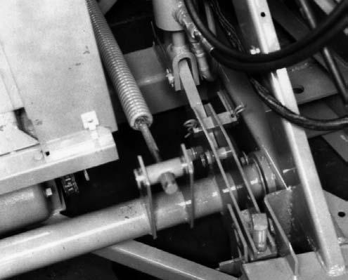
Hydraulically–controlled Attachment Lift System with Flotation Spring
Attachment Lift System has Adjustable Lift Height and Down-Stop
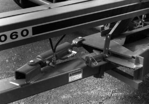
Adjustable Tongue Hitch with Four Operating and One Transport Position
Hydraulically–powered Knife & Cutterbar Sharpener
Overrunning Clutch on Main Drive
Replaceable Blower Wear Liner
Replaceable Spout Wear Liner
Electrically–controlled Spout with Full Range from Rear to Side Delivery
Electrically–controlled Spout Cap
1–3/8 or 1–3/4 1000 RPM Telescoping PTO Connection
Optional (Factory-installed ONLY) Features:
Shear Bolt Model - Shear Bolt Protection on Upper Feed Rolls
Torque Sensor Model - Automatic Disengagement of Feed Rolls and Attachment whenever the Feed Rolls are Overloaded, the Attachment is Overloaded, or the Blower Speed is Too Low
Tungsten Carbide–faced Knives
Tungsten Carbide–faced Reversible Cutterbar
Single Station Cutterbar Adjustment
Metal Detector Model - Automatic Disengagement of Feed Rolls and Attachment Whenever Ferrous Metal is Detected, the Feed Rolls are Overloaded, the Attachment is Overloaded, or the Blower Speed is Too Low
Optional Axle and Tire Selections:
Single Wheel Axle Set Options:
(2) 14 x 8.00 D.C. Wheels (less Tires) or(2) 14 x 8.00 D.C. Wheels with Mounted 11L x 14 6–Ply Rated Implement Tires or(2) 15 x 10.00 D.C. Wheels (less Tires) or(2) 15 x 10.00 D.C. Wheels with Mounted 12.5L x 15 8–Ply Rated Implement Tires
Flotation Axle Set:
(2) W11C x 16.1 Wheels with Mounted 16.5L x 16.1 8–Ply Rated Implement Tires
Tandem Axle Set:
(4) 15 x 8.00 D.C. Wheels with Mounted 27 x 9.50 x 15 6–Ply Rated Implement Tires
Accessories:
Hydraulically-controlled Tongue with Pin-latched Transport Position Requiring a Second Hydraulic Output on Tractor
Length–of–Cut Sprockets
Long Cut Kit
1–ft or 2–ft Vertical Spout Extensions
Kit for Relocating Cap Motor when Factory-installed
1–ft Vertical Spout Extension is Removed
3–1/2–ft or 5–1/2–ft Horizontal Spout Extension Kits
Spout Tripod Kit (for use with any Extensions)
Reversible Square–holed Screens in Sizes from 3/4″ through 4″
Wet Crop Deflector
Offset Wagon Hitch
Tunnel Switch Kit (for Water Tank Option on Shear Bolt Models)
Wiring Harness for a Second Tractor
Wiring Harness Extension
Safety Tow Chain
Chapter 3 Checklists
PRE-DELIVERY
After the Harvester has been completely set–up, the following inspections MUST be made before delivering it to the Customer. Check off each item after prescribed action is taken.
Check that:
Forage Harvester has been assembled correctly according to instructions in the Set–up & Assembly chapter of this manual.
All Grease Fittings have been properly lubricated, Chains oiled and the Transmission and Gearbox have been filled to the proper operating levels; see Lubrication chapter of this manual for specific details.
All Guards, Shields and Decals are in place and securely attached.
All fasteners are properly secured, including the Wheel Lug Nuts.
Tires are properly mounted and inflated to the appropriate pressure listed in the Service chapter.
All adjustments are made to comply with the settings given in the Adjustments chapter of this manual.
Serial Number for this unit is recorded in spaces provided on this page and page 2.
Hook the unit up to a 1000 RPM tractor and test–run the unit while making sure that proper operation is exhibited by all components.
Check that:
With engine off, the Rotating PTO Shield turns freely. All Drives, Chains and Belts are rotating smoothly and operating properly.
The Feed Roll Shifter Transmission, Spout and Cap Control Mechanisms are operating smoothly and properly. If Harvester is being delivered with a mounted and connected attachment, such as a Gehl Hay or Corn Head, make the following inspections.
Check that:
The Gehl Attachment has been properly attached to the Harvester; check for correct Drive fastener replacement.
The Drive Chain tension is properly adjusted.
Attachment has been properly lubricated according to reference in the separate Operator’s Manual for the Attachment.
Harvester Lift system is correctly adjusted for the Attachment.
Operator’s Manual for the Attachment is provided.
I acknowledge that pre-delivery procedures were performed on this unit at outlined above.
Dealership Name
Dealer Representative’s Name
Date Checklist Filled-out
Serial Number DELIVERY
The following Checklist is an important reminder of valuable information that MUST be passed on to the Customer at the time the unit is delivered. Check off each item as you explain it to the Customer.
Give Operator’s Manual, which is stored in a Compartment on the underside of the Toolbox Cover, to the Customer and instruct Customer and all operators to be sure to read and completely understand its contents BEFORE operating the unit.
Direct Customer on how to use the Index of this manual as a quick page number locating guide.
Explain and review with Customer the SAFETY chapter of this manual.
Explain and review with Customer the Controls & Safety Equipment chapter of this manual.
Explain that regular lubrication is required for continued proper operation and long life. Review with Customer the Lubrication chapter of this manual.
Explain and review the Service chapter of this manual. Remind customer about Rim Sheet Take-up Nut torque. Explain the Length–of–Cut topic in the Adjustments chapter.
Explain how to use the Knife Sharpener and the importance of sharp Knives and correct adjustment to Cutterbar. Explain the importance of correct tractor hook–up and Drive Line alignment.
Review with him the Preparing for Field Operation chapter.
Customer’s Signature
Date Delivered (Dealer’s File Copy)
Intentionally Blank
(To be removed as Dealer’s file copy)
Chapter 3 Checklists
PRE-DELIVERY
After the Harvester has been completely set–up, the following inspections MUST be made before delivering it to the Customer. Check off each item after prescribed action is taken.
Check that:
Forage Harvester has been assembled correctly according to instructions in the Set–up & Assembly chapter of this manual.
All Grease Fittings have been properly lubricated, Chains oiled and the Transmission and Gearbox have been filled to the proper operating levels; see Lubrication chapter of this manual for specific details.
All Guards, Shields and Decals are in place and securely attached.
All fasteners are properly secured, including the Wheel Lug Nuts.
Tires are properly mounted and inflated to the appropriate pressure listed in the Service chapter.
All adjustments are made to comply with the settings given in the Adjustments chapter of this manual.
Serial Number for this unit is recorded in spaces provided on this page and page 2.
Hook the unit up to a 1000 RPM tractor and test–run the unit while making sure that proper operation is exhibited by all components.
Check that:
With engine off, the Rotating PTO Shield turns freely. All Drives, Chains and Belts are rotating smoothly and operating properly.
The Feed Roll Shifter Transmission, Spout and Cap Control Mechanisms are operating smoothly and properly. If Harvester is being delivered with a mounted and connected attachment, such as a Gehl Hay or Corn Head, make the following inspections.
Check that:
The Gehl Attachment has been properly attached to the Harvester; check for correct Drive fastener replacement.
The Drive Chain tension is properly adjusted.
Attachment has been properly lubricated according to reference in the separate Operator’s Manual for the Attachment.
Harvester Lift system is correctly adjusted for the Attachment.
Operator’s Manual for the Attachment is provided.
I acknowledge that pre-delivery procedures were performed on this unit at outlined above.
Dealership Name
Dealer Representative’s Name
Date Checklist Filled-out
Serial Number
DELIVERY
The following Checklist is an important reminder of valuable information that MUST be passed on to the Customer at the time the unit is delivered. Check off each item as you explain it to the Customer.
Give Operator’s Manual, which is stored in a Compartment on the underside of the Toolbox Cover, to the Customer and instruct Customer and all operators to be sure to read and completely understand its contents BEFORE operating the unit.
Direct Customer on how to use the Index of this manual as a quick page number locating guide.
Explain and review with Customer the SAFETY chapter of this manual.
Explain and review with Customer the Controls & Safety Equipment chapter of this manual.
Explain that regular lubrication is required for continued proper operation and long life. Review with Customer the Lubrication chapter of this manual.
Explain and review the Service chapter of this manual. Remind customer about Rim Sheet Take-up Nut torque. Explain the Length–of–Cut topic in the Adjustments chapter.
Explain how to use the Knife Sharpener and the importance of sharp Knives and correct adjustment to Cutterbar.
Explain the importance of correct tractor hook–up and Drive Line alignment.
Review with him the Preparing for Field Operation chapter.
Customer’s Signature
Date Delivered (Pages 5 and 6 have been removed at perforation)