29 minute read
CHAPTER 14 SET-UP & ASSEMBLY


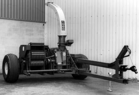
The Forage Harvester is shipped in the configuration shown in Fig. 92. The following common component completing parts are NOT attached to the Main unit:
Extension is being installed in the future (anytime after initial set-up), some assembled components will have to be removed and replaced.
NOTE: The following abbreviations are used in these procedures:
CB-Carriage Bolt
CS-Cap Screw (Hexagon Head)
RHMS-Round Head Machine Screw
SHSS-Socket Head Set Screw
THMS-Truss Head Machine Screw
N-Nut (Hexagon)
LN-Lock Nut (Hexagon)
HMN-Hexagon Machine Nut
WN-Wing Nut
Axles, Wheels & Tires
Tongue
Hitchjack
Front Bearing Stand, Main Drive and Guard
Telescoping PTO Drive
1-3/4 Drive Tongue Extension
Procedures established in this set-up instruction are given in a step-by-step manner, with various parts of the assembly process listed in such a way as to make it possible for one set-up person (with appropriate tools and equipment) to do the sequence without having to remove parts in order to make other component attachments. This chapter is divided into two topics: Common Components and Accessory Components. Accessory Components, such as a Tripod or Horizontal Extensions, are also referenced in the Spout and Controls mounting procedures so as to likewise help to avoid unnecessary removal and replacement steps during initial set-up. It should be understood that, if an additional Vertical Spout Extension or Horizontal Spout
L-Lock (Washer)
P-Plain (Washer)
NF-National Fine (Thread)
Unless otherwise noted, the standard fastening procedure is to secure two parts with a CS, L and N. A part with a mounting slot should be secured with a P against the slotted surface. Attaching hardware, which will require installation in the path of the cut crop, should always be installed with the head of the screw on the same side of the part which will be in contact with the material.
NOTE: Before proceeding, remove all components which are attached or banded to the Harvester Frame or otherwise included in the Toolbox. Shear Bolts should also be taken out of the Toolbox and placed in appropriate Shear Bolt Holders, where provided. As shown in Fig. 92, The Spout and Cap assembly is shipped attached to the Harvester Frame and MUST be removed before proceeding to setup the unit..
Common Components
Step 1: Tongue (Fig. 93)
Before the Tongue is attached to the Main Frame, grease the pivot surfaces. Then, slide the Tongue into the Main Frame and fasten it with the Pivot Pin and a 1/4 x 2 Cotter Pin (from Toolbox).
Step 2: Axles, Wheels and Tires (Figs. 94, 95 & 96)
Mounting procedures for the Single Axles, the Flotation Axles, or the Tandem Axle assemblies are essentially the same. If Single Wheel Axles are being installed and the Tires were purchased locally, BE SURE to have the appropriate Tires properly mounted on the Wheels before attempting to install the Axle Extensions into the Harvester Frame.

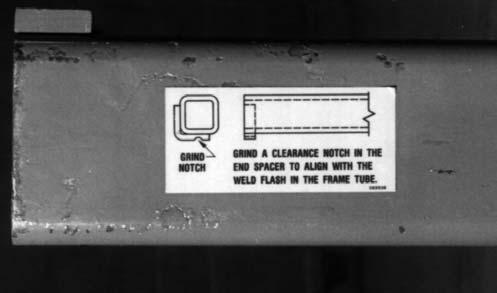
NOTE: Before the Axle Extensions can be installed, a notch to match the inside weld flash location may have to be ground into the End Spacer of both Axle Extensions. A Decal, displaying this information is provided on the Extension.
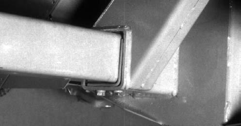
To install the Axle Extensions, carefully raise and properly block the Main Frame off the floor a sufficient amount to provide clearance to insert the Axles with mounted Wheels and Tires. BE SURE when the Tires are mounted that the Valve Stems face out. The Wheels should be installed and secured with 90 ft-lb (124.5 Nm) torque. The standard Single Wheel Axle Extensions have Gussets on the ends which MUST be installed facing down. The Flotation Axle Extensions have Gussets on the ends that MUST be installed facing up. The Tandem Axle Spindle assemblies have Gussets on their top sides which MUST be installed facing up. For Flotation and Tandem Axle assemblies, BE SURE to install assembly labeled ’’Left’’ on the left side of the Harvester. Before an Axle Extension can be inserted into the Harvester Frame Tube on either side, the Angled Axle Spacers MUST be temporarily removed and then replaced after the Extensions are inserted. After the Spacers are secured, the Extensions should be secured with (1 each) 1/2 x 6 CS, L and N.
NOTE: Refer to the Adjustments chapter for Spindle height and Wheel positioning details, if an Attachment is being mounted as part of this set-up and assembly procedure.
Step 3:
(Fig.
Step 4: Front Bearing Stand, Main Drive and Guards (Figs. 97 & 98)
NOTE: The following mounting procedure is best accomplished by two setup people.
First, layout the components along side the Tongue and align them with regard to their appropriate direction and position of attachment. Next, remove and retain the Top and Bottom Drive Joint Guards and their attaching hardware, and the two PTO Support Side Shields and their attaching hardware. Then, remove and retain the (2 each) 3/8 x 5-1/2 CS, P, L and N from the Front Bearing Bracket.
Next, raise the entire Main Drive assembly up and rest it on top of the Tongue, Then, raise the back end of the Drive and attach the Flange on the end to the Overrunning Clutch with the two Impact Pins (5/16 x 3-1/4 Grade 5 Bolts) and double Nuts. Then, raise the front end of the Drive and place the Front Bearing Stand over the Drive Line while aligning the (4) Stand mounting holes with the holes in the Tongue. Secure the Stand to the Tongue with (4 each) 1/2 x 5-1/2 CS, L and N. After the Stand is attached, raise the front end of the Drive and secure the Front Bearing Housing into the appropriate holes of the Stand with (2 each) 3/8 x 5-1/2 CS, P, L and N.
1/2 x 5-1/2
NOTE: Select the appropriate pair of holes for aligning the Bearing Housing according to details in the Preparing for Field Operation chapter.

Attach the Hitchjack to the mating Hub on the Tongue. Swing the Jack down and lock it in the ”Supporting” position with the Lockpin provided. Block the Wheels, in the front and back on both sides of the Harvester, and adjust the Jack to level the Tongue.
Properly position and fasten one Side Shield to each side of the Front Bearing Stand, using (2 each) 3/8 x 2 CB, P and LN, for each Shield. Place the CB through the top and bottom holes in the Shield and through the corresponding holes in the Front Bearing Stand. If the Front Bearing hardware occupies one of the sets of holes in the Bearing Stand, then fasten the Shield using the remaining two holes.

At the front end of the Main Drive, loosen (but do NOT remove) the (2 each side) 3/8 Bolts which are securing the front end of the main Drive Guard to the Bearing Support. Raise the rear of the Main Drive Guard and place it between the two PTO Shield Support Channels and secure the parts with (2 each side) 3/8 x 3/4 CS, L & N.
Before retightening the (4) 3/8 Bolts which secure the front end of the Tubular Drive Guard to the Bearing Support, position the Tongue and latch it in the center Notch in the Pivot Frame. Then, slide the Tubular Drive Guard ahead and back in order to find the center point of its travel. Once the center point is obtained, the (2 each side) 3/8 Bolts can be tightly secured to fix the position of the Guard.
Step 5a: Telescoping PTO Drive
(Figs. 99 & 100 & see Fig. 97)
Warning
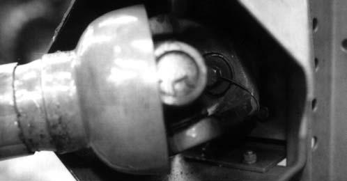
The Safety Lock Wire MUST be installed as a precaution to prevent the Special Screw from loosening and falling-out and thus enabling the Telescoping Drive to separate from the Drive Shaft while operating Harvester. NEVER attempt to mix the Front and Rear Halves of the 1-3/8 and 1-3/4 Telescoping PTO Drives.
NOTE: The Telescoping Drive Yoke and Main Drive Shaft Splines are manufactured to mate together in only one position.
Remove and retain the Safety Wire, Special Cap Screw and large Washer from the end of the Main Drive Shaft, which protrudes through the Front Bearing. Clean and lightly grease the Telescoping Drive Yoke and Drive Shaft Splines before proceeding to slide the Yoke onto the Shaft. Secure the Yoke to the Shaft by installing and securing the Special Cap Screw and large Washer. After tightening the Special Screw, thread the Safety Wire through the hole in the head of the Special Cap Screw and fasten the Wire around the Drive Yoke. After the Safety Wire is secured, install and secure the Top and Bottom Joint Guards which were removed in step 4.
Step
5b: 1-3/4 Drive Tongue
Extension (Fig. 100)
NOTE: The following information applies only to a Harvester which is going to be equipped with a 1-3/4 Telescoping PTO Drive.
Install the Tongue Extension in the following manner:
1.Remove and retain the Upper and Lower Hitch Clips and Spacer.
2.Refer to the illustration provided and properly position and secure the Tongue Extension as shown using the existing 5/8 x 6 CS, L and N.
3.Preassemble Upper Clip, Special Washer, existing Spacer, Special Washer and Lower Clip with a 5/8 x 5 CS, L and N. Next, secure this assembly to the Tongue Extension, with (2 each) 5/8 x 6-1/2 CS, L and N.
4.Tightly secure all mounting hardware.
Step 6a: Tongue Control Latch Rope (Fig. 101)
NOTE: The following information applies ONLY to a Harvester which is NOT going to be equipped with the optional Hydraulic Tongue Control Cylinder.
the Rope MUST be kept away from the Telescoping PTO Drive.
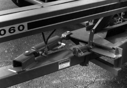
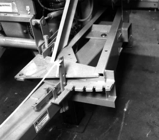
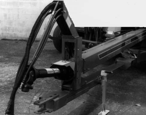
Step 6b: Tongue Control Cylinder & Hoses (Figs. 102, 103, 104
& 105)
NOTE: The following information applies ONLY to a Harvester which is going to be equipped with the optional Hydraulic Tongue Control Cylinder. In addition, when routing the hydraulic Hoses inside the Hose Side Cover, the Tongue should be swung-out to the maximum left (opposite of Transport) position to assure an ample amount of Hose will be available at the rear of the Drive Line.
To install the Tongue Controls, proceed as follows:
1.Properly position and secure the Notch Cover to the Harvester Frame with (1 each) 5/16 x 1 CS, L and N and, a 5/16 TFS as shown.
2.Properly position and secure the Cylinder to the Tongue and Harvester Frame with a Cylinder Pin and two 3/16 x 1-1/2 Cotter Pins on each end as shown.

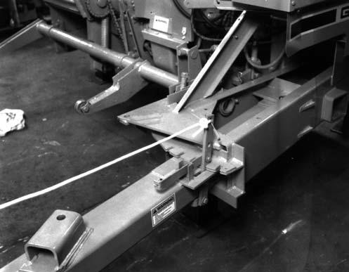
1 – Control Rope Fastened into top hole in Tongue
Fig. 101: Tongue Swung-out to Next to Widest Field-operating Position
The standard mechanical Tongue Latch is operated with a Control Rope. Attach and secure the Rope (taken from the Toolbox) to the top (chamfered) hole in the Tongue Latch. Route the Rope towards the tractor. The Rope needs enough slack for making turns with the tractor, but
NOTE: The Rod end of the Cylinder MUST be attached to the Harvester Frame. The Cylinder Ports MUST face the left side of the Harvester.

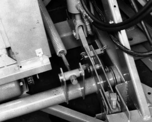
3.Using a drop of Loctite (or equivalent hydraulic sealing compound), install a 90° Swivel Adapter Union into each of the Cylinder ports; one of the Adapter Unions has a built-in Restrictor. When correctly installed, the 90° Fittings are to face upward and toward the opening in the bottom of the Hose Cover.
4.Remove the Top Cover from the Hose Side Cover. Then, properly position and secure the two Hose Guards into the hole in the bottom of the Hose Side Cover with (2 each) 1/4 x 1/2 CB, L and N.
5.Attach the Hoses to the Fittings on the Cylinder and route the Hoses from the Cylinder up through the Access Hole in the bottom of the Hose Cover, along the Main Drive Line Shield and up under the Hose Holder on top of the Front Bearing Stand. Anchor the Hoses to the Hose Holder with the Double Hose Clamp on the left side.
NOTE: Other Hoses and wiring will be added in later steps before reinstalling the Top Hose Cover.
6.Obtain and install appropriate disconnects to match your tractor’s hydraulic output terminations.
Step 7: Spout, Cap and Controls (Figs.
Caution
Because of the weight and awkwardness of the Spout (and Extensions), it is best that at least two people carry-out these Spout mounting procedures.
NOTE: If the Harvester is going to be set-up with mounted Vertical and/or Horizontal Extensions, refer to the Accessory Components topic, in this chapter, for mounting details. In addition, if the Spout MUST be installed without the standard 1-foot Vertical Extension provided, a special Spout Capmotor Relocation Kit MUST be obtained and installed per the information provided with the Kit. Begin this assembly by first installing the Cap Spring (from the Toolbox) between the hole in the Cap and the Bracket on the Spout (or Horizontal Extension).


Vertical Spout Extension. The bottom (rear side) of the Spout should be on the same side of the Extension as the Cap Control Motor. Install eight (8) 1/2 x 1-1/4 CS through the Spout and Extension. Secure each CS with a LN.
Remove the Spout and its shipping parts from the
Frame; discard the shipping parts.
Carefully raise and properly support the Spout in the ’’rear delivery’’ position on top of the standard 1-foot
NOTE: Check that the Spout is NOT binding before proceeding. If necessary, readjust the Clamps and Spacers. At this time also, adjust the Tripod Brace and Arm (where applicable), to find the proper alignment for the Spout (and Tripod) which best enables turning the Spout with the least amount of resistance.
Mount the Angle Bracket to the side of the Spout (or Horizontal Extension) using the hole provided. Secure the Angle with a 5/16 x 3/4 CS, L and N. Place the head of the CS inside the Spout.
Temporarily remove the rear 1/2 N, L and (1 of 2) P from the middle of the left side of the Spout. Then, install a Pulley onto the smaller end of an S-Hook and squeeze the S-Hook shut. Install the larger end of the S-Hook over the 1/2 CB and replace the P, L and N. The S-Hook should be between the two (2) P.
Form another S-Hook and Pulley assembly and install this onto the Cap. BE SURE to secure the S-Hook to the Cap and Pulley by squeezing the ends shut.
For a horizontally extended Spout application, temporarily remove the LN from the 5/16 x 1-1/2 THMS above the Spout Brace on the left side. Then, place an S-Hook and Pulley assembly over the THMS and reinstall the LN; make sure the S-Hook pivots freely when the LN is tightened. Secure the S-Hook to the Bolt and Pulley by squeezing the ends shut.
Attach another S-Hook to the Angle Bracket attached on the left side of the Spout (or Horizontal Extension). Squeeze both ends shut.
Step 8: Lift Cylinder Hoses (See Figs. 103 & 104)
NOTE: When routing the Hydraulic Hoses inside the Hose Side Cover, the Tongue should be swung-out to the maximum left (opposite Transport) position to assure an ample amount of Hose will be available at the rear of the Drive Line.
Remove the top Cover from the Hose Side Cover, route the Hoses from the Lift Cylinder in the bottom of the Hose Cover, along the Main Drive Line Shield and up under the Hose Holder on top of the Front Bearing Stand. Anchor the Hoses to the Hose Holder with the Double Hose Clamp on the right side. Other Hoses and/or wiring will be added in later steps before reinstalling the Top Hose Cover.
Step 9: Implement Wiring Harness (See Figs. 100 & 101)
1 – Spout Pivot Mast
2 – S-Hook & Pulley Assembly Mounted on Left Rear 1/2 CB (S-Hook Secured Between Spout Pivot Mast and 1/2 P with a 1/2 L & N)
3 – S-Hook & Pulley Assembly Mounted on 5/16 x 1-1/2 THMS Secured with LN Fig. 109: Horizontally Extended Spout
Insert the Cap Control Cable (Wire Rope) into the hole in the Cap Gearmotor Spool, from outside of Flange, into the middle of the Spool (Fig. 107). Then, route the end of the Wire Rope up through the Pulleys and back to the S-Hook on the Angle Bracket as shown (Fig. 108). Form a loop over the end of the S-Hook and install a Wire Rope Clamp to secure the loop to the S-Hook. Cut-off any excess Cable, extending beyond the Cable Clamp.
NOTE: The Wire Rope should be cut to length so there are NO wraps around the Spool when the Cap is in the raised position. Any wrapping on the Spool, when the Cap is ’’up’’, will uncoil and the Cable will jump-off of the Spool.
The Main Implement Wiring Harness is the electrical connection between the tractor-mounted Control Box and the Harvester-mounted electrical components. The following information describes routing the Harness, making the appropriate Plug connections and Clamp locations for the Wiring Harness and Power Leads. Refer to the Wiring Diagrams provided in the Service chapter for additional identifications and proceed as follows:
NOTE: When routing the Main Wiring Harness or the Hydraulic Hoses inside the Hose Side Cover, the Tongue should be swung-out to the maximum left position to assure that an ample amount of Harness and Hoses is available at the back end of the Drive Line. In addition, all Hydraulic Hoses should be installed in the bottom of the Hose Side Cover and the Wiring Harness(es) should be installed above the Hoses.
Begin by routing the Main Wiring Harness inside the Hose Side Cover on the side of the Main Drive Line. Pass the Connector directly underneath the sloped portion of the Front Bearing Stand. Allow enough Harness to extend to the tractor-mounted Connector, while keeping the Harness above the Telescoping PTO Drive.
The Wiring Harness should be routed on the right side of the Stand. For Shear Bolt models, install two (2) oblong 1/2 x 1 Vinyl-coated Wire Clamps around the
Harness and fasten them to the top inside surface (at each end) of the Front Bearing Stand with (1 each) 5/16 x 1 CB-SN, L and N. For Metal Detector and Torque Sensor models, install two (2) round 1-1/4 Vinylcoated Wire Clamps around the Harness and fasten them to the top inside surface (at each end) of the Front Bearing Stand with (1 each) 5/16 x 1 CB-SN, L and N.
NOTE: Do NOT install any Hoses between the top of the Harness and the underneath slope of the Front Bearing Stand. The weight of the Hoses could damage the Wire Harness. In addition, do NOT clamp the Implement Wiring Harness to any portion of the tractor. This will surely damage the Harness if the tractor moves away from a parked Harvester with the Wiring Harness still attached. ONLY use the electrical Connector to attach the Implement Harness to the Tractor Connector. The Connector has a “Breakaway” feature to prevent damage. For additional details, refer to the Control Box & Wiring Harness Mounting step at the end of this chapter.
Store the excess Implement Harness inside the Hose Side Cover. Reinstall the Top Cover onto the Hose Side Cover after all of the Hoses and the Wiring Harness are installed.
Step 10a: Control Box for Shear Bolt Models Mounting & Wiring (Figs. 110 & 111)
Refer to Fig. 110 for a typical installation of a Control Box. Use your own judgement to select a conveniently reached mounting location on your particular tractor. Proceed as follows:
1.Select the desired Control Box mounting location in the tractor cab or on the fender. Using the Spade Mounting Bracket as a template, locate and drill the two 9/32″ diameter holes. Then, secure the Bracket with (2 each) 1/4 x 1 CS, P, L and N.
NOTE: The Spade Mounting Bracket can be bent, drilled, or otherwise modified to fit the tractor, as required.
Caution
Make sure to avoid sharp metal corners or objects and pinch points along the path of the Harness which could cause insulation break down and a short-circuit.
2.Attach the Control Box onto the Spade Mounting Bracket.
3.Make the proper Red (+) and White (-) Ring Terminal Power Supply Harness connections to the tractor battery or starter. The Harvester controls will NOT always operate as desired, if the Control Box wires are attached anywhere else except at the battery or tractor starter connections. The battery MUST provide 12 volts D.C. The tractor MUST have a negative (-) ground. Route the Harness Plug to the Control Box.
NOTE: Before plugging the Power Supply Harness Plug into the Control Box Power Receptacle for the first time, BE SURE to have the Power Keyswitch Key in the ’’ON’’ position but, do NOT have the Implement Wiring Harness connected to the Control Box. If the Implement Wiring Harness is connected and the White (-) or Red (+) Power Supply Harness wires are incorrectly connected, a dead short circuit will be developed which would cause the wires inside the Control Box to overheat. If the Implement Wiring Harness is NOT connected, the Control Box Circuit Breaker will trip to indicate a Power Wiring problem.
4.After the Power Wiring connection is properly made and tested, turn the Control Box Power Keyswitch OFF and remove the Key. Then, select a convenient path to route the Extension Wiring Harness from the Control Box to the back of the tractor. If the standard Extension Harness can NOT reach from the Control Box to the back of the tractor, order and use another Extension Harness. Connect the two Extension Harnesses end to end to reach the Control Box.
5.Attach the Receptacle Bracket using field-supplied holes in the back of the tractor. Secure the Bracket with ( 2 each) 5/16 x 1 CS, P, L and N. The Bracket MUST be securely mounted so that the electrical connection is near the center of the tractor, parallel to the ground, and facing straight back toward the Harvester.
NOTE: If the Connector is NOT properly and securely mounted, its “Breakaway” feature may NOT work. This could cause damage to the Connector and the Wiring Harnesses.
NOTE: The preceding information is identical for installing a second tractor Control Box Wiring package. 2
6.Insert two 5/16 x 1 CS through the rear of the Receptacle Bracket and secure them with 5/16 N. Loop the tractor Plug Cap wires and install them onto one of the 5/16 x 1 CS.
7.Install the Receptacle Clamp over the Plug on the end of the Wiring Harness Extension and align the Plug while pushing it into the mating rectangular hole in the Receptacle Bracket. Anchor the Plug with the Receptacle Clamp installed over the (2) 5/16 x 1 CS and secure the Clamp with (2) 5/16 N.
1 – Power Supply Harness
2 – Electrical Control Box
3 – Spade Mounting Bracket
4 – Wiring Harness Extension
5 – Receptacle Clamp
6 – Receptacle Bracket
7 – Tractor Plug Cap
8 – Implement Wiring Harness
Fig. 111: Shear Bolt Model Control Box & Wiring Connections
Step 10b: Control Box for Torque Sensor and Metal Detector Models
Mounting & Wiring (Figs. 112 & 113)
Refer to Fig. 112 for a typical installation of a Control Box. Use your own judgement to select a conveniently reached mounting location on your particular tractor. Proceed as follows:
1.Select the desired Control Box mounting location in the tractor cab or on the fender. Using the Spade Mounting Bracket as a template, locate and drill the two 9/32″ diameter holes. Then, secure the Bracket with (2 each) 1/4 x 1 CS, P, L and N. Place the second Spade Mounting Bracket into the Receptacle on the back of the Box and temporarily install the Box onto the other attached Bracket in order to locate the two additional 9/32″ diameter holes. Then, remove the Box, drill the holes and attach the second Spade Mounting Bracket.
NOTE: The two Spade Mounting Brackets can be bent, drilled, or otherwise modified to fit the tractor, as required.
Caution
Make sure to avoid sharp metal corners or objects and pinch points along the path of the Harness which could cause insulation break down and a short-circuit.
2.Make the proper Red (+) and White (-) Ring Terminal Power Supply Harness connections to the tractor battery or starter. The Harvester controls will NOT always operate as desired, if the Control Box wires are attached anywhere else except at the battery or tractor starter connections. The battery MUST provide 12 volts D.C. The tractor MUST have a negative (-) ground. Route the Harness Plug to the Control Box.
NOTE: Before plugging the Power Supply Harness Plug into the Control Box Power Receptacle for the first time, BE SURE to have the Power Keyswitch Key in the ’’ON’’ position but, do NOT have the Implement Wiring Harness connected to the Control Box. If the Implement Wiring Harness is connected and the White (-) or Red (+) Power Supply Harness wires are incorrectly connected, a dead short circuit will be developed which would cause the wires inside the Control Box to overheat. If the Implement Wiring Harness is NOT connected, the Control Box Circuit Breaker will trip to indicate a Power Wiring problem.
3.After the Power Wiring connection is properly made and tested, turn the Control Box Power Keyswitch OFF and remove the Key. Then, select a convenient path to route the Control Wiring Harness from the Control Box to the back of the tractor.
4.Attach the Control Mounting Bracket using fieldsupplied holes in the back of the tractor. Secure the Bracket with ( 2 each) 3/8 x 1 CS, P, L and N. The Bracket MUST be securely mounted so that the electrical connection is near the center of the tractor, parallel to the ground, and facing straight back toward the Harvester.
NOTE: The flat part of the “D-shaped” hole should be on top when the Bracket is installed. If the Connector is NOT properly and securely mounted, its ”Breakaway” feature may NOT work. This could cause damage to the Connector and the Wiring Harnesses.
5.Remove the Special Nut and Lock Washer from the Control Harness Connector and retain these parts. Then, insert the Control Harness Connector into the ”D-shaped” hole in the Mounting Bracket. Carefully, tighten the Special Nut and Lock Washer to secure the Control Harness Connector.
6.Route the Control Harness to the Control Box and connect the two (2) Plugs. Connect the 8-way Plugs to each other and the 3-way Plugs to each other. Do NOT cross-connect the Plugs.
NOTE: The preceding information is identical for installing a second tractor Control Box Wiring package.
1 – Control Wiring Harness on Tractor

2 – Control Box Mounted on Spade Mounting Bracket Secured to Fender Inside Tractor Cab (At Conveniently-reached Location)
3 – Control Wiring Harness Connector with “Breakaway” Feature Secured in Harness Mounting Bracket
Secured with (2 each) 3/8 x 1 CS, P, L & N (As Required) (Bracket can be Secured with a single CS, provided Anchoring Surface is Rigid)
4 – Harvester Wiring Harness
Accessory Components
NOTE: The following components are customer selected accessories which may be dealer installed during the regular set-up and assembly procedures or, customer performed procedures.
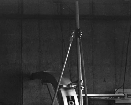
Step A: Tripod Kit (Figs. 114, 115, 116, 117 & 119)
The Tripod Kit is furnished as part of the 3-1/2 or 5-1/2-ft Horizontal Spout Extension packages. It is also available for separate order whenever additional Spout support is desired as for when 3 or 4 feet of Vertical Extensions are going to be installed.
NOTE: If Extensions are going to be used, they MUST be attached to the Spout before the Tripod Kit is mounted.

Caution
Because of the weight and awkwardness of the extended Spout, at least two people should carry-out the Spout mounting procedures.
With the desired Spout Extension(s) mounted onto the Spout, proceed to mount the Tripod Kit as follows:
1.Properly position and secure the Tripod to the top of the Lift Cylinder Post with (4 each) 3/8 x 1-1/4 CS, L and N. When correctly positioned, the Vertical Tube of the Tripod should be facing towards the rear of the Post.
3.Based on the number of feet of Vertical Extensions to be used, determine the position and direction of the Tripod Arm with respect to the Tripod Bracket. Referring to the illustrations provided, position the Arm below the Bracket for 1 or 2 feet of Vertical Extensions as shown in Fig. 115. For 3 or 4 feet of Vertical Extensions, the Arm MUST be positioned above the Bracket. In addition, for 3 feet of Vertical Extensions, the Arm MUST positioned as shown in Fig. 116. For 4 feet of Vertical Extensions, the Arm MUST be turned around as shown in Fig. 117.
On the basis of the above determination, install the Tripod Arm and Tripod Bracket over the Tripod Tube in the required position.

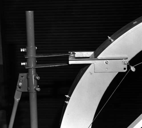
4.Align the Tripod Bracket so that its mounting holes line up with appropriate holes in the Tripod Tube in the required position. The slotted ear MUST face the front of the Harvester. Secure the Tripod Bracket with (2 each) 1/2 x 3-1/2 CS and LN. Also, secure the Tripod Bracket by tightening the (2) 5/8 x 1-1/2 CS and the (2) 5/8 N to lock the positions of the CS.
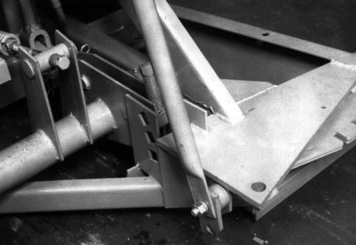
5.Loosely attach the bottom end of the Front Tripod Brace to the Tongue Cylinder Bracket. Install a 5/8 x 3 CS through the Frame, the thick end of the Tripod Anchor and the Tripod Brace as shown in Fig. 118. Secure the assembly with a 5/8 L and N.
6.Loosely attach the Right Tripod Brace to the Axle Bracket with a 5/8 x 1-3/4 CS, L and N.
7.Attach and tightly secure the Right Tripod Brace to the right ear of the Tripod Bracket with (2 each) 5/8 x 1-3/4 CS, L and N.
8.Loosely attach the Front Tripod Brace to the front ear of the Tripod Bracket using the Tripod Brace Clamp and (2 each) 5/8 x 1-3/4 CS, L and N. BE SURE to position the Clamp and Brace on the opposite sides of the Tripod Bracket ear.
9.Tightly secure the hardware at the lower end of both Tripod Braces.
10.Properly position and attach the Spout Pivot Bracket onto the Spout using the upper Spout Bracket mounting holes and existing holes and hardware in the Spout. BE SURE to delete the (4) 5/8 P from the Spout Carriage Bolts when installing the Bracket.
NOTE: The following procedure can only be carried-out after the Spout is in position to be installed and secured onto the Blower Outlet.
11.Install the Spacer into the hole in the Spout Bracket and position the Bracket between the plates of the Tripod Arm. Install a 1/2 x 3-3/4 through the Arm. Secure the 1/2 CS with a LN.
NOTE: To facilitate Tripod adjustment, rotate the Spout so that it is in-line with the Tripod Arm.
12.After the Spout (with mounted Extensions) is properly secured onto the Blower Outlet, the Tripod Arm can be adjusted (up or down) to position the Spout Bracket midway between the plates of the Tripod Arm. Once the Arm is centered, it can be secured to the Tripod by tightening the (4) CS and the (4) 5/8 N can be tightened to lock the positions of the CS. Proper attachment of the Tripod Arm accomplishes the side-to-side alignment of the Tripod. Forward and backward alignment of the Tripod is accomplished by forcing up on the Cap end of the Spout and tightening the Clamp and front Tripod Brace connection to the Tripod Bracket. If the limit of the slot in the Bracket is reached before correct Tripod and Spout alignment can be obtained, (1 of the 2) 5/8 x 1-3/4 CS should be temporarily removed and repositioned through the other hole in the Brace, after the Clamp is rotated.
11 – Factory Installed 1-foot Vertical Spout Extension & Cap Control
Step B: Vertical Extensions (Fig. 119)
The Harvester is provided with a factory-installed, 1-ft Vertical Extension. This allows the Capmotor and Spout Control Motors to be factory installed and pre-wired. When a 1-ft and/or 2-ft Vertical Extension is being installed, the additional Vertical Extension(s) should be mounted above the factory-installed 1-ft Vertical Extension. This will keep the Cap Motor and its wiring close to the Blower. A set of (8 each) 1/2 x 1-1/4 CS and LN is provided with each Extension for attaching that Extension.
NOTE: If the factory-installed, 1-ft Vertical Extension is removed and the Spout is attached directly to the Blower Outlet Flange, a special Spout Capmotor Relocation Kit MUST be obtained and installed per the information provided with the Kit.
Step C: Horizontal Extensions (Figs. 119 & 120)
Mounting procedures for either the 3-1/2-ft or 5-1/2-ft Horizontal Spout Extension packages are the same. Refer to the Tripod Kit mounting procedures, after the Extension is attached to the Spout. To mount either Extension, proceed as follows:
1.Remove and retain the Clean-out Cover(s).
2.Remove the Cap and attaching hardware from the Spout and reinstall these same parts onto the end of the Extension.
NOTE: Throughout this assembly procedure, BE SURE to install all attaching hardware from inside the Spout or Extension so that all bolt heads are located on the inside.
3.Attach and loosely fasten the Horizontal Extension Brackets to each side of the Extension with (3 each side) 5/16 x 3/4 THMS, L and N.
4.Slide the Extension with Brackets over the end of the Spout and loosely secure the Brackets to the Spout with (1 each side) 5/16 x 3/4 THMS, P, L and N.
5.Install and loosely attach the (1) 5/16 x 1-1/2 THMS into the left lower rear hole in the Spout and Extension Bracket. Install the THMS through Spout, through Extension Bracket, through Extension and secure it with (2) P, a L, N and a LN.
6.Install and loosely fasten a 5/16 x 1 THMS in the remaining (3) holes with L and N.
7.Attach and loosely fasten the Extension Spout Tie to the Spout and Extension using (4 each) 1/4 x 1/2 THMS, L and N.
8.Properly position and install the Spout Extension Brace between the Spout Flange and the Extension Brackets. Loosely attach the top end of the Brace to the Extension Brackets with (2 each side) 1/2 x 1-1/4 CS, P, L and N as shown. Mount the bottom end of the Brace to the Spout Flange and Vertical Extension Flange or Spout Clamps with (2 each) 1/2 x 5 CS and attaching hardware.
9.Make sure that the inside top end of the Horizontal Extension is slightly above the inside top end of the Spout, in the area where the two parts meet. Likewise, make sure that the Cap end of the Extension is down and properly in line (to provide a good radius) for smooth material flow against the tops of the Spout and Extension, as the material is being discharged. Once the correct alignment is obtained, all loosely attached mounting hardware can be tightly secured.
NOTE: If the Cap Control Cable is too short for the Horizontal Extension, splice a second Cable (provided) as shown in Fig. 120. Cut off and discard any excess Cable.
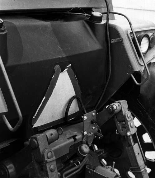
Step D: Tunnel Switch (Figs. 121, 122 & 123)
NOTE: The following instructions ONLY apply when adding a Water Tank Accessory to a Shear Bolt Model Harvester.
1.Preassemble the Vane to the Tunnel Switch. Secure the Vane with the (2) Self-drilling Screws provided.
2.Remove the Coverplate from the Spinner Chute and properly orient and attach the Tunnel Switch with (3 each) 5/16 x 3/4 CB, L and N.
3.Anchor the Plug from the Tunnel Switch to the Spinner Chute in the area shown using a Vinylcoated Clamp.
4.Route the Tunnel Adapter Harness from the Tunnel Switch along the face of the Rear Blower Sidesheet and over the corner of the Blower Frame. Anchor the Tunnel Adapter Harness in the three places shown with Vinyl-coated Clamps.
5.Using existing hardware, make the Ground Ring Terminal anchor to the Blower Frame as shown in Fig. 123. Remove the paint in this area to provide a good electrical ground.


6.Connect the Adapter Harness Single Male Plug to the Water System Control Wire coming from the Water System Control Box inside the tractor.
NOTE: The Single Female Plug in the Adapter Harness will NOT be used on Shear Bolt Model Harvesters.
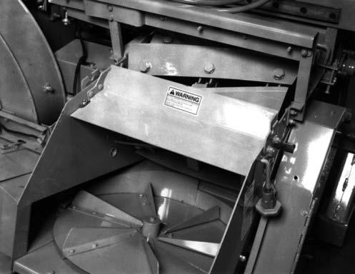
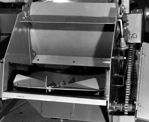
Step E: Square-holed Screens & Wet Crop Deflector (Figs. 124 & 125)
NOTE: To install a Screen or a Wet Crop Deflector, a Cam Kit MUST be ordered separately.
To install a Screen or a Wet Crop Deflector, proceed as follows:
1.Remove the Spinner Cover and the Cylinder Cover.
2.Remove the (6) Cam Hole Plugs from the Cylinder Sidesheet. Clean the debris and build-up (if present) from the inside walls of the Cylinder Sidesheets with a scraper.
NOTE: If desired and to obtain additional clearance, temporarily remove the Rear Cylinder Tie. BE SURE the Tie is replaced and properly adjust the Cylinder Cover Mounting Brackets before attempting to adjust the Cams.
3.Position the Screen or Wet Crop Deflector under the Cutting Cylinder and: a. For a Screen, insert the (6) Cam Bolts through the slots in the Screen flanges and through the left and right Sidesheets. Install the (6) Cams over the (6) Cam Bolts from the outside of the Harvester Sides. Secure the Cam Bolts with the 1/2 Nuts and L. Before the Nuts are tightened, make sure that the Cam Bolts are on the forward edges of the Screen flange slots to prevent the Screen from moving rearward during Cylinder operation. Tightly secure the Cam hardware. b. For the Wet Crop Deflector, insert the (2 each side) Cam Bolts through the holes in the Deflector flanges and through the left and right Sidesheets. Install the remaining (2) Cam Bolts through the left and right Side Sheets with the Bolt heads inside the Side Sheets. Install the (6) Cams over the (6) Cam Bolts from the outside of the Harvester Sides. Secure the Cam Bolts with the 1/2 Nuts and L. Tightly secure the Cam hardware.
4.Install the Rear Cylinder Tie and Cylinder Cover Mounting Brackets, if they were removed. Refer to the Adjustments chapter for Cylinder Cover Bracket position adjustments.
5.Replace the Cylinder and Spinner Covers and secure them.
NOTE: Refer to the Adjustments chapter for Screen adjustment procedures. BE SURE to replace the Rear Cylinder Sidesheet Tie, the Cylinder Cover and the Spinner Cover BEFORE restarting the Harvester.
Step F: Control Box Extension Harness (See Fig. 111)
An optional Control Harness Extension is available, if the Control Harness can NOT reach the Control Box. This Extension Harness may be needed for most 4-wheel drive tractors. It is installed between the Control Box and the Control Harness.
The Torque Sensor and Metal Detector models use the same eleven-wire Extension Harness. The Shear Bolt model uses an eight-wire Extension Harness. All models use a 2–wire Extension Harness with the Water Tank accessory.
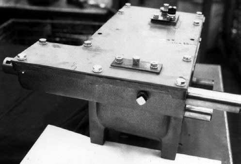
Step G: Long Cut Kit (Figs. 126 & 127)
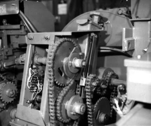
The optional Long Cut Kit provides a means of increasing the achievable Length-of-Cut by replacing the factory-provided Sprockets on the Feed Roll Drive Transmission Input Shaft and and the Attachment Drive Shaft. With all eight Knives installed, the Length-of-Cut can typically be increased to 9/16 ″. As shown in Fig. 126, the original 28T Sprocket is replaced by a 20T Sprocket. Similarly and as shown in Fig. 127, the original 40T Sprocket is replaced by a 28T Sprocket. Both Sprockets are secured to their respective Shafts with two SHSS each. The Input Chain to the Shifter Transmission and the Chain driving the Attachment Drive Torque Sensor will have to be shortened to fit the new Sprockets.
1 – Original 28T Sprocket (Item 23) to be Replaced by 20 T Sprocket in Kit - Secured with Two SHSS Supplied with Kit
2 – Attachment Driver Shaft (Item 29)
Fig. 126: Portion of Drawing From Service Parts Manual
1 – Original 40 T Sprocket (Item 24) to be Replaced by 28 T Sprocket in Kit - Secured with Two SHSS Supplied with Kit
2 – Shifter Transmission (Item 28)
Fig. 127: Portion of Drawing From Service Parts Manual
NOTE: After the correct Chain lengths have been obtained, BE SURE to adjust the Chains for proper operating tension.
Step H: Safety Chain
NOTE: Routing and anchoring an accessory 30,000 Pound Safety Chain Kit should be done in the manner shown in Transporting chapter.
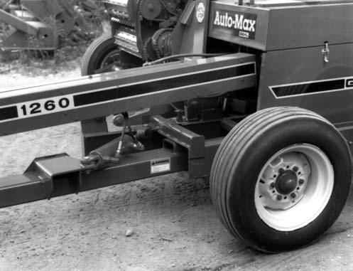
Step I: Offset Wagon Hitch (Fig. 128)
The accessory Offset Wagon Hitch is available for adapting your Harvester to reposition the Hitchplate so that the forage box pulls more directly behind the tractor when harvesting row crops. Installation of the Offset Hitch reduces side draft and helps keep the row crop attachment centered on the rows. Installation instructions are provided with the package of parts.
1 – 36″ (914 mm) Between Outside Bolts
2 – Offset Wagon Hitch Tube
3 – Hitch Tube Plates (2)
4 – Wagon Hitch Tube Clamp Plates (2) – Can also be used for towing Wagons
Fig. 128: Offset Wagon Hitch
Step J: Second Tractor Control Box
Wiring Kits
Accessory Second Tractor Control Box Wiring Kits are available for adapting the same Control Box to a second tractor. The Kit for the Torque Sensor and Metal Detector models contains a Power Supply Harness, a Control Harness, a Control Harness Mounting Bracket and two Control Box Mounting Plates. The Kit for the Shear Bolt model contains a Power Supply Harness, an Extension Harness, an Extension Harness Mounting Bracket, a Mounting Clamp, a Dust Plug, and one Control Box Mounting Plate. Refer to Control Box Mounting and Wiring procedures, steps 10a or 10b, for comparable installation details.
Step K: Highway Transport Lighting Kit
NOTE: If the Harvester is going to be transported on a public highway, a Transport Lighting Kit should be obtained and installed per details provided in the Kit.
An accessory Highway Transport Lighting Kit is available for all Harvester models. It includes Lights, Wiring Harnesses, an Outlet, and installation instructions. The Outlet allows connecting the Transport Lights of a wagon towed behind the Harvester.