11 minute read
CHAPTER 5 CONTROLS & SAFETY EQUIPMENT


This Harvester is provided with several features for operator safety and convenience.

Caution
Become familiar with and know how to use ALL Safety Devices and Controls on the Harvester (and tractor) BEFORE attempting to operate this equipment. Know how to stop Harvester operation BEFORE starting it. This Gehl Harvester is designed and intended to be used ONLY with a mounted Gehl Company Attachment. The Gehl Company will NOT be responsible for operator safety if used without a completing Attachment.
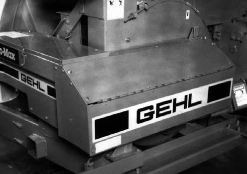
CAP CONTROL (Fig. 3)
The Spout Cap is spring-returned to the raised (up) position. Lowering the Cap (to distribute the forage from the back to the front of the forage box) is accomplished by activating the appropriate tractormounted Control Box Switch which operates the Cap Control Gearmotor.
SPOUT CONTROL (Fig. 3)
The Spout can be rotated (to distribute the forage across the width of the forage box) by activating the appropriate tractor-mounted Control Box Switch which operates the Spout Control Gearmotor.
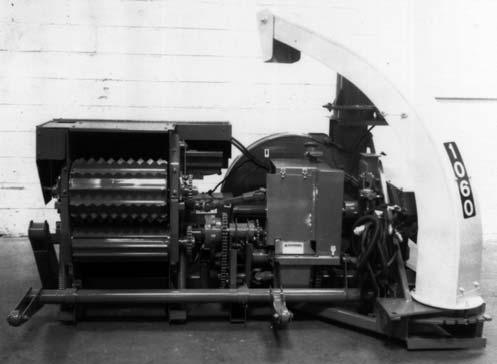
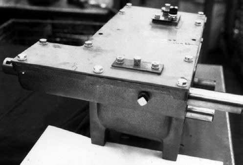
ATTACHMENT POSITIONING (Figs. 1 & 2)
Mounted Attachment positioning is accomplished by the standard 8” stroke, 3” bore, double-acting hydraulic cylinder provided. A Lift Cylinder/Knife Sharpener Selector Valve enables convenient switching between the Attachment Lift and Knife Sharpener systems.
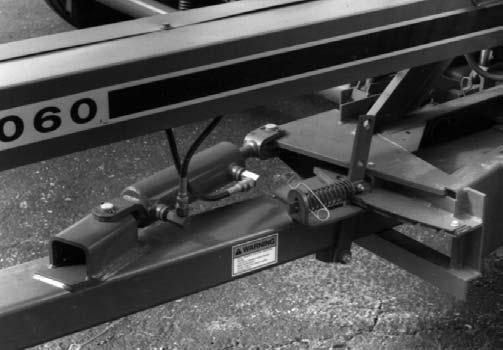
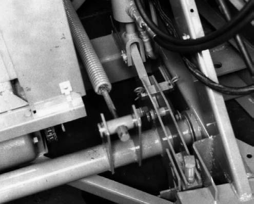
TONGUE POSITIONING (Figs. 4 & 5)
The Harvester Tongue can be repositioned manually by operating the Latch Mechanism which is linked by a Control Cord routed to the operator on the tractor seat.
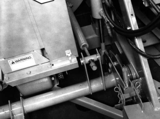

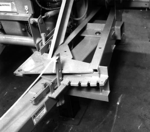
Transport Latch mechanism should be locked in the deactivated position.
Caution
When transporting the Harvester, the Latch Mechanism MUST be locked in the “transport” position, as shown in Fig. 4.
LIFT SYSTEM LOCK (Fig. 6 & see Fig. 1)
The hydraulically operated Lift System can be lockedup in order to maintain the Attachment in the “raised” position during transporting. To place the Lift System into the “Locked-up” position, first fully extend the Lift Cylinder and completely raise the Attachment. Exercise the MANDATORY SAFETY SHUTDOWN PROCEDURE (page 8) and install the Down Stop Pin into the “highest” possible (1 of 3) holes in the Lift Mechanism. BE SURE to lock the Pin in this position with the Cotter Pins provided. Then, turn the Down-Stop Bolt fully downward into contact with the Down Stop Pin.
The Tongue can be remotely repositioned by obtaining and installing a Hydraulically-operated Tongue Kit. When this Kit is installed and for field operation, the
GUARDS & SHIELDS
Wherever possible and without affecting machine operation, Guards, Shields and/or hinged Covers have been used on this equipment to protect potentially hazardous areas. In many places, Decals are also provided to warn of potential dangers as well as to display special operating procedures.
Warning
Read and thoroughly understand ALL Warnings on the unit BEFORE operating it. Do NOT attempt to operate this equipment unless ALL factory installed Guards and Shields are properly secured in place.
Implement Drive Line Guards (Fig. 7)
The Telescoping PTO Drive connection to the tractor is equipped with rotating Shields.


Warning
BE SURE that the Rotating Shield on the Telescoping Drive turns freely BEFORE starting the tractor engine.
A Guard is provided over the entire fixed-length portion of the Implement Drive Line, from the Front Bearing Support back to the Bevel Gearbox Input Shaft.
Miscellaneous Guards (Figs. 7 & 8)
Various latched and hinged Guards and Covers are provided on the Harvester to protect access points for service and/or adjustment.
Caution
BEFORE proceeding to perform any work on the Harvester and BEFORE removing or opening any Guards or Covers, BE SURE to exercise the MANDATORY SAFETY SHUTDOWN PROCEDURE (page 8). BE SURE to replace ALL Guards and Covers BEFORE resuming operation.
HITCHJACK (Fig. 9)
A Hitchjack (Jack) is furnished with the Harvester to support the machine when the tractor is disconnected as well as to facilitate aligning the Harvester Hitch Clips with the tractor Tongue during hookup.


Warning
BE SURE the Lockpin is properly seated through the holes in the Jack Tube and the Tongue Hub of the Harvester, BEFORE the disconnecting the Harvester from the tractor.
When the Jack is NOT being used to support the Tongue, remove the Lockpin and swing the Jack into its “storage” position. Wrap the Lockpin Chain around the Jack Handle (to hold it up) and then insert the Lockpin through the holes in the Jack Tube and Tongue Hub to secure it.
HYDRAULIC KNIFE SHARPENER (Fig. 10 & see Fig. 2)
The Harvester is equipped with a factory-installed Hydraulic Knife Sharpener for sharpening the Cylinder Knives and the Cutterbar. The Sharpener is powered by the same tractor hydraulic circuit used to operate the Attachment Lift Cylinder. A Selector Valve is provided to conveniently switch between the Lift Cylinder and Knife Sharpener.

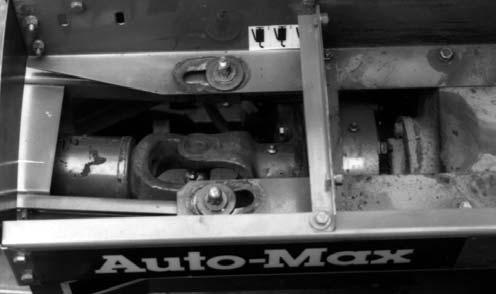
OVERRUNNING CLUTCH (Fig. 11)
The Harvester is provided with an Overrunning Clutch assembly on the input to the Bevel Gearbox. The Overrunning Clutch isolates the tractor PTO from the Harvester Drive Line and therefore eliminates torque loading and strain on the tractor PTO brake.
Shifter Transmission Control
The Shifter Transmission (and Electric Clutch) is used to stop the Feed Rolls and the Attachment, to run them forward (to bring the crop into the Cutting Cylinder), or to run the Feed Rolls backwards (to reverse plugging material out of the Feed Roll area). Shifting the Transmission is accomplished by activating Switches on the tractor-mounted Control Box. Refer to the Operation chapter in this manual for specific details.
Caution
BEFORE leaving the tractor, ALWAYS turn the Control Box Keyswitch to OFF and remove the Key and take it with you for your own safety and to avoid unnecessary drain on your tractor battery.
TELESCOPING PTO COUPLER LOCK (See Fig. 9)
The standard 1-3/8″ Telescoping PTO Drive is equipped with a Spring-loaded Locking Device to positively lock it onto the tractor PTO shaft. Depress the Locking Device against the Spring tension and slide the Yoke onto the tractor PTO shaft. Release the Locking Device and move the Yoke ahead or back until the Lock engages in the groove on the tractor PTO shaft. The optional 1-3/4″ Telescoping PTO Drive is provided with two Bolts for securing the Yoke onto the tractor PTO shaft.
Warning
BE SURE the Telescoping PTO Connection is properly secured to the tractor PTO shaft BEFORE starting the tractor. Also BE SURE that the Telescoping Drive Shields rotate freely BEFORE starting the tractor.
SAFETY CHAIN & TRANSPORT LIGHTING (Fig.12)
As required or when desired, the Harvester should be equipped with a safety chain for operation on public highways. Refer to the Optional Features & Accessories chapter for ordering information. The safety chain should be attached to the tractor and Harvester as shown.

Fig. 12
Caution
ALWAYS follow state and local regulation regarding use of a safety chain and transport lighting when towing farm equipment on public highways. ONLY a safety chain (NOT an elastic or nylon/plastic tow strap) should be used to retain the connection between the towing and towed machines, in the event of separation of the primary attaching system. BE SURE to check with local law enforcement agencies for your own particular regulations. Unless otherwise prohibited, use a Slow-moving Vehicle Emblem.
Chapter 6 Operation
NOTE: This chapter is divided into four separate sections. The first section pertains to all Harvester models. The second section only pertains to a Shear Bolt model Harvester. The third section only pertains to a Torque Sensor model Harvester. The fourth section only pertains to a Harvester with Metal Detector system.
All Harvester Models
General Information Warning
BEFORE starting the tractor engine and running the Harvester, review and comply with ALL applicable recommendations set forth in the SAFETY chapter.
Emergency Shutdown
In an emergency or in case a foreign object enters or becomes lodged in the Feed Roll area, STOP Harvester operation IMMEDIATELY by disengaging the tractor PTO.
Start-up WARNING
BE SURE ALL Guards and Shields are properly secured in place BEFORE starting the tractor engine and operating the Harvester.
ALWAYS engage the tractor PTO at idle speed when starting-up the Harvester. The first time the Harvester is being operated, shift the Feed Roll Transmission through its three positions to make sure that all mechanisms are operating properly. In addition, operate the Lift System and the Spout and Cap control systems to verify proper operation.
NOTE: To protect the Drive Line components of both the Harvester and the tractor, avoid engaging the tractor PTO at faster than idle speed.
Warning
When any part of the Harvester other than the Feed Rolls or Attachment becomes plugged, stop Harvester operation IMMEDIATELY by moving the Feed Roll & Attachment Selector Switch to NEUTRAL or OFF. Then, disengage the tractor PTO and wait for ALL movement to STOP. Then, exercise the MANDATORY SAFETY SHUTDOWN PROCEDURE (as described on page 8). BEFORE leaving the tractor seat to remedy the plugging problem, turn the Control Box Power Keyswitch to OFF, remove the Key and take it with you.
Entering the Crop
NOTE: The PTO should be brought-up to the rated 1000 RPM before entering the crop and then maintained at that speed while harvesting.
To maintain the rated RPM, choose the correct tractor gear position to adjust ground speed rather than the tractor throttle.
Sharp Cutting Cylinder Knives and proper Cutterbar adjustment will provide for more efficient Harvester operation and will reduce horsepower waste.
Leaving the Crop
Maintain the rated RPM for a short time after leaving the crop. This will allow the Harvester Blower, Cutting Cylinder and Spout to be emptied. After the forage stops coming out of the Spout, the PTO can be disengaged or the tractor throttled down.
Unplugging Warning
When any part of the Harvester other than the Feed Rolls or Attachment becomes plugged, stop Harvester operation IMMEDIATELY by moving the Feed Roll & Attachment Selector Switch to NEUTRAL or OFF. Then, disengage the tractor PTO and wait for ALL movement to STOP. Then, exercise the MANDATORY SAFETY SHUTDOWN PROCEDURE (as described on page 8). BEFORE leaving the tractor seat to remedy the plugging problem, turn the Control Box Power Keyswitch to OFF, remove the Key and take it with you.
Blower
If the Blower becomes plugged with chopped forage, proceed as follows to clear it:
1.Exercise the MANDATORY SAFETY SHUTDOWN PROCEDURE (as described on page 8).
2.Before cleaning-out the Blower, wait for the Cylinder to stop turning. Observe the Blower Shaft to determine if the Blower is still rotating.
NOTE: Even if the Blower Outlet is plugged, the Fan could continue to rotate.
3.The Spinner Chute can be removed to help gain access to the bottom portion of the Blower.
4.After the forage has been cleaned-out of the Blower and the Fan turns freely, check the Blower Outlet to insure that it is NOT also plugged.
5.If the Blower Outlet is plugged, use a rod to poke down from the top through the Spout Cleanout Holes.
6.After the Fan is free to rotate, replace the Chute and Cleanout Covers. Close the Belt Guard Shield and latch it.
Cylinder
If the Cutting Cylinder becomes plugged with forage, proceed as follows:
1.Exercise the MANDATORY SAFETY SHUTDOWN PROCEDURE (as described on page 8).
2.Inspect the Cylinder by removing the Cover. Check to see if the Knives are wedged with forage. If they are hung-up, do the following: a.Pry the Cylinder backward as far as possible so that the Cylinder can build-up momentum before it enters the crop. b.Reinstall and secure the Cylinder Cover and Guards. c.Start the tractor, run the engine at 3/4 to full throttle and engage the PTO to clear the plug; this may partially shear the Impact Pins. d.Again, exercise the MANDATORY SAFETY SHUTDOWN PROCEDURE (as described on page 8) and then check the Cylinder to make sure it is unplugged. e.Inspect the Main Drive Impact Pins (and replace them, if necessary) following the procedure as described under the “OVERLOAD PROTECTION - Main Drive Line” topic, later in this chapter.
Warning
After the Cylinder is freed and cleaned-out and the Impact Pins have been inspected (and replaced), reinstall all Guards and Covers BEFORE resuming Harvester operation.
3.Insert the Control Box Key, turn the Power On, start and idle the tractor, engage the PTO, bring the tractor up to rated operating speed, shift to “Forward” and resume harvesting.
Spout
If the Spout becomes plugged with chopped forage, proceed as follows:
1.Exercise the MANDATORY SAFETY SHUTDOWN PROCEDURE (as described on page 8).
2.After all Cutting Cylinder and Blower movement has STOPPED, remove the Cleanout Cover from the base of the Spout.
3.Remove any plugging material which may be wedged inside the Spout or Spout Extension through the Cleanout Cover(s).
4.Check and, if necessary, unplug the Blower and Cylinder areas. Refer to the information under the Blower and/or Cylinder topics, earlier in this chapter, to unplug these areas.
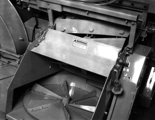
Spinner & Spinner Chute
The Spinner and Spinner Chute might become plugged if the tractor PTO RPM is NOT maintained. To clean-out the Spinner and Chute, proceed as follows:
1.Exercise the MANDATORY SAFETY SHUTDOWN PROCEDURE (as described on page 8).
2.Remove the Spinner Cover, open the Blower Belt Guard and remove the Spinner Chute. To remove the Chute, first unlatch it. Next, shift the Chute about 3/4″ (19 mm) to the right. Then, pull the left end away from the Blower Housing and shove the Chute to the left while removing it.
3.Remove the forage which is built-up in the Chute and on the Spinner.
4.Slowly rotate the Spinner (by hand) to insure that it turns freely.
5.Check also that the Blower turns freely and make sure that the Spout is unplugged. Refer to the information under the Blower and Spout topics earlier in this chapter to unplug these areas.
6.Replace the Spinner Cover and Chute and close and secure the Blower Belt Guard before resuming operation.
Harvesting Capacity
The accompanying Table is intended as a guide to help the customer anticipate his machinery requirements in order to achieve his harvesting program. The figures are based on actual field tests conducted by the Gehl Company in corn yielding 10 Tons to the acre at 50% moisture. These figures may also be used to calculate hay harvesting at 50% moisture and yielding 4 Tons to the acre.
These figures represent an uninterrupted run and most customers should multiply them by 0.7 to account for time spent changing wagons, traveling headlands and any other non-harvesting activities.
“Tractor Horsepower” is the PTO dynamometer rating. From it was subtracted a suitable amount for pulling the tractor itself, the Forage Harvester and a half-loaded wagon across the ground at a speed appropriate for the listed capacity.
NOTE: For highest achievable efficiency, keep the Feed Rolls full and keep the Knives sharp and set up to a sharp Cutterbar.
Table of Harvesting Capacities
Overload Protection
Main Drive Line (Fig. 13)
The Main Drive, which is connected through an Overrunning Clutch assembly to the Input Shaft of the Bevel Gearbox, is protected from “sudden start” impact damage by a flanged connection and Impact Pins. The Flange is secured to the Overrunning Clutch with (2) Impact Pins (5/16 x 3-1/4 Grade 5 Cap Screws) with double-Nuts (two 5/16 Hexagon Nuts per Pin). These Pins are capable of transmitting approximately 675 hp and are designed to break only under a high impact caused by the engagement of the tractor PTO while the tractor is running at a high RPM. The Flange is equipped with a Grease Fitting in the Pilot Area to prevent the Shaft from seizing; the Fitting MUST be greased daily. Additional Impact Pins are provided in the Toolbox.
NOTE: ALWAYS use double-Nuts (Two 5/16 Hexagon Nuts) on each Impact Pin to prevent them from loosening.
Spinner Drive (Fig. 15)
The Spinner Drive is protected by two (2) 5/16 x 1 Grade 2 Shear Bolts which are installed in the Spinner Disc. BE SURE to remove the cause of the overload BEFORE attempting to resume operation. The sheared-off portion of the Shear Bolt will be found in the material laying on the Spinner Disc and should be removed.
Lower Feed Roll Drive (Fig. 14)

The
Feed
Drive is provided with
Hydraulic Knife Sharpener
A Hydraulic Fuse is included in the Knife Sharpener pressure line.
This Fuse prevents over-speeding the Sharpener Motor by limiting the oil flow to a maximum level. Refer to the Knife Sharpener topic in the Service chapter for additional resetting information.
Control Boxes (See Figs. 17 & 18)
The entire electrical system is protected by Circuit Breakers within the appropriate Control Box. To reset a Breaker, clear the trouble in the system first. Then, depress the Breaker Button.
NOTE: After a Breaker is tripped-out, it takes about 10 seconds before the Breaker can be reset.