20 minute read
CAUTION

BE SURE to exercise the MANDATORY SAFETY SHUTDOWN PROCEDURE (page 8) BEFORE proceeding.
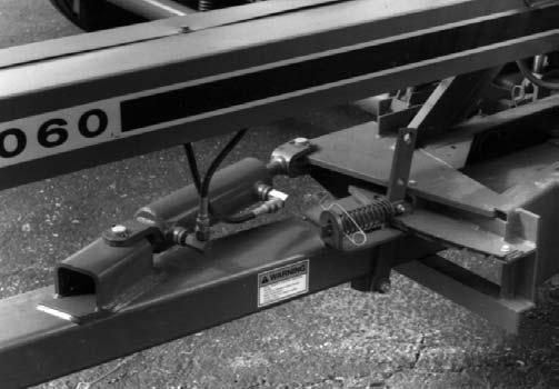
1.The space between the Cutterbar and Scraper will first have to be cleaned of debris. Then, move the Cutterbar forward to the end of its adjustment slots.
2.After implementing the proper precautions, remove the Spinner and Cylinder Covers. For better access, remove the (4) Bolts holding the Sidesheet Tie and remove the Tie.
3.After the Screen (if present) is also removed, loosen the (3) Bolts which secure the Knife to the Cylinder Headers.
6.Adjust the Cutterbar and Knives following the details given in the Adjustment chapter of this manual.
NOTE: BE SURE to watch the balancing of the Cutting Cylinder Knives when mixing old and new Knives. An old Knife should ALWAYS be balanced on the opposite side of the Cylinder with another old Knife and a new Knife should ALWAYS be balanced on the opposite side with another new Knife.
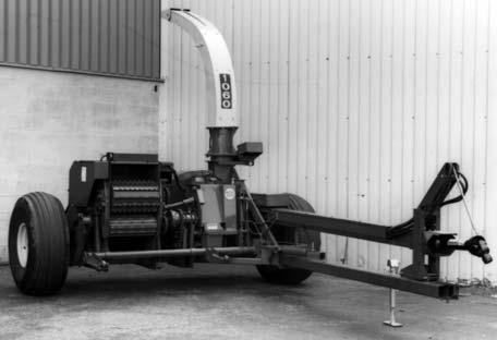
SPOUT (Fig. 64)
A replaceable Liner is built into the Spout which can be removed by taking-out (8) Plow Bolts. After the hardware is removed, the Liner can be guided through the Spout and removed from the Cap end, without taking the Spout off the Blower Outlet. To facilitate removal, it may be necessary to temporarily remove a Horizontal Spout Extension, if present. New Liner installation is in reverse of old Liner removal. As necessary, remove any or all of the Cleanout Hole Covers for access to the Liner and Plow Bolts.
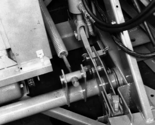
the replacement Knife to the Cylinder
NOTE: Knife Bolts are threaded into Special Nuts which are positioned in the Header slots with their thin sides facing the left side of the Harvester.
5.After the Knives and Cutterbar are adjusted, replace the Sidesheet Tie following details under the Cylinder Cover subtopic in this chapter.
KNIFE (& CUTTERBAR) SHARPENING WARNING
Because the tractor engine will be running while the Knives or Cutterbar are being sharpened, BE SURE that the Telescoping PTO Drive Connection is removed from the tractor PTO shaft.
NOTE: To facilitate rotating the Cylinder Knives while sharpening them, BE SURE to suspend the Harvester Telescoping Drive with the Spring provided. In addition, make sure that the Electric Clutch is open.
General Information
The Knife Sharpener is designed to operate with any tractor capable of delivering a continuous 8 gpm supply of oil at 1500 PSI (10500 Kpa). The hydraulic circuit is equipped with a Check Valve for the Knife Sharpener Motor which prevents running the Motor backwards. Thus, hydraulic hose hook-up to the tractor has NO particular orientation except to establish which way the tractor Remote Control Lever has to be moved to run the Sharpener Motor. A Hydraulic Fuse is included in the pressure line. This Fuse allows NO more than 9 gpm to flow thru it. Quantities in excess of 9 gpm cause the Fuse to snap shut and stop the Motor, and thus prevent overspeeding the Grinding Stone. If the Fuse snaps shut, it can be reset. This is done by moving the tractor Remote Control Lever momentarily to the position opposite of the running position. Like an electric circuit, if everything is in order and the Motor will NOT turn, the Fuse is tripped-out and MUST be reset to restore Motor operation.
Since few tractors deliver the same quantity of oil (gpm) to the remote circuit and since the gpm determines the RPM of the Hydraulic Motor, the first use (and first use only) with any unproved tractor will require one of two settings to be determined. On Open Center System tractors, the throttle setting will determine the Sharpener Motor RPM while on Closed Center System tractors, the Needle Valve will determine the RPM and thus, require setting.
The type of system used in your tractor will be found in your tractor’s Operators Manual.
Open Center System Tractors
NOTE: The Needle Valve is NOT used with this type of tractor and should be left wide open. If it has been closed-down for use on a Closed Center System tractor, open it (counterclockwise).
To determine the tachometer setting at which the unit should always be operated, first, idle the tractor at low idle and engage the remote control lever, starting the Sharpener Motor. Increase the tractor RPM until the Motor cuts out. The Hydraulic Fuse has tripped at around 9 gpm. A tachometer reading of 100 RPM less than this cut-out value is the proper speed at which the Sharpener should be operated with this tractor.
When you are ready to grind the Knives or Cutterbar, set the tractor throttle to this tachometer setting and engage the remote control lever.
Cold hydraulic oil can trip the fuse at your “normal” tachometer setting. BE SURE to run the Sharpener at lower than the rated speed, BEFORE starting to sharpen the Knives or Cutterbar, until the oil is warm. Once the oil is warmed-up, the Sharpener can be operated at the “normal” tachometer setting to grind.
NOTE: DO NOT try to operate above this setting as it will cause frequent tripping-out of the Hydraulic Fuse.
Closed Center System Tractors
The throttle will have no control over the gpm on these tractors.
1000 RPM on the tachometer will be a good spot to run while using the Needle Valve to control the oil flow.
To find the proper setting for your tractor, turn the Valve shut (full clockwise) and back it off 2 turns. Engage the remote control lever, to start the Sharpener Motor. Open the Needle Valve slowly until the Motor stops. The Hydraulic Fuse has tripped-out at 9 gpm. Close the Needle Valve 7/8 turn (clockwise) and gently lock it in place with the Jam Nut. Reset the Hydraulic Fuse. Now, the system is permanently set for operation with this Closed Center System tractor.
Most new tractors have a readily accessible flow control of their own and you may prefer to use it. Its setting would be accomplished in a manner similar to the one described above. A scribe mark on the dial of the control, below the ’’Trip-out’’ point, will make it easy to reset without trial and error if it is required to move the control for other operations. Remember, however, that the Gehl Needle Valve and the tractor control are interdependent and a change in either between usages will effect the RPM of the Hydraulic Motor.
On some tractors the remote control lever is either spring-loaded to neutral or will kick out under low hydraulic pressures. These levers will have to be tied, with wire or rope, to prevent undesired disengagement.
Preparation (Fig. 65)
The Selector Valve is mounted on the Attachment Lift Cylinder, near the front of the Toolbox. Switch the Selector Valve to the Knife Sharpener circuit.
Unlatch the Sharpener Cover and tip it forward over the Feed Roll Housing. Remove the Spinner and Cylinder Covers. Clean crop and debris from the undersides of the Knives so the Lower Guide Rollers can operate smoothly. In addition, BE SURE that the top surface of the Sharpener Rails are also clean. Remove the Draw Rod from its storage position.
NOTE: Before operating the Knife Sharpener, make sure the entire unit is properly lubricated; the Sharpener has two Grease Fittings.
Cylinder Knife Sharpening (Fig. 66)
Warning
BEFORE operating the Knife Sharpener, remove the Telescoping Drive connection from the tractor PTO shaft and turn the Control Box Keyswitch to ’’OFF’’ and remove the Key. ALWAYS wear Safety Goggles (furnished in Toolbox) when operating the Knife Sharpener.
With the Carriage at the storage end of the Rails and using a gloved left hand, turn the Cylinder and draw the Carriage toward the Knife until the Knife is caught between the two sets of Roller Guides under the Stone. One set of Rollers bears-down against the top side of the Knife while the other set of Rollers bears-up against the bottom side of the Knife. A curved ’’lead-on’’ Plate is also provided to help rotate the Knife into position between the Roller Guides. Lower the Stone until it just contacts the Knife. Move the Carriage all the way across the Knife to make sure that it travels freely. Then, return the Carriage to the ’’storage’’ side of the Rails.

Start the Sharpener with the tractor remote control lever and make the first pass with the Stone set according to the information in the preceding paragraph. Make one pass each way on each Knife. Use a 1/8 turn of the Stone Adjustment Knob for each new cut but only after all Knives have been ground with the same number of passes at the previous setting. Totally grinding one Knife at a time will produce cutting edges at various radii which will make a close Cutterbar setting to all of the Knives impossible.
After making a complete circuit of all the Knives with one Stone setting, the Stone itself will have worn away. This means that the last Knife of the circuit will NOT be ground-down quite as much as the first Knife in the circuit. A good technique for overcoming this problem is to start the second circuit on the last Knife to be ground on the first circuit, i.e. after finishing the last Knife, turn the Stone down 1/8 turn of the Knob and begin grinding on this same Knife to start the next circuit. This Knife now becomes the first Knife on the new circuit and you should then stop and start this time on what was the second to the last Knife on the first circuit. Thus the starting point will work its way around the Cylinder with each succeeding pass. A chalk mark identifying each starting Knife as it comes up will help you to keep yourself straight.
NOTE: Traverse the Carriage in a smooth movement across the entire length of the Knife to prevent burning and to insure a smooth, uniform grind.
Cutterbar Sharpening (Figs. 67, 68, 69 & 70 & see Fig. 58)
A Cutterbar (Shear Bar) does NOT need sharpening just because it is worn but rather, because it becomes improperly worn. The Gehl Company manufactures its Cutterbar so that, if it is set up close to sharp Knives, it will wear ’’sharp’’ and ’’parallel’’ to the crop sliding across it. This is shown in the illustration provided.
As long as the tungsten carbide facing provides a nice sharp lip to the cutting edge of the worn corner, the Cutterbar is as good as ’’brand new’’ (even better than ’’brand new’’).
If the Cutterbar wears improperly, as shown, where NO sharp edge exists to act as a scissor blade for the Cylinder Knives, the Knife Sharpener can be used to renew the Cutterbar edge.
To understand the function of the Sharpener, realize that the Cutterbar is set at an angle to the incoming crop as shown. To renew the cutting edge, the Cutterbar is sharpened so that it parallels the crop sliding over it.
To set-up the Cutterbar for sharpening, proceed as follows:
1.Place the Sharpener Carriage in ’’storage’’ position at the left side of the Cylinder.
2.Raise the Stone approximately 3/4” (19 mm) higher than the setting used for Knife sharpening.
3.Loosen the 1/2” Nut which secures the Elevator so that it is free to move up or down in the slot. Remove the 3/8 x 3-3/4 Carriage Bolt from the right side. Then, place the Cutterbar into the location shown while orienting it in the same position and direction as it was when removed from the Harvester. When properly oriented, the edge to be sharpened will be closest to the Sharpener Stone. With the Cutterbar correctly oriented, place the innermost of the two left side horizontal Cutterbar holes onto the stub of the Cutterbar Elevator.
4.While holding the right end of the Cutterbar approximately 2” (51 mm) above the Support as shown, pull the Sharpener Carriage to a position where the Stop Plate on the Carriage is to the right of the Elevator. Make sure one of the Cylinder Knives is in place between the Roller Guides.

5.Lay the Cutterbar on the right side Support and reinstall the 3/8 x 3-3/4 Carriage Bolt and tighten the Nut until the Cutterbar is lifted clear of the Cylinder Knives on the left side.
6.Move the Carriage over to the right end of the Rails (raise the Stone some more if necessary) and make sure that one of the Cylinder Knives is in place between the Roller Guides.
7.With the Carriage positioned over the right end of the Cutterbar, lower the Stone to a distance of approximately 1/16” (1.5 mm) from the Cutterbar.
8.With a 1/16” distance established on the right side, move the Carriage to the left end of the Cutterbar. NOTE: BE SURE that the Carriage is moved over only as far as the Stop Plate will allow. The Stop Plate prevents the Cutterbar from being ground too far to the left end which would result in removing a surface which is contacted by the Adjustment Cam. BE SURE that the Carriage Stop Plate is on the Cylinder Knife side of the Plate which is attached to the Cutterbar Elevator Mechanism or it will NOT be possible to draw the Stone Carriage across the Knives after the left side is set.

BEFORE operating the Knife Sharpener, remove the Telescoping Drive connection from the tractor PTO shaft and turn the Control Box Keyswitch to ’’OFF’’ and remove the Key. ALWAYS wear Safety Goggles (furnished in Toolbox) when operating the Knife Sharpener.
NOTE: Before operating the Knife Sharpener, make sure the entire unit is properly lubricated; the Sharpener has two Grease Fittings.
9.Tighten the 3/8″ Nut on the Carriage Bolt until the left end of the Cutterbar is brought to a distance of 1/16″ from the Stone and then, stop tightening the 3/8 Nut.

10.With the Cutterbar levelled below the Stone, tighten the 1/2″ Elevator Nut (above the Front Rail) to secure the position of the Elevator.
11.Move the Carriage to the center of the Cutterbar and eliminate any downward bow to the Cutterbar (if present) by further tightening the 3/8 Nut on the Carriage Bolt until the center of the Cutterbar is at the same 1/16” distance from the Stone as the two ends were.
12.Start the Sharpener Motor and lower the Stone into contact with the Cutterbar until sparks appear. Take the full stroke on each pass across the Cutterbar and crank the Stone down about 1/8 turn after each pass. Continue to make passes across the Cutterbar until NO roundness remains on the cutting edge and until the Tungsten Carbide-facing meets the cutting edge all the way across the entire length of the Cutterbar. It is NOT essential that the ground-down bevel be absolutely straight. However, if the Cutterbar setting was NOT made exactly correct, the bevel can always be adjusted by running the Stone across the least ground portion of the Cutterbar until the bevel is ’’true’’.
13.Do NOT grind any more than is necessary to restore the sharp edge and do NOT grind more than halfway down. This could cause the Cutterbar to become too weak to support the cutting load.
14.Sufficient grinding will remove all of the notch in the cutting edge on the right end of the Cutterbar. This notch acts as a lead-in for the tilted Knives preventing the pointed leading edge of the Knife from driving into the top of the Cutterbar.
NOTE: Always restore the notch on the right end of the Cutterbar (when it has been removed by the Sharpening Stone) before attempting to reinstall and adjust the Cutterbar. Use a benchmounted grinder to restore the notch.
longest lasting Knife edges, the Stone be set to provide a clearance of 1/32″ and 1/16″ between the Heel of the Knives (trailing edge of the beveled surface) and the Cutterbar. This is the factory setting. So that you may check this clearance, a Template has been included with the Sharpener and stored in the Toolbox. The drawing provided shows how it is used and what to look for.
Lay the Template across the cutting edges of any two ground Knives and parallel to the Cylinder Side Sheets. Check the gap between the ground surface and the Template. Best performance will be obtained if the gap on a fully ground Knife measures from 1/32 to 1/16″ The bevel on a new, unground Knife will measure about 1/16″. Grinding with the factory setting might produce two bevels until the original bevel has been removed.
15.After sharpening Cutterbar, BE SURE to remove it from its sharpening position, replace it into its operating position, lower and secure the Elevator and store the 3/8 x 3-3/4 Carriage Bolt.
Storing Sharpener (See Fig. 65)
After sharpening is finished, return the Carriage to the storage position. Replace the Draw Rod Handle into its storage hole, replace and secure appropriate Guards and Covers and switch the Selector Valve back to the Lift Cylinder circuit.
Make Cutterbar, Knives and Screen adjustments, as applicable, following details given in the Adjustments chapter.
Sharpener Adjustments
Stone Angle (Figs. 71 & 72 & see Fig. 66)
The Knife Sharpener has a limited adjustment to provide the correct Knife Heel-to-Cutterbar clearance. We recommend that, for the highest quality cut and the
If adjustment is necessary because of too much Heel gap, the Roller Guide should be moved rearward in its slots. If there is too little gap or heel contact, the Roller Guide should be moved forward in its slots. Moving the Block half the length of the slot will change the Heel gap by about 1/16″ (1.5 mm). BE SURE that both Lower Roller Guides are touching the Knife before retightening the Block Bolts.
NOTE: After the Roller Guide Block position is relocated, the Upper Roller Spring tension MUST be readjusted.
Guide Arm & Roller Adjustment (Fig. 72)
The only requirement for adjustment of the Roller Guide Arm is that both of the Rollers MUST be touching the Knife when both are positioned below the Knife. To get both Rollers to touch, loosen the Front Guide Block Bolt and rotate the Roller Guide assembly. If both Rollers are NOT made to touch the Knife, a jump will be made in the surface of the sharpened Knife when one or the other of the Rollers leaves the Knife, at the end of the stroke, allowing the other Roller to become the guide.
Rail Alignment (Fig. 73 & see Fig. 66)
To check Rail alignment, first position the Sharpener Stone over the left corner of a Knife. Using the Motor Position Adjustment Knob, adjust the Stone position for a measured gap of 1/8” (3 mm) from the Knife and position it over the right corner of the Knife. Measure the clearance between the Knife and Stone on this side; it should also be 1/8”. If the clearance is more or less than 1/8”, change the height of the right end of the Rear Rail by rotating the Adjusting Cam on the Right Rear Post supporting the Rail.
The forward and back snugness of the Stone Carriage is controlled by Bolt and Spring assemblies on the Front Right Post and Rear Left Post. Loosen the Locking Nuts on the Bolts which attach the front and rear Rails to their respective Posts. Then, using the Rail and appropriate sized allen wrench, rotate the Rail Attachment Carriage Bolt clockwise to obtain more clearance between the Rollers or counterclockwise to reduce the clearance between the Rail and Carriage Rollers. After the desired clearance is obtained, retighten the Locking Nuts.
Spring Plate, Spring & Upper Roller Adjustments (See Fig. 66)
The Upper Roller tension for both Rollers MUST be reset whenever the Lower Roller Guide Block is repositioned. Begin by positioning the Sharpener Carriage at the point on the Rails where the Right Upper Roller is next to (but NOT on) the right end of one of the Knives. Loosen the Adjustment Bolt so that all Spring tension against it is released. Next, move the Spring assembly up or down in its slots to bring the bottom of the Roller flush with the bottom side of the Knife. After tightening the Bolts in the slot, tighten the Adjustment Bolt until the bottom of the Roller is approximately 1/16” (1.5 mm) below the top surface of the Knife. Lastly, retighten the Locking Nut to fix the Roller position. Repeat this same procedure for the Left Roller on the left end of the same Knife.
Sharpener Carriage Removal (See Fig. 69)
It may be desirable to remove the Sharpener Carriage from the Rails to facilitate Stone replacement. To remove the Carriage, first temporarily remove and retain the Stop Plate which is secured with (2 each) Carriage Bolts and Lock Nuts. With the Stop Plate removed, the Sharpener Carriage can be guided-off the right end of the Rails.
Remote Grease Lines
Several Remote Grease Lines are provided on the Harvester to facilitate lubrication of otherwise difficult to reach relubeable Bearings. If a Remote Grease Line is damaged or broken, it can be replaced by ordering a Tubing Kit (Gehl #065185).
Procedures for Grease Line replacement are covered in Instructions packaged with the Kit.
Shifter Transmission
NOTE: Shifter Transmission component repairs and replacements should only be attempted by (or under the direction of) an authorized Gehl equipment dealer. The Transmission is a mechanism which requires special tools and training to attempt repairs; only your Gehl dealer has the facilities and trained personnel to provide this service.
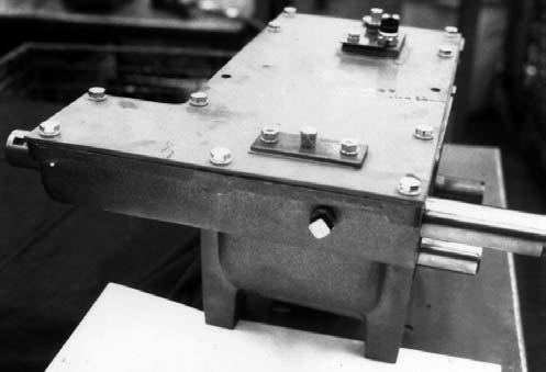
SPEED MONITOR (Fig. 74)
NOTE: The Speed Monitor is NOT used on Shear Bolt models.
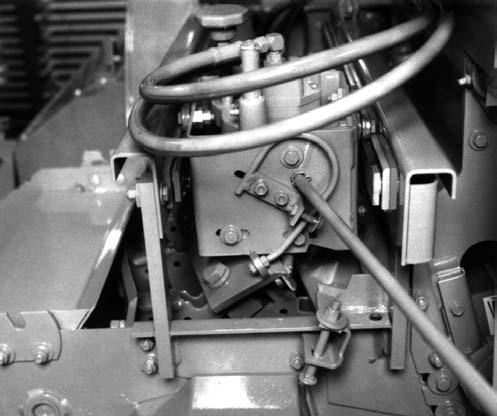
The Blower Speed Monitor Module is NOT repairable. If it is NOT operating properly, your dealer will have to determine if it MUST be replaced.
The Blower Speed Monitor Module is an integral part of the Spinner Gearbox Cover. When replacing the Spinner Gearbox Cover, make sure that the Cover is installed so that the Magnetic Pickup of the Module is directly over the Horizontal Shaft Gear. Also, to prevent damage to the Magnetic Pickup, a Gasket MUST always be present between the Gearbox Housing and the Cover.
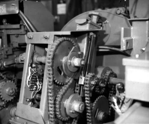
Drive Chain Idler tension, perform the following steps. While holding-up on the Latch, force the Idler Sprocket Yoke down until a hole (in the Tube) appears below the Latch. Then, insert a 1/8” diameter pin (such as a nail) thru the hole in the Tube to retain the Yoke in that position. Then, the Drive Chain can be uncoupled and removed.
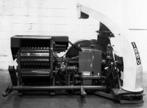
SPINNER (Figs. 75 & 76 &
The Spinner is linked by a direct Chain drive to a Sprocket on the end of the Cutting Cylinder Shaft. When the Drive Chain is uncoupled and removed, the Spinner should be free to rotate (by hand). To release the Spinner
Drive Chain
For access to the Drive Chain, Tensioning Mechanism, the Drive and Driven Sprockets, remove the Spinner Drive Guard. Access to the Spinner Disc and Paddles, is gained by removing the Spinner Cover.
NOTE: The Gearbox is packed at the factory with 1 U.S. Quart of lithium base grease. BE SURE to restore the proper amount of grease after performing service inside the Gearbox. Refer to the Lubrication chapter for additional details.
Disc & Paddles
To remove the Spinner Disc, Paddles and Hub, proceed as follows:
2.Remove the Spinner Disc assembly, by removing the two Shear Bolts attaching the Disc assembly to the Spinner Hub. Then, lift the Disc away from the Hub. Another method is to remove the Cap Screw from the top end of the Vertical Shaft and lift the Hub and Disc assembly off the Vertical Shaft.

3.To remove each Paddle from the Disc, remove the (2) fasteners from each Paddle.
Telescoping Pto Drive Warning
NEVER attempt to mix the halves of a 1-3/8 Drive with the halves of a 1-3/4 Drive. Each of the halves of the two Drive assemblies are manufactured to different lengths which if mixed, could cause the Drive to separate while it is turning and thus prove to be very hazardous.
NOTE: Besides the personal hazard of intermixing 1-3/8 and 1-3/4 Drive halves, the consequence of incompatible operation of the two improper halves could cause permanent damage to the Drives. To prevent mixing Drive halves, the Male and Female splines and the Rotating Guards on 1-3/4 Drives are manufactured opposite those on 1-3/8 Drives.
TIRES & WHEELS WARNING
The GEHL Company does NOT sell replacement Tires. In addition, Tire mounting, repair and replacements should ONLY be attempted by a qualified tire manufacturer’s representative or by properly trained personnel following the tire manufacturer’s instruction. If you do NOT have such instructions, contact your tire dealer or the GEHL Company. In addition, inflating or servicing tires can be dangerous. Whenever possible, trained personnel should be called to service and/or mount tires. In addition, do NOT place fingers on tire bead during inflation; serious injury or amputation could result! In any event, to avoid possible fatal or serious injury, follow the safety precautions below:
• BE SURE the Rim is clean and free of rust. Lubricate both the tire beads and rim flanges with a soap solution. Do NOT use oil or grease. Do NOT weld, braze, or otherwise attempt to repair and use a damaged rim.
• Use a clip-on tire chuck with a remote hose and gauge which allows you to stand clear of the tire while inflating it.
• NEVER inflate beyond 35 PSI (240 kPa) to seat the beads. If beads have NOT seated by the time the pressure reaches 35 PSI, deflate the assembly, reposition the tire on the rim, relubricate both parts and re-inflate it. Inflation pressure beyond 35 PSI with unseated beads may break the bead or rim with explosive force sufficient to cause fatal or serious injury.
• After seating the beads, adjust the inflation pressure to the recommended operating pressure listed.
Check the Forage Harvester Tire pressure after every 50 hours of operation. Tires should be inflated to appropriate pressure listed in the table. Wheel bolt torques should also be checked after every 50 hours of operation and tightened with 90 ft-lb (124.5 N-m) torque.
Tire (Inflation) Pressures
Test #2 - A minimum of 8-1/2 volts MUST exist across the Electric Clutch wires
If the voltage readings of tests 1 and 2 are NOT obtained, check all Plugs and connections and find a source, closer to the tractor battery or starter cables, to move the Control Box Power Supply lead wire connections to.
Because the wiring system in most tractors is too light, it will normally be impossible to connect the Control Box Power Supply leads beyond the starter cables and still be able to obtain and maintain the required voltages.
If a tractor is NOT available to check out the Harvester electrical system, proceed as follows:
1.Attach the Control Box to a 12 volt D.C. battery and add a battery charger; if necessary.
ELECTRIC CONTROLS (See Figs. 79, 81, 80, 82 & 78)
The Control Box is located on the tractor and is linked to the Feed Roll Drive and the Spout and Cap Gearmotors through Wiring Harnesses with Plug Connectors. Refer to the Wiring Diagrams, provided at the end of this chapter, for circuit wiring and troubleshooting references.
Voltage Checks
To determine if the Electrical System is in proper operating condition, perform the following D.C. voltage checks:
Caution
BEFORE proceeding, remove the Telescoping PTO Drive Coupling from the tractor PTO shaft.
With the Control Box attached to the tractor battery, the tractor connected to the Harvester and the Telescoping Drive disconnected, start the tractor engine and take the following readings while operating the Control Box Switches in the ’’Reverse’’ mode.
NOTE: The Circuit Breaker, in the Control Box, will trip-out when the Reversing Switch is held on for approximately 12 seconds.
Test #1 - Battery voltage MUST be 12 to 15-1/2 volts
2.Attach a battery jumper cable from the Negative (-) terminal of the same battery to the Harvester Frame.
3.Perform the preceding Test #1 and Test #2.
NOTE: The service procedures, related to the Shifter Transmission, Solenoids and Torque Sensors, are restricted to wiring connection checks. Actual service, repairs or replacements of these components and their electrical circuitry should only be attempted by (or under the direction of) an authorized Gehl equipment dealer. These mechanisms require special tools and training to attempt repairs; only your Gehl dealer has the facilities and trained personnel to provide this service.
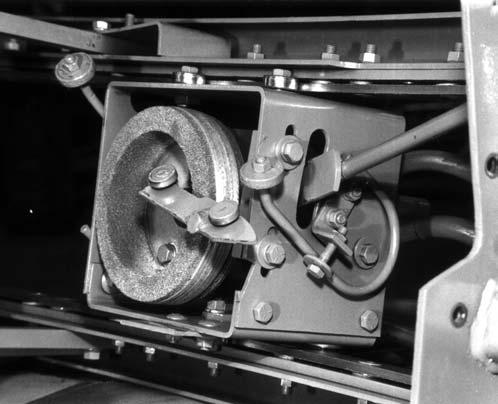
Reburnishing Electric Clutch (Fig. 77)
NOTE: A Reburnishing Tool can be obtained from your local Gehl dealer. In addition, a 37 Tooth Length-of-Cut Sprocket will have to be ordered separately.
Warning
BEFORE proceeding, exercise the MANDATORY SAFETY SHUTDOWN PROCEDURE (page 8).
In the event that the Electric Clutch does NOT provide adequate torque due to having oil or grease on the surface of the Clutch, the proper torque can be restored by carrying-out the following procedure:
1.Shut off the tractor engine and detach the Telescoping PTO Drive.
2.Remove the Clutch Electromagnet and Armature from the Harvester and clean the components with safety solvent.
3.After the components are cleaned, replace them onto the Harvester.
4.Remove the Attachment Driven Sprocket Chain and loosen the Length-of-Cut Drive Chain.

5.Install the 37 Tooth Length-of-Cut Sprocket and install the Clutch Reburnishing Tool. Secure the Tool to the 37 Tooth Sprocket with a 5/16 x 1-3/4 Grade 5 Cap Screw and Hexagon Nut.
6.After reconnecting the Telescoping PTO Drive, run the Harvester at full tractor PTO RPM and engage the Electric Clutch in ’’Reverse’’ for 10 to 12 seconds.
Warning
After slipping the Clutch for 10 to 12 seconds, it will be smoking and very HOT; DO NOT TOUCH THE CLUTCH!
7.Allow the Clutch to cool-off; this should take approximately 1 hour. Do NOT attempt to expedite cooling by using water as this may cause warpage.
8.If the Clutch did NOT smoke when step 6 was carried-out, repeat steps 6 & 7.
9.With the PTO running at a speed as close to idle as possible while still keeping the tractor running when the Clutch Electric is engaged, continue to engage and disengage the Electric Clutch in short bursts until the Grade 5 Cap Screw in the Reburnishing Tool fails.
10.Remove the Reburnishing Tool, install the desired Length-of-Cut Sprocket and reinstall the Attachment Drive Chain.