4 minute read
CHAPTER 10 PREPARING FOR FIELD OPERATION

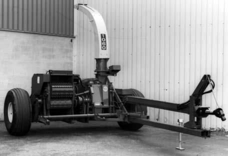
TRACTOR HITCH ALIGNMENT (Figs. 83 & 84)
Position the tractor drawbar hitch hole centerline directly in-line with the tractor PTO Drive Shaft, and secure so as to eliminate any side to side movement of the tractor drawbar. If the tractor drawbar can NOT be positioned in-line, position it toward the left, as close as possible to the centerline of the PTO shaft. It is important to use the 1″ dia. Hitchpin furnished with the Harvester to help center the Harvester Tongue with the tractor drawbar and reduce the amount of side to side movement. Keeping the Tongue in-line and minimizing side to side movement is essential in eliminating drive-line vibration, especially when maneuvering corners.
The front to rear position of the tractor drawbar hitch hole centerline MUST be correct to insure the proper Universal Joint relationship. The tractor drawbar hole should be 16″ (405 mm) from the rear of the 1-3/8 diameter 1000 RPM tractor PTO Shaft, or 20″ (508 mm) from the rear of the 1-3/4 diameter 1000 RPM tractor PTO Shaft.
1 – Tractor Drawbar* (Top View)
2 – Drawbar Pin Hole In-Line or to Left (as close as possible) of PTO Centerline
3 – 1000 RPM Tractor 1-3/8 PTO Shaft*
4 – 16″ (405 mm), 1–3/8″ Diameter PTO Shaft*
5 – 15-3/8″ (428 mm) (Center of Hitchpin to End of Shaft)*
6 – 6 to 12″(150 to 300 mm)*
7 – 13 to 22″ (330 to 560 mm)* (Top of Tongue to Ground)
* Tractor MUST comply with ASAE Standard S203 Fig. 83: 1-3/8 PTO 1000 RPM
1 – Tractor Drawbar* (Top View)
2 – Drawbar Pin Hole In-Line or to Left (as close as possible) of PTO Centerline
3 – 1000 RPM Tractor 1-3/4 PTO Shaft*
4 – 20″ (508 mm) (Center of Hitchpin to End of Shaft)*
5 – 8 to 12″ (203 to 300 mm)*
6 – 13 to 22″ (330 to 560 mm)* (Top of Tongue to Ground)
7 – Tongue Extension
* Tractor MUST comply with ASAE Standard S203
Fig. 84: 1-3/4 PTO 1000 RPM
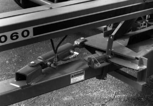
DRAWBAR HITCH CLIPS (Fig. 84)
The Hitch Clips MUST be relocated onto the Tongue Extension to provide a 20″ (508 mm) dimension, between the end of the Splined Drive Shaft and the Hitch Pin Hole in the Clips, to match 1000 RPM 1-3/4 tractor PTO Shaft requirements. This Extension is furnished with the 1-3/4 tractor PTO Telescoping Drive.
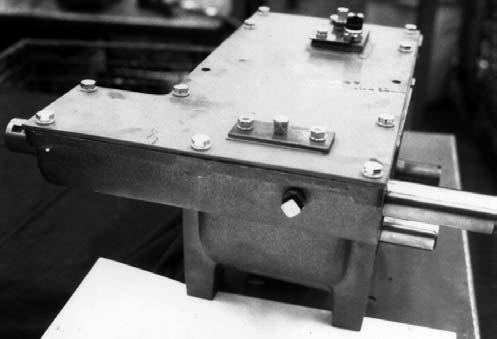
DRIVE LINE ALIGNMENT (Fig. 85)
After the Harvester Hitch Clips and Telescoping Drive are connected to the tractor, the Front Bearing Support should be raised or lowered to place the Fixed-length (Main Drive) and Telescoping Drive Shafts in a straight line (when viewed from the side). The straight-line alignment extends joint life by reducing joint vibrations. To raise or lower Front Bearing Support, temporarily remove the Side Shields on the Front Bearing Stand and remove the (2 each) 3/8 x 5-1/2 Cap Screws and Plain Washers which are securing the Front Bearing Support to the Bearing Support Stand. Next, reposition Bearing Support so that both Shafts are in a straight line. After correct alignment is obtained, line-up the holes in the Bearing Support with appropriate pairs of holes and slots in each side of the Support Stand.
Preparing Harvester
The following points of preparation will have to be made on the Harvester with respect to the Attachment being mounted. Refer to the Adjustments chapter of this manual and, if necessary, the appropriate Attachment Operator’s Manual for specific adjustment details and requirements.
1.Move the Harvester Axles in or out and relocate the Wheel Spindles to match the row spacing and height required for the particular Attachment.
2.Adjust the Attachment Float Spring on the Harvester.
3.Make appropriate Harvester Lift Height and Down–stop Adjustments. Refer to Attachment Positioning topic in the Adjustments chapter.
4.Adjust the Wagon Hitchplate position, if required.
HARVESTER–ATTACHMENT ALIGNMENT (Figs. 86 & 87)
Before proceeding to mount the Attachment, make sure that it is standing on level ground. Also check that the Quick–switch Yokes of the Attachment align vertically with the Quick–switch Pivots on the Harvester. Adjust the Attachment Stands to obtain the right height.
1
2
3
4
5
6
7
* Bearing Height MUST be adjusted for the tractor being used so that the Telescoping Drive and Main Drive Shaft form a straight line.
NOTE: If the Bearing Support holes DO NOT match up when both shafts are in line, move the Support DOWN to the next pair of holes in the Support Stand. After the correct alignment for the Front Bearing is determined, insert and secure the hardware. Then, replace the Side Shields and resecure the attaching hardware.
NOTE: To better enable one man to mount the Attachment, it MUST be squared–up, properly leveled and at the correct height. In addition, the Harvester approach into the Attachment MUST be squarely and directly head–on. BE SURE also to adjust the Attachment Throatsheets to match the Harvester Sidesheet opening.
1.Force the Harvester Lift Arms down to their lowest possible position by inserting the Down Stop Pin (1” Square Bar) into the hole in front of the Cylinder Link and retracting the Lift Cylinder completely. This prevents the Lift Rollers from interfering with the Attachment while it is being mounted.
2.Drive the Harvester into the Attachment and observe that the Attachment Yokes slide over the Harvester Quick–switch Pivots and that the Attachment Throatsheets slide between the Harvester Feed Roll Sidesheets.
3.Connect the Attachment to the Harvester by first forcing a punch into the Quick–switch Pin mounting holes to align them. Then, insert the Quick–switch Pins (from the Tool box) into the holes and secure them with the Hairpin Cotter Pins.
4.Slowly extend the hydraulic Lift Cylinder and remove the Down Stop Pin from above the Lift Cylinder Link.
5.Make the appropriate Attachment positioning adjustments according to the details provided in the Adjustments chapter of this manual.
Caution
BE SURE to exercise the MANDATORY SAFETY SHUTDOWN PROCEDURE (page 8) BEFORE proceeding.
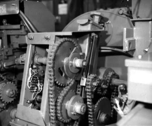
6.Align the Attachment Drive Sprocket with the Attachment Driven Sprocket by adding or removing Washers. After proper alignment is obtained, secure the Drive Sprocket with the Cap Screw, Lock Washer and Special Washer.
NOTE: Operating the Harvester with loosely secured Sprockets can cause excessive Shaft Spline wear.
7.Wrap the Attachment Drive Chain around the Drive and Driven Sprockets. Adjust the Chain length by adding or removing Links, as required. Refer to the Drive Chain Length Table for the necessary Chain length to match the Attachment being mounted.