10 minute read
CHAPTER 9 SERVICE

Caution
BEFORE proceeding to perform all Service routines on this unit, exercise the MANDATORY SAFETY SHUTDOWN PROCEDURE (page 8).
NOTE: The following information is referred to in both the Troubleshooting Guide and the Maintenance Schedule chapters of this manual. It should be understood that all services detailed in this chapter are Owner-Operator responsibilities. Where indicated, certain service routines should only be carried-out under the direction of an authorized GEHL equipment dealer. Furthermore, all Hydraulic Motors, Hoses and Fittings should be routinely checked after every 100 hours of operation for leaks and secure attachment.
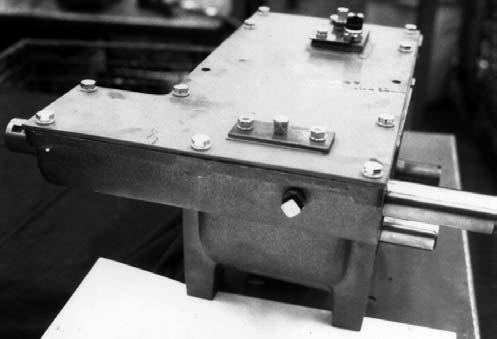
Bevel Gearbox
NOTE: Internal Bevel Gearbox component repairs and replacements should only be attempted by (or under the direction of) an authorized Gehl equipment dealer. The Bevel Gearbox is a mechanism which requires special tools and training to attempt repairs; only your Gehl dealer has the facilities and trained personnel to provide this service.
Blower
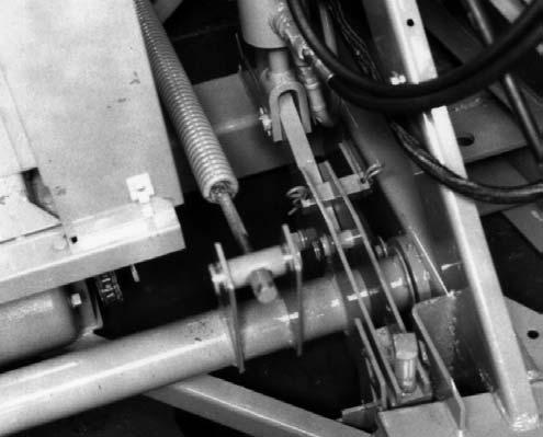
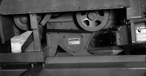
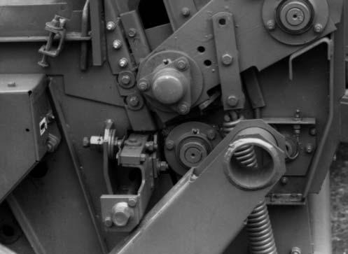
Drive Belt (Fig. 53 & 54)
The Blower Drive Belt should be checked for cracks, tears and evidence of oil after every 50 hours of operation. To remove the Belt, first remove the (6) Bolts which secure the Blower Drive Belt Guard assembly and remove the assembly. Then, lift the Idler, push the slack Belt towards the Blower and, lower the Idler until the Spring is loose. With tension released, slip the Belt off the Drive and Driven Sheaves. If the Belt does NOT clear the Idler Pivot, loosen the (4) bolts at the bottom of the Idler Support and tilt the Support rearward to obtain more clearance. Loosening the (4) bottom Support bolts will NOT disturb the factory set Idler Pulley alignment. Do NOT loosen the (2) top Support bolts. These (2) bolts require adjustment to restore the Idler Pulley alignment.
To install a new Belt, reverse the removal process. Make sure that the new Belt is completely into the Grooves of the Sheaves before restoring Idler tension. After the Belt is replaced and if the Idler Support was removed, BE SURE to replace and tightly secure the (4) Idler Support bolts.
Drive Sheave (Fig. 54)
To remove the Drive Sheave from the Output Shaft of the Bevel Gearbox while the Gearbox is on the machine, remove the Sheave Retaining Bolt from the end of the Shaft and retain all washers, used as spacer shims, for replacement, in the same amount and order, when
Sheave is replaced. The Sheave can NOT be removed from the Shaft without removing the Belt Idler Pivot Stand. When reinstalling the Sheave, place an Internal and External Tooth Lock Washer onto the 1/2 Bolt between the Shaft and heavy Retaining Washer; tighten the 1/2 Bolt with 60 to 70 ft-lb.
Blower Driven Sheave (Fig. 54)
To remove the Blower Driven Sheave from the Harvester, first remove and retain the (6) fasteners which secure the Blower Belt Guard assembly and remove the assembly. Next, release Drive Belt tension and remove the Belt from the Blower Driven Sheave. Then, remove and retain the Bolt and Washer from the end of the Blower Shaft. The Driven Sheave can now be slid-off the Blower Shaft. When reassembling the Sheave onto the Blower Shaft, the Toothed Lock Washer is reinstalled onto the Retaining Bolt between the Blower Shaft and the heavy Retaining Washer. Tighten the Bolt with 60 to 70 ft-lb torque.
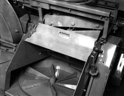
Rim Sheet Wear Liner (Figs. 56 & 57)
The Blower Rim Sheet Wear Liner should be inspected after every 100 hours of operation. The Rim Sheet assembly should always be kept tightly secured to prevent cut forage from wedging between the Rim Sheet grooves and the Blower Sidesheets.
NOTE: If the Blower Fan requires removal for service and/or the Rim Sheet Wear Liner has to be removed and replaced, the following suggested procedure should be carried-out. In addition, do NOT attempt to transport the Harvester without securing the Rim Sheet in place; doing so could result in damage to the Blower Outlet and/or Sidesheets.

Rim Sheet Removal
1.Remove and retain the (6) fasteners which secure the Blower Belt Guard assembly and remove the Guard assembly.
2.Release the Drive Belt Idler tension by lifting the Idler, pushing the slack Belt towards the Blower and lowering the Idler until the Spring is loose. Then, detach the base of the Idler Support by removing the (4) mounting bolts.
3.Remove the three 5/16 Plow Bolts from the bottom of the Outlet at the point where the Rim Sheet assembly is attached to the Outlet.
2 – Wear Liner*
3 – 5/16 x 1 Plow Bolts, Lock Washers & Nuts (3 each)
4 – 5/16 x 3/4 Plow Bolts, Plain Washers, Lock Washers & Nuts (8 each)*
5 – 5/16 x 3/4 Flat Head Socket Cap Screws, Lock Washers & Nuts (3 each)*
6 – Spacer
7 – Removable Rim Shell
4.To loosen the Rim Sheet assembly, a 2 x 4 wooden block MUST be used through the Spinner Chute Inlet hole and the access hole in the rear Sidesheet. While striking against the Rim Sheet assembly with the wooden block, rotate and slide the Rim Sheet down so that the end with the (3) holes can be freed from between the Outlet and the Blower Side Sheets.
NOTE: The block of wood is recommended to help prevent denting a reusable Rim Sheet. If the Rim Sheet is worn out and being replaced, it is NOT necessary to be so careful.
5.After the Rim Sheet is loosened from the base of the Blower Outlet, remove the Jam Nuts and the Take-up Nuts from the Bolts at the top of the Rim Sheet and Blower Outlet.
6.Loosen the top of the Rim Sheet by driving it away from the Blower Outlet. Then, before proceeding, make sure that the entire perimeter of the Rim Sheet is freed from the Blower Sidesheets.
7.Raise the top of the Rim Sheet away from the Blower Sidesheets. Then, pull the Rim Sheet to the rear while rotating it counterclockwise. Continue to pull the Rim Sheet counterclockwise until the 3-hole end of the Rim Sheet clears the right end of Blower Frame.
8.Detach the Wear Liner from the removable Rim Shell.
NOTE: After the Rim Sheet assembly has been removed, clean the outside edges of the front and rear Blower Side Sheets.
Wear Liner Installation & Rim Sheet Assembly Replacement
9.Preassemble the three pieces of the Rim Sheet.
a.Properly position and attach the Removable Rim Shell to the Rim Sheet with the Spacer and (3 each) 5/16 x 3/4 Flat Head Socket Head Cap Screws, Lock Washers and Nuts. Tightly secure the attaching hardware. If removeable Rim Shell is NOT replaced, disregard this step.
b.Properly align and loosely attach the Wear Liner to the Rim Sheet Shell Section with (8 each) 5/16 x 3/4 Plow Bolts, Plain Washers, Lock Washers and Nuts; hardware will be tightly secured after Rim Sheet is in position on Harvester (following step 14.).
c.Clean-out all paint and foreign material from the Rim Sheet grooves. Then, apply a light coating of grease into the grooves around the entire edges of the Rim Sheet assembly.
10.Properly position and install the 3-piece Rim Sheet in somewhat the reverse manner as the original Rim Sheet assembly was removed. Reinstall the Rim Sheet by starting at the area of the Blower Outlet and placing the 3-hole end of the Rim Sheet back against and around the Sidesheets first. Guide the Rim Sheet around the Blower in a clockwise direction.
NOTE: When the Rim Sheet is being installed, it can possibly become hung-up on the material thickness transition point at the base of the Blower Outlet. To facilitate moving the Rim Sheet past this transition; it may be necessary to slide a thin sheet of material past this transition point which can serve as a guide for the end of the Rim Sheet.
11.Guide the end with the (3) holes between the Blower Side Sheets and the Outlet. Using a drift punch, align the holes in the Rim Sheet and Liner with the holes in the Outlet and tightly secure the three parts with (3 each) 5/16 x 1 Plow Bolts, Lock Washers and Nuts.
12.Force the Rim Sheet against the Sidesheets around the entire perimeter of the sidesheets. Insert the flanged-end of the Rim Sheet under the lip of the Blower Outlet.
13.With the Rim Sheet assembly correctly aligned and using a rubber mallet, block of wood or lead hammer, tap along the Side Sheet edges of the Rim Sheet, starting at the Blower Outlet end, to properly seat the Blower Side Sheets into the Rim Sheet grooves.
14.Reinstall the Takeup Bolts and, in an alternating manner, tighten two Nuts while striking against the Rim Sheet Beads to seat the Rim Sheet assembly. Secure the Takeup Nuts with 40 ft-lb (54 Nm) of torque and tighten the Jam Nuts.
15.After the 3-piece Rim Sheet is properly installed and secured, tightly secure the Wear Liner hardware in the manner defined by the drawing (Fig. 57).
16.Rotate the Blower Fan, by hand, to check for interference.
17.Readjust the Fan Paddles following the details in the Adjustment chapter of your manual
18.Reinstall the components removed in steps 1 & 2.
NOTE: After the first 10 hours of operation following Rim Sheet assembly or replacement, the Take-up Nuts torque should be checked and readjusted to 40 ft-lb (54 Nm), as necessary
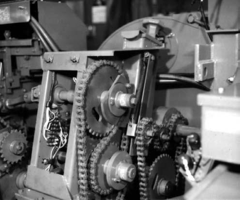
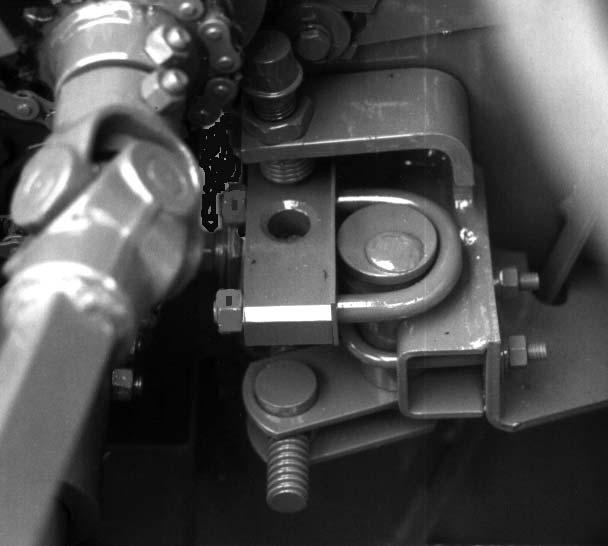
CHAINS & SPROCKETS
Sprocket wear is most often caused by an excessively worn Chain. A Chain which has worn 3% (1.03 times the original length) should be removed and replaced.
This Harvester is designed so that when the Chain Tightener reaches the limit of its adjustment, the Chain has reached a condition of maximum wear. To calculate the original Chain length, multiply the number of Links times 3/4” for a #60 Chain or, times 5/8” for a #50 Chain.
Cutting Mechanism
(Figs. 58, 59, 60 & 61)
Cutterbar
The edge of the reversible Cutterbar (Shear Bar) will remain sharp provided the Knives are kept sharp and the Cutterbar is properly set up to the Knives. When the cutting edge NO longer stays sharp, the Cutterbar can be removed and sharpened or changed (end-for-end) to place a new sharp edge toward the Knives. To remove and replace the Cutterbar, proceed as follows:
Removal
NOTE: Depending on the size of the Tires, Spindle height and position of the Axle Extension, it may be necessary to remove the Wheel or move the Axle Extension out on the right side of the Harvester to obtain clearance for removing the Cutterbar.
1.It may be necessary to remove the trash between the Cutterbar and the Feed Roll Scraper before the Cutterbar can be moved. Using the Remote Adjustment Shaft and the Right Adjustment, move the Cutterbar forward until the rear edge of the Cutterbar is flush with the rear edge of the Cutterbar Support Channel.
2.Remove the Cutterbar Holddown Bolt, Washer and Nut on the right side of the Cutterbar.
3.Do NOT remove, loosen or alter the position of the Cutterbar Hold-down Pin on the left side.
4.Loosen and remove the Lock Nuts, Slot Baffle and Cutterbar Cam U-Bolt on the left side; retain all attaching hardware. BE SURE to use new Lock Nuts when Cutterbar is replaced.
5.Remove and retain the right side (1/2 x 6) Tie Bolt. Do NOT disassemble the Right Side Adjusting Mechanism.
NOTE: In order to remove the Cutterbar, it may be necessary to loosen both pairs of Stem Guide mounting bolts and move the Stem Guides up to free the Cutterbar. After the Guides are moved, retighten the bolts to keep the Guides away while replacing the Cutterbar.
6.From the right side, pull the Cutterbar out from under the left side Cutterbar Hold-down Pin and remove the Cutterbar.
7.Before attempting to replace the Cutterbar or install a new Cutterbar, BE SURE that it is thoroughly cleaned. In addition, clean-off the Cutterbar Support behind the Smooth Feed Roll Scraper. Apply grease or a lubricant to the entire bottom side of the Cutterbar to facilitate sliding it back into its mounting position and to facilitate adjustment.
8.Install the Cutterbar with end bevels facing “up”. Force the left end of the Cutterbar under the Spring-loaded Cutterbar Hold-down Pin on the left side.
9.Do NOT attempt to loosen the left side Hold-down Pin Sleeve. Make sure however, that the Pin is free to slide in its Sleeve.
10.After the Cutterbar is properly aligned, reinstall the right side Tie Bolt and Nut.
11.Apply grease in the Cutterbar Cam groove and reinstall the left side Cutterbar Cam U-Bolt, the Slot Baffle and the Lock Nuts. Torque the Lock Nuts so that the U-Bolt pulls the Cam tightly against the Slot Baffle and Cutterbar.
12.Retighten the right side Hold-down Bolt and Locking Nut.
1
2
3
4
Cylinder Cover (Fig. 62)
The Cylinder Cover Mounting Brackets are secured with the same hardware which attaches the Rear Cylinder Tie Plate to the Sidesheets. If the Tie Plate is removed for access to the Knives (for removal), the Cylinder Cover Mounting Brackets MUST be properly repositioned and secured. When properly attached, the Brackets MUST be secured with their notches on top and facing towards the rear of the Harvester. The proper method to attach and align the Brackets is as follows:

5
6
7
8
9
Refer to the Cutterbar topic in the Adjustments chapter to make the proper Cutterbar adjustments for operation. BE SURE to reset the Stem Guide positions if they had been changed. Set the Stem Guides down against the Cutterbar and make sure that they are clearing the Cutting Cylinder by 1/32 to 1/16″, to prevent damage to the Knives. Then, retighten the Stem Guide Bolts.
NOTE: Loose Stem Guide Mounting Bolts will allow the crop to push the Stem Guides into the Knives and severely damage the Cutting Cylinder.
1.Loosen (but do NOT remove) the Nuts which secure the Brackets to the Rear Cylinder Tie.
2.Force the Cutting Cylinder Cover tightly against the Front Cylinder Tie Plate.
3.Install the Spinner Cover and tighten the Holddown Knobs.
4.Force the Cover Mounting Brackets forward against the Cylinder Rods on both sides of the Cylinder Cover. Then, tighten the (4) Nuts securing the Brackets and Tie Plate.
Knife Replacement (Fig. 63)
After numerous sharpenings, Knives will be grounddown to where the hard-facing has disappeared. In addition, Knives may become deeply gouged or broken and require replacement. To replace a Knife, proceed as follows: