8 minute read
CHAPTER 12 STORAGE

At the end of the harvesting season it is suggested that the following steps be performed:
1.The Electrical Control Box should be stored in a dry place. Install the Dust Caps, where provided, over the ends of the Wire Harness Plug Connectors.
2.Clean the Harvester thoroughly of all dirt, trash, excess grease and any other material that will absorb water and cause rust.
3.Thoroughly lubricate the Harvester as indicated in the Lubrication chapter.
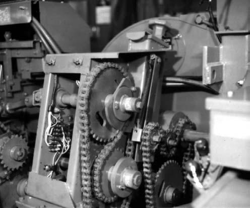
4.Clean and oil all Drive Chains.
5.Paint all the parts from which the paint has been worn to prevent rust.
6.Order and replace any required parts so the Harvester will be ready to operate the next season.
7.Store the Harvester in a dry place where it is neither exposed to weather nor livestock.
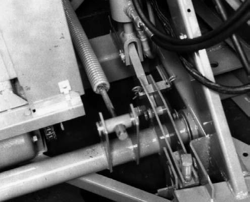
8.Release tension on the Blower Drive Belt if the Harvester is going to be out of operation for a long period of time.
Protection Of Unpainted Surfaces
Apply a rust preventative oil or grease to the following unpainted surfaces:
1.The Front Telescoping Drive Yoke Hub at the PTO drive end.
2.The Front Bevel Gearbox Shaft Splines.
3.All Drive Chains and Sprockets.
4.The Length–of–Cut Sprocket Splined Shaft.
Chapter 13 Troubleshooting
NOTE: This Troubleshooting guide presents problems, causes and suggested remedies beyond the extent of loose, worn or missing parts and it was developed with the understanding that the machine is in otherwise good operating condition. Refer to the index at the back of this manual for Chapter and Topic page references. For additional assistance, BE SURE to contact your local GEHL dealer.
Blower
Problem Cause Remedy
Forage is NOT being blown adequately or Spout is plugging.
Operating too far below rated PTO speed.
Operate the tractor at the proper PTO speed. Check the Spinner Drive Chain to see if it is on the Sprockets. If a Speed Monitor is present: Check that Speed Monitor is plugged-in. Check that all electrical Plugs are connected or, if the Speed Monitor is NOT functioning, have the unit checked per the electrical troubleshooting information provided to the dealer.
PTO is being disengaged before the Harvester is cleaned-out.
Blower Rimsheet and/or Spout is gummed-up.
Disengage PTO only after all forage is cleaned-out.
Remove gum and dirt by either scraping it out or by running very wet forage or freshly cut crop through it; consult with your dealer for information on a Water Tank system.
Blower Paddles are NOT set-out to the Rimsheet. Adjust Paddles; refer to Adjustments chapter.
Blower Belt slipping. Check Belt for wear and/or oil contamination and check for proper Idler alignment.
Spout Liner is worn through. Replace Liner.
Spout Horizontal Extension is interfering. Correct the Extension mounting, as required; refer to the Set-up & Assembly chapter.
Cap is being tipped-down too far. Operate the Cap in a higher position.
Blower Belt is coming off.
PTO is being engaged at too high an RPM. Always engage the PTO at tractor idle.
Blower Fan is obstructed. Check the Fan to see if it turns freely.
Belt Idler is tipped and/or NOT in line. Position Idler perpendicular and in-line with Belt.
Blower Fan Blades are striking Blower Sidesheets.
Locking Collars on Blower Bearings are loose.
Center the Fan and tighten the Bearing Lock Collars.
Blower Arms are bent. Replace Arms. Rimsheet is loose. Tighten Rimsheet Take-up after cleaning and greasing the Rimsheet grooves.
Bolts in Sidesheets are loose. Tighten Bolts.
Cutting Cylinder
Problem Cause Remedy
Crop will NOT feed into Cutting Cylinder.
Knives are too dull.
Upper Rear Feed Roll is packed between the flutes.
Sharpen the Knives and readjust their positions, as required.
Clean-out the fluting.
NO Knife heel relief. Use the Template provided to determine how much to adjust the Knife to Grindstone relationship.
Smooth Feed Roll Scraper is NOT sitting on the Feed Roll.
Clean-out the area between the Roll and the Scraper and lower the Scraper.
Knives wearing-out rapidly.
Soil or sand being picked-up by the mounted Attachment.
Operate the Attachment higher off the ground.
Cutterbar is NOT set-up to Knives. Correct the Cutterbar setting per details in the Adjustments chapter.
All the Knives are NOT at the same radius from center of the Cutting Cylinder.
Material is hairpinning on the Screen (when being used).
Screen is NOT properly set-up to Knives.
Repeat the sharpening process making sure a different Knife is used to start the sequence each time the Sharpener Stone is lowered; see Service chapter.
Readjust Screen following details in Adjustments chapter.
Screen is worn excessively. Remove, rotate or replace Screen.
Knives are worn excessively. Sharpen the Knives and readjust their positions, as required.
Cutting Cylinder diameter is too small and Screen can NOT be properly set-up.
Adjust the Knife positions outward to increase the Cylinder diameter; see Service chapter.
Stems are too long. Knives are NOT sharp. Sharpen the Knives and readjust their positions, as required.
All the Knives are NOT at the same radius from center of the Cutting Cylinder.
Repeat the sharpening process making sure a different Knife is used to start the sequence each time the Sharpener Stone is lowered; see Service chapter.
Cutterbar is NOT sharp. Sharpen, remove and rotate or replace the Cutterbar.
Cutterbar is NOT straight and/or set-up to the Knives.
Check if Cutterbar is straight and correctly set it up to the Knives.
NOT enough material depth in the Feed Rolls to hold stems. Increase the ground speed or windrow size and/or reduce the Length-of-Cut.
Length-of-Cut is too long. Reduce the Length-of–Cut; see Adjustments chapter.
Stem Guides NOT correctly set to the Knives.
Set the Guides from 1/32 to 1/16″ from the cutting edge of the Cutterbar.
CUTTING CYLINDER (continued)
Problem Cause Remedy
Long cobs in silage. Knives are NOT sharp. Sharpen the Knives and readjust their positions, as required.
Knife heel relief is too great. Resharpen the Knives with a Grindstone to Knife heel relationship of 1/32 to 1/16″
All the Knives are NOT at the same radius from center of the Cutting Cylinder.
Repeat the sharpening process making sure a different Knife is used to start the sequence each time the Sharpener Stone is lowered; see Service chapter.
Cutterbar is NOT sharp. Sharpen, remove and rotate or replace the Cutterbar.
Cutterbar is NOT straight and/or set-up to the Knives.
Check if Cutterbar is straight and correctly set it up to the Knives.
NOT enough material depth in the Feed Rolls to hold stems. Increase the ground speed or windrow size and/or reduce the Length-of-Cut.
Tractor RPM is dropping too low. Reduce the ground travel speed to keep the RPM up to the PTO speed.
Knives are striking the Cylinder Sidesheet Tie and/or Cutterbar when Knives are moved-out.
Knives are moved-out too far. Reset the Knives with the Setup Bar.
Cutterbar is NOT moved fully forward. Clean-out the material from in front of the Cutterbar before it is moved forward.
Drive Line
Overrunning Clutch is NOT driving.
Clutch Dogs or Clutch Springs are broken. Replace Dogs and/or Springs; contact your Gehl dealer for assistance.
Clutch Dogs are assembled backwards. Contact your Gehl dealer.
Drive Chains are jumping.
Chain Tension Idler is NOT correctly positioned.
Sprockets or Chains are worn excessively.
Correctly align and/or adjust tension per information in Adjustments chapter.
Lubricate Chains or replace them, as required.
Drive Chains are NOT releasing from Sprocket and are noisy.
Chains are lacking lubrication and/or are worn excessively.
Lubricate Chains or replace them, as required.
Spout
Problem Cause Remedy
Spout turns hard. Spout Flange is dry. Properly grease Spout Flange. Cap moves hard. Cap Pivot Spacers are binding. Oil the Pulleys and Pivot Spacer holes. Forage wedged between Cap and Spout. Remove material buildup.
Spout turns hard with a Horizontal Extension installed.
Cap Gearmotor operate when Spout Control Switch is activated and vice-versa.
Cap Motor or Spout Gearmotor operates slowly.
Spout is tipped in relation to the Blower Outlet. Adjust the Tripod and/or Spout Clamp Bracket to eliminate the binding.
Plugs to the two Gearmotors are reversed. Plug the wires from the Spout Gearmotor into the Main Harness Plug containing wires #6 & #7. Plug the Cap Gearmotor into the Plug containing wires #4 & #7.
Binding in a joint.
Lubricate all joints and check for incorrect joint alignment.
Voltage too low. Check for corrosion in the Plug connections. Clean the Plugs and, if problem is NOT corrected by this, contact your local Gehl dealer.
20 Ampere Circuit Breaker opens when Cap and Spout Switches are operated simultaneously.
Entire electrical control system is dead and does NOT function.
The Control Box is wired such that the Circuit Breaker will trip if the Cap and Spout Switches are operated at the same time.
Circuit Breaker has tripped-out on the Control Box.
Plug-together terminations or wires have separated.
Operate only one Switch at a time.
Reset the main Breaker.
Check the wiring and the Plugs.
FEED ROLLS & ATTACHMENT CONTROLS - ALL HARVESTER MODELS
Feed Rolls will run Forward but NOT in Reverse.
A Plug or wire is loose or corroded. Check wiring and Plug connections; repair as necessary.
The Control Box Toggle Switches are NOT set in their proper positions.
Refer to the procedure for proper Switch operation in the beginning of the Operation chapter. If still NOT working, contact your Gehl dealer.
Reverse Solenoid shifts but the Clutch does NOT engage in the “Reverse” position.
A Plug or wire is loose or corroded. Check wiring and Plug connections; repair as necessary.
Transmission Switch is misadjusted or otherwise malfunctioning.
For Shear Bolt models ONLY, the Reverse Relay on the Harvester is malfunctioning.
Contact your Gehl dealer.
Check Harvester Relay wires for looseness, or incorrect installation. Refer to the Wiring Diagram and reconnect wires properly and securely.
FEED ROLLS & ATTACHMENT CONTROLS - ALL HARVESTER MODELS (continued) PROBLEM CAUSE REMEDY
Electric Clutch does NOT engage when Mode Switch is set to “AUTOmatic” and the Selector Switch is moved to the “Forward” position on Torque Sensor equipped models, or when the Toggle Switch is moved to “FORWARD” on Shear Bolt model.
Circuit Breaker is tripped, a wire is broken, or a Plug or a connection has separated.
Correct wiring and/or reset Breaker. Check all Plugs and connections in the Main Wiring Harness and Clutch wires.
Circuit Breaker does NOT remain set.
Clutch Coil is open.
Have the total circuit checked-out by your dealer.
Keyswitch is “OFF”. Turn on Keyswitch. Open contacts within the Brush Holder.
An improperly low voltage exists at the Electric Clutch.
Have the total circuit checked-out by your dealer.
On Torque Sensor models ONLY, check that the Mode and Selector Switches are properly set. If they are, check that there is NO less than 10-1/2 volts at the Electric Clutch wire Connecting Screw. If the voltage is “0”, set the Toggle Switch to the “MANual” position and check for a voltage reading. If there is a voltage present, then the Selector Switch or the Control Box Relay is malfunctioning. Contact your Gehl dealer.
Proper contact is NOT being made between the Control Box and the tractor battery.
Check that White wire is correctly and properly connected to the battery (–) post and the Red wire is correctly and properly connected to the battery (+) post.
FEED ROLLS & ATTACHMENT CONTROLS - TORQUE SENSOR-PROTECTED MODELS Only
The Torque Sensor does NOT open the Electric Clutch but instead ratchets when overloaded.
The Mode Switch is in the “MANual” position.
Change the Switch setting to “AUTOmatic”.
Wiring to the Torque Sensor contacts is loose or disconnected.
Torque Sensor Switch contacts are set farther than 0.060″ from face of Sprocket.
Torque Sensor Sprocket or Contact Points are coated with a material which does NOT conduct electricity.
Excessive ratcheting has caused a breakdown of the internal components in the Torque Sensor.
Re-secure wire or check Plug connections.
Readjust the contact gap per details in the Adjustments chapter.
Clean the Sprocket and Contact Points with a safety solvent.
Contact dealer for possible Torque Sensor replacement.