CHAPTER 9 SERVICE
CAUTION
bolts. These (2) bolts require adjustment to restore the Idler Pulley alignment.
BEFORE proceeding to perform all Service routines on this unit, exercise the MANDATORY SAFETY SHUTDOWN PROCEDURE (page 8). 1
NOTE:
The following information is referred to in both the Troubleshooting Guide and the Maintenance Schedule chapters of this manual. It should be understood that all services detailed in this chapter are Owner-Operator responsibilities. Where indicated, certain service routines should only be carried-out under the direction of an authorized GEHL equipment dealer. Furthermore, all Hydraulic Motors, Hoses and Fittings should be routinely checked after every 100 hours of operation for leaks and secure attachment.
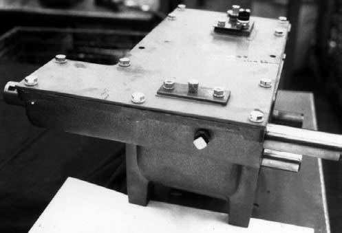
BEVEL GEARBOX NOTE:
Internal Bevel Gearbox component repairs and replacements should only be attempted by (or under the direction of) an authorized Gehl equipment dealer. The Bevel Gearbox is a mechanism which requires special tools and training to attempt repairs; only your Gehl dealer has the facilities and trained personnel to provide this service.
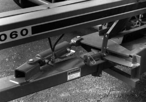
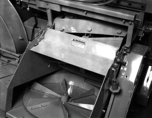
BLOWER
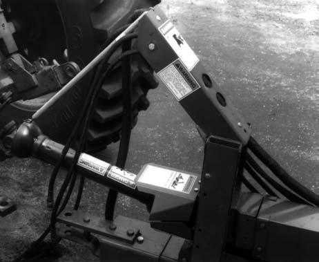
1 – Blower Drive Shield Mounting Bolts (2 of 6)
Fig. 53
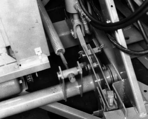
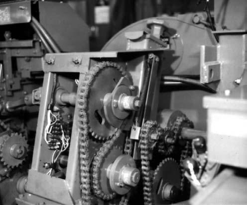
To install a new Belt, reverse the removal process. Make sure that the new Belt is completely into the Grooves of the Sheaves before restoring Idler tension. After the Belt is replaced and if the Idler Support was removed, BE SURE to replace and tightly secure the (4) Idler Support bolts.
3
4
1
6 5
2
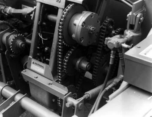
Drive Belt (Fig. 53 & 54) The Blower Drive Belt should be checked for cracks, tears and evidence of oil after every 50 hours of operation. To remove the Belt, first remove the (6) Bolts which secure the Blower Drive Belt Guard assembly and remove the assembly. Then, lift the Idler, push the slack Belt towards the Blower and, lower the Idler until the Spring is loose. With tension released, slip the Belt off the Drive and Driven Sheaves. If the Belt does NOT clear the Idler Pivot, loosen the (4) bolts at the bottom of the Idler Support and tilt the Support rearward to obtain more clearance. Loosening the (4) bottom Support bolts will NOT disturb the factory set Idler Pulley alignment. Do NOT loosen the (2) top Support 58
1 – Blower Drive Sheave 2 – Idler Support 3 – Tension Spring 4 – Belt Idler 5 – Blower Drive Belt 6 – Blower Driven Sheave
Fig. 54
Drive Sheave (Fig. 54) To remove the Drive Sheave from the Output Shaft of the Bevel Gearbox while the Gearbox is on the machine, remove the Sheave Retaining Bolt from the end of the Shaft and retain all washers, used as spacer shims, for replacement, in the same amount and order, when