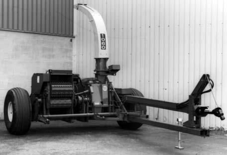
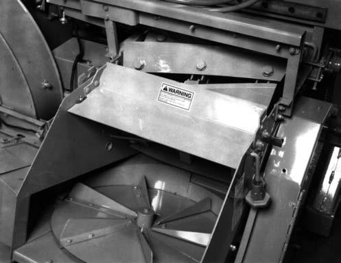
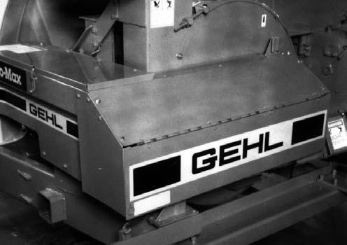
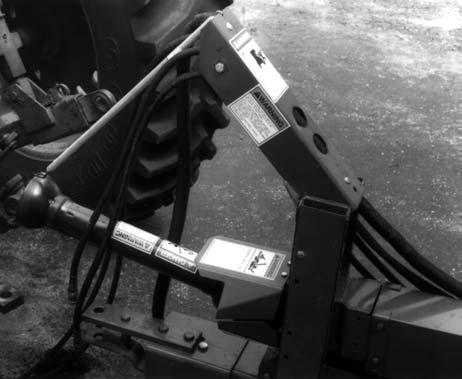
CHAPTER 14 SET-UP & ASSEMBLY The Forage Harvester is shipped in the configuration shown in Fig. 92. The following common component completing parts are NOT attached to the Main unit:
Extension is being installed in the future (anytime after initial set-up), some assembled components will have to be removed and replaced.
NOTE: The following abbreviations are used in these procedures:
Fig. 92: Typical Shipping Configuration
—
Axles, Wheels & Tires
—
Tongue
—
Hitchjack
—
Front Bearing Stand, Main Drive and Guard
—
Telescoping PTO Drive
—
1-3/4 Drive Tongue Extension
Procedures established in this set-up instruction are given in a step-by-step manner, with various parts of the assembly process listed in such a way as to make it possible for one set-up person (with appropriate tools and equipment) to do the sequence without having to remove parts in order to make other component attachments. This chapter is divided into two topics: Common Components and Accessory Components. Accessory Components, such as a Tripod or Horizontal Extensions, are also referenced in the Spout and Controls mounting procedures so as to likewise help to avoid unnecessary removal and replacement steps during initial set-up. It should be understood that, if an additional Vertical Spout Extension or Horizontal Spout
102
CB
-
Carriage Bolt
CS
-
Cap Screw (Hexagon Head)
RHMS
-
Round Head Machine Screw
SHSS
-
Socket Head Set Screw
THMS
-
Truss Head Machine Screw
N
-
Nut (Hexagon)
LN
-
Lock Nut (Hexagon)
HMN
-
Hexagon Machine Nut
WN
-
Wing Nut
L
-
Lock (Washer)
P
-
Plain (Washer)
NF
-
National Fine (Thread)
Unless otherwise noted, the standard fastening procedure is to secure two parts with a CS, L and N. A part with a mounting slot should be secured with a P against the slotted surface. Attaching hardware, which will require installation in the path of the cut crop, should always be installed with the head of the screw on the same side of the part which will be in contact with the material.
NOTE: Before proceeding, remove all components which are attached or banded to the Harvester Frame or otherwise included in the Toolbox. Shear Bolts should also be taken out of the Toolbox and placed in appropriate Shear Bolt Holders, where provided. As shown in Fig. 92, The Spout and Cap assembly is shipped attached to the Harvester Frame and MUST be removed before proceeding to setup the unit..