Belarus 1822.3 1822B.3 2022.3 2022B.3 Operator's Manual - PDF DOWNLOAD

Page 90

2022.3-0000010 OM

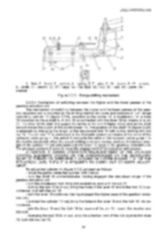
1 – fork, 2 – hood, 3 – sphere, 4 – spring, 5, 7 – pins, 6, 10 – levers, 8, 12 – covers, 9 – shaft, 11 – sector, 13, 17 – keys, 14 – ball lock, 15 – nut, 16 – bolt, 18 – case; 19 – bracket. Figure 3.3.5 – Range shifting mechanism 3.3.3.4 Mechanism of switching between the higher and the lower passes of the gearbox reduction unit The mechanism of switching between the higher and the lower passes of the gearbox reduction unit is mounted on the shifting mechanism cover and consists of “L-H” range controlling cylinder 11 (figure 3.3.6), mounted on the center 10, a double-end 14, a lever 18 mounted on the a shaft 5. A fork 16 is connected with the lever 18 by means of a pin 17. The lever of the shaft 5 engages the carrier of the fork 3 (figure 3.3.2) and as the shaft turns it moves the clutch of the synchronizer 14. The position of the shaft 18 (figure 3.3.6) is adjusted by changing the length of the double-end bolt 14 with further locking with the nut 13. The cylinder 11 is connected to the hydraulic system by means of the valve of the hydraulic valve group 7. The switch 6 connects the valve of the hydraulic valve group 7 to the electric circuit only when the speed shifting lever is in neutral position. A retracted position of the cylinder 11 rod corresponds to the lower “L” pass of the gearbox reduction unit. The pressure sensors 8 serve to index the engagement of the reduction unit passes. ATTENTION: IF DURING OPERATION MALADJUSTMENT OF THE CYLINDER CONTROL ELEMENTS OCCURS OR THE SYNCHRONIZER ON THE SECONDARY SHAFT IS TURNED ON IMPROPERLY (HIGHER OR LOWER PASSES “L-H” OF THE REDUCTION UNIT), THEN IT IS REQUIRED TO CARRY OUT CYLINDER ADJUSTMENT! To adjust the cylinder 11 (figure 3.3.6) proceed as follows: - move the piston inside the cylinder until it stops. - turn the shaft 18 contraclockwise, having engaged the step-down range of the gearbox reduction unit; - turn the double-end bolt 14 by 8-9 revolutions, lock with the nut 13; - turning the fork 16 in or out, bring the holes in the lever 18 and in the fork 16 in coincidence, lock with the nut 15; - turn the lever 18 clockwise, having engaged the higher pass of the gearbox reduction unit; - protract the cylinder 11 rod, bring the holes in the lever 18 and the fork 16 into coincidence. - join the lever 18 and the fork 16 by means of the pin 17, mount the washer and forelock; - screwing the bolt 20 in or out, stop the spherical part of the bolt against the lever 18, lock with the nut 19. 89


Turn static files into dynamic content formats.

Create a flipbook

Articles inside

10. TRACTOR DISPOSAL

1min
page 352

8.8 Safety requirements for preservation

1min
page 350

8.5 Preservation

2min
page 348

troubleshooting

4min
pages 344-346

washer, acoustic alarm

2min
page 336

7.15.3 Search and elimination of failures in engine start-up system

4min
pages 332-333

7.15.5 Search and elimination of failures in air conditioner electrics

3min
page 335

7.15.4 Search and elimination of failures in lighting facilities

3min
page 334

7.14.3 Section R-23LS lowering valve disassembly procedure

1min
page 329

troubleshooting

8min
pages 321-326

7.11 Possible failures of FDA and guidelines for troubleshooting

8min
pages 315-320

troubleshooting

1min
page 314

7.9 Possible failures in pneumatic system and guidelines for troubleshooting

3min
pages 312-313

7.8 Possible failures of brakes and guidelines for troubleshooting

5min
pages 309-311

7.7 Possible failures in front power take-off shaft and guidelines for troubleshooting

1min
page 308

troubleshooting

3min
pages 305-306

3.13 Undercarriage and tractor wheels

1min
page 129

3.12.3 Front PTO control

1min
page 128

3.12.2 FDA drive control

1min
page 127

3.11.4.2 Adjustment of FDA drive automatic switch

2min
page 125

3.11.3 Wheel gear group

2min
pages 122-123

3.9.5 Check and adjustment of pneumatic system pressure regulator

1min
page 118

system

1min
page 117

3.9.3 Double-line pneumatic drive of trailer brakes

2min
page 113

3.8.6 Parking brake

2min
page 110

3.8.7 Parking brake adjustment

1min
page 111

3.8.5 Service brake adjustment of “BELARUS-1822 .3/2022 .3”

1min
page 109

3.8.4 Service brake control of “BELARUS-1822 .3/2022 .3”

3min
pages 107-108

3.7 Front power takeoff shaft

3min
pages 101-102

3.8.3 Service brake adjustment of “BELARUS-1822.3/2022.3”

4min
pages 105-106

3.8.2 Service brake control of “BELARUS-1822.3/2022.3”

1min
page 104

3.6.2 Rear PTO control

2min
page 100

3.5.6 Rear axle final drive adjustment

2min
page 96

3.4 Reduction unit electro-hydraulic control

2min
pages 92-93

reduction unit

2min
page 90

3.3.3.5 Gearbox control

1min
page 91

3.1.4 Engine cooling system

1min
page 75

3.1.2 System of engine air cleaning

4min
pages 72-73

3.2.4.3 Clutch check for purity of disengagement

2min
page 82

3.1.3 System of charged air cooling

1min
page 74

3.3.3.3 Range shifting mechanism

1min
page 89

3.2.5 Clutch case

2min
page 83

3.1.1.2 Engine elements

8min
pages 68-71

2.24 Fuel tank valve control

1min
page 66

2.19.3 BELARUS seat installation for operation on reverse

1min
page 60

2.18.4 Cab hatch opening

1min
page 58

2.23 Reverse post controls of BELARUS-1822 .3/2022 .3

2min
pages 64-65

2.17.2 Fuses for electrical equipment system

3min
pages 53-55

2.17.3 Fuses of electronic control systems

1min
page 56

2.19.4 “Grammer” seat adjustments

1min
page 61
Issuu converts static files into: digital portfolios, online yearbooks, online catalogs, digital photo albums and more. Sign up and create your flipbook.