3 minute read
3.8.4 Service brake control of “BELARUS-1822 .3/2022 .3”


- check the full travel of unlatched pedals under a force of (300±30) N applied. It shall be within 100…120 mm. If the full travel of the pedals falls outside these limits, readjust them proceeding as follows: ) turn out the locknut 2 (figure 3.8.4) on cylinder rod by several turns; b) turning rod 1 of working cylinder, adjust cylinder length and pin stroke of the working cylinder fork within the necessary limits; c) tighten the locknut 2.
1, 2 – main cylinder; 3, 4 – tank; 5, 6 – pedal. Figure 3.8.5 – Bleeding of brakes and adjustment of full pedal travel
5) Check the efficiency of the service brakes when the tractor moves on a dry hardsurface road with the clutch disengaged. When pressing the interconnected brake pedals with force of 590…600N the stopping distance shall not exceed 6.4 m at tractor speed of 20 km/h. Unstraightness of tractor movement during braking shall not exceed 0.5 m. If necessary, adjust simultaneity of breaking beginning, using the length of one of the break working cylinders, as indicated above.
3.8.4 Service brake control of “BELARUS-1822 .3/2022 .3”
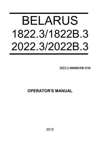
The service brake control scheme of “BELARUS-1822 .3/2022 .3” is shown in figure 3.8.6. The brakes control is intended for force transfer when braking on forward travel an on reverse from actuating devices (pedals) to executing mechanisms (brake working cylinders) by means of brake fluid supply. The type of brake actuator is hydrostatic with suspended pedals. The brake control of “BELARUS-1822 .3/2022 .3” consists of main cylinders 1, 7 (for forward travel) and 3 (for reverse), of suspended pedals 5, 6 (for forward travel) and 2 (for reverse), of valves 10, 12 (for automatic switch from tractor operation on forward travel to operation on reverse and vice versa), of brake working cylinders 16, 18, of levers 15, 17, of flexible hoses 14, of pipelines 8, 9 (for forward travel) and 4, 11, 13 (for reverse). In the mode of forward travel when pressing the pedal 5, 6 the brake fluid comes from the main cylinders 1, 7 through the pipelines 8, 9 to the valves 10, 12. In the valves the pistons move to the extreme position and shut inlets of the pipelines 11, 13. Then the brake fluid is fed to the working cylinders 16, 18 through the flexible hoses 14 and moves the pistons which work on the levers 15, 17 through the rods. The levers turns and work on the brakes through the shafts. In the reverse operation mode when pressing the pedal 2 the brake fluid comes from the main cylinders 3 through the pipelines 4, 11, 13 to the valves 10, 12. In the valves the pistons move in the opposite directions and shut inlets of the pipelines 8, 9. Then the brake fluid is fed to the working cylinders 16, 18 through the flexible hoses 14, performing actions similar the described above.
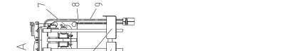

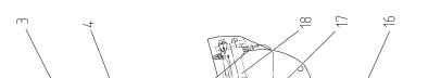


1 – left master brake cylinder; 2 – brake pedal for reverse; 3 – master brake cylinder for reverse; 4, 8, 9, 11, 13 - pipeline; 5 – left brake pedal; 6 – right brake pedal; 7 –right master brake cylinder; 10, 12 – valve 14 – flexible hose; 15 – left brake lever; 16 – left working brake cylinder; 17 – right brake lever; 18 – right working brake cylinder. Figure 3.8.2 – Service brake control diagram of “BELARUS-1822
.3” .3/2022