3 minute read
troubleshooting


Oil leakage through the cups Disconnect the tractor in order to detach from clutch coupling case and replace cups
7.4 Possible failures in the electronic control system for rear axle differential lock, front driving axle drive, front power take off shaft, GB reduction gear and instructions for their troubleshooting
The list of possible failures in the electronic system for rear axle DL, FDA drive, FPTO (if mounted), GB reduction gear (if mounted) and instructions for their troubleshooting are shown in Table 7.4. Table 7.4
Failure, external manifestation, cause Troubleshooting
FDA drive or rear axle DL can not be engaged in the forced mode, or GB reduction unit can not be shifted to the higher pass, FPTO drive can not be engaged
Power supply voltage is not transferred to the respective distribution valve solenoid Check according to the electric circuit diagram (Annex ) if the power supply voltage is transferred to the respective distribution valve solenoid
Jamming of the respective distribution valve spool Rinse the distribution valve
None of the drives (FDA, rear axle DL, FPTO) can be engaged and GB reduction unit can not be shifted to the high gear
There is no pressure in the transmission hydraulic system Eliminate the failure in the transmission hydraulic system
When the front PTO drive is engaged, indicating lamp lights up but the PTO shaft end extension fails to rotate
Make sure that the cylinder pin is moving while engagement If the cylinder rod is moving, FPTO shaft electric control is operating in a proper manner
Check the adjustment of FPTO brake band tightening Adjust if necessary
Rear axle DL can not be engaged in an automated mode when guide wheels are in the forward motion position
Big clearance between the bracket and the butt end of left or correspondingly right sensors 3 of guide wheels turning angle Adjust the clearance within 3±0,2 mm by rotating nuts 6 and 7 as shown in figure 7.4.1
Breakage in the electric “minus” circuit of power supply or in the
“signal” circuit of left or correspondingly right sensor of turning angle Check electric circuits according to the electric connections diagram (Annex ).
Left or correspondingly, right sensor of turning angle is faulty Replace faulty sensor
Rear axle DL or FDA drive is constantly activated in the automatic mode (fail to get deactivated while guide wheels turning)
Breakage in the “plus” circuit of power supply of left or correspondingly right sensor of turning angle Check “plus” circuit of sensor power supply according to the electric connections diagram (Annex )
While tractor slowing down (depressing both brake pedals simultaneously),
FDA drive can not be engaged and rear axle DL can not be disengaged (depressing either of the brake pedals)
Faulty one or both brake actuation sensors 12-21 (actuation of brake pedals) Simulate sensor actuation one-by-one by means of contact closure in cable sockets to the sensors. Replace the faulty sensor
Cable of connection to sensors Check the cable for operability according to the
12-21 is faulty Faulty relay in FDA drive actuation circuit and rear axle DL deactivation circuit while slowing down electric circuit diagram (Annex A) Replace the relay
Table 7.4 finished Failure, external manifestations, cause
Troubleshooting
After engine start-up, indicator of the reducing unit first gear engagement does not light up, or after reducing unit top gear is engaged indicator of the reducing unit top gear engagement does not light up
Oil pressure in pilot hydraulic system is below 0.8 MPa Check oil pressure value according to oil pressure indicator in transmission, located on gauge board. Correct hydraulic system failure or make adjustment of hydraulic relief valve
Faulty pressure sensor “ ” of GB reducing unit first or top gear accordingly, or burned-out lamp indicating GB reducing unit engagement, or burned-out GB reducing unit led lamp. Replace faulty components (pressure sensor or indicating lamp or led lamp)
Opening of circuit leading from sensor to indicating lamp or opening of circuit from sensor to led lamp Check according to the electric circuit diagram (Annex B) operability of circuit “sensor – indicating lamp” or “sensor – led lamp” and correct opening in faulty circuit
FDA drive is permanently engaged in any of three positions of the switch
The FDA drive control valve spool was blocked abroach Rinse the FDA drive control valve
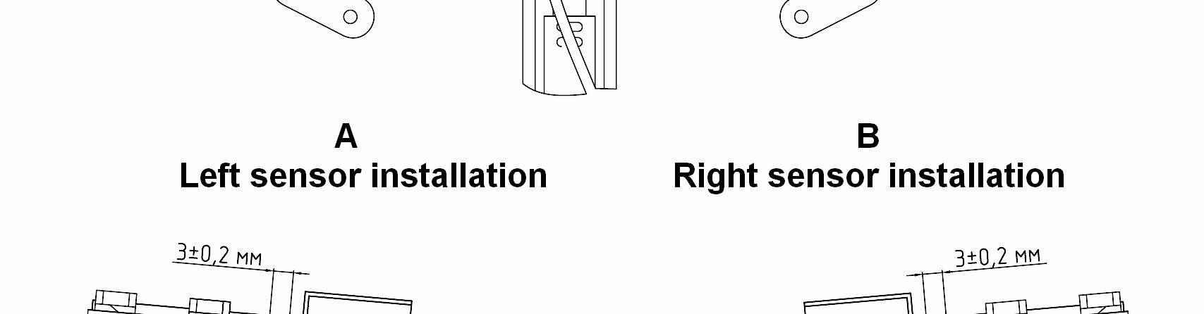

1, 3, 4 – brackets; 2 – angular position sensor (±13°, DL); 5 – angular position sensor (±25°, FDA); 6 – outer nut; 7 – inner nut; 8 – front axle (top view). Figure 7.4.1 – Directive wheels angular position sensors 3 adjustment