1 minute read
3.12.3 Front PTO control


The system is powered from the tractor on-board electrical circuit through the fuse block 4. The FDA drive control system gets powered after the engine has been started. The switch 2 has three positions: - “FDA automatic control” (upper fixed position); - “FDA engaged positively” (lower fixed position); - “FDA off” (middle fixed position). In position of the switch 2 “FDA off” the FDA drive clutch is connected with drain and FDA drive is off. In position of the switch 2 “FDA automatic control” the FDA drive is automatically engaged as the tractor moves forward by the sensor 6, sending enabling signal, depending on the rear wheel skidding. Herewith, oil flow is supplied under pressure to the FDA drive engaging clutch. The FDA drive is disabled automatically when the front wheels are turned to the angle of more than 25° to any direction from the straight line position. As the tractor reverses and the FDA is controlled automatically, the FDA drive always disengages. When the switch 2 is set into position “FDA engaged positively” the FDA drive is forcedly engaged at forward motion as well as at reverse irrespective of the front wheel turning angle and skidding. ATTENTION: PRESSING THE INTERCONNECTED BRAKE PEDALS ENGAGES THE FDA DRIVE IRRESPECTIVE OF THE SWITCH 2 POSITION! ATTENTION: DRIVING ON ROADS WITH HARD SURFACE THE FDA SHALL BE DISENGAGED TO AVOID INCREASED WEAR OF FRONT TYRES AND PARTS OF THE DRIVE! ATTENTION: IT IS FORBIDDEN TO ENGAGE THE FDA POSITIVELY WHEN TRACTOR SPEED EXCEEDS 13 KM/H!
3.12.3 Front PTO control
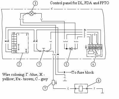
The FPTO is mounted on “BELARUS - 2022.3/2022 .3” tractor against order. Elements of the electrical part of FPTO control are introduced in subsection 2.14 “Control panel for rear axle DL, FDA and FPTO drives. Rear power takeoff control.” An electric circuit diagram of the FPTO control system is introduced in figure 3.12.3. Elements of the hydraulic part of FPTO control are introduced in subsection 3.7 “Front power takeoff shaft”.
1 – FPTO switch; 2 – two-position FPTO switch; 3 – FPTO “on” annunciator; 4 – relay; 5 – diode; 6 – electromagnet of FPTO valve group; 7 – junction block. Figure 3.12.3 – Electric circuit diagram of the FPTO control system