3 minute read
2.17.2 Fuses for electrical equipment system


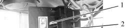
2.17.2 Fuses for electrical equipment system To get access to cutout fuses located in the upper compartment of the cab on the right do a screw 2 out (figure 2.17.1) and remove a cover 3.
1 – deflectors, 2 – screw; 3 – cover, 4 – upper shield unit of button switches. Figure 2.17.1 – Access to cutout fuses located in the upper compartment of the cab The fuses located in the upper compartment of the cab are shown in fig. 2.17.2.
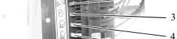
1 – 15A cutout for rear lights (a pair of inner lights); 2 – 7.5A cutout for cab light and “road-train” light (if available); 3 – 7.5A cutout for rear screen washer and wiper; 4 – 15A cutout for front working lights (on the roof); 5 – 25A cutout for rear working lights (a pair of outer lights); 6 – 25A cutout for air conditioner control system;. Figure 2.17.2 – Cutouts, located in the upper compartment of the cab To get access to cutout fuses located under the dashboard, do a screw 2 out (figure 2.17.3) and remove a cover 3.
1 – clutch pedal; 2 – screw; 3 – panel Figure 2.17.3 – Access to cutout fuses located under the dashboard

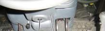

line. The cutout fuses located under the dashboard are shown in figure 2.17.4.

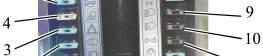
1 – 15A cutout for brake lights; 2 – 15A cutout for front screen washer and wiper; 3 – 15A cutout for warning alarm; 4 – 25A cutout for portable lamp; 5 – 15A cutout for horn; 6 – 25A cutout for road light upper beam; 7 – 7.5A cutout for left marker lights; 8 – 15A cutout for right marker lights and for dashboard illumination; 9 – 7.5A cutout for lower beam of left road light; 10 – 7.5A cutout for lower beam of right road light; 11 – 7.5A cutout for flasher relay; 12 – 15A cutout for power supply circuit of instruments and reduction unit control
Figure 2.17.4 – Cutouts located under the dashboard
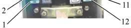
To get access to cutout fuses, located under on the facing frame, do a screw 2 (figure 2.17.5) out and remove a cover 3.


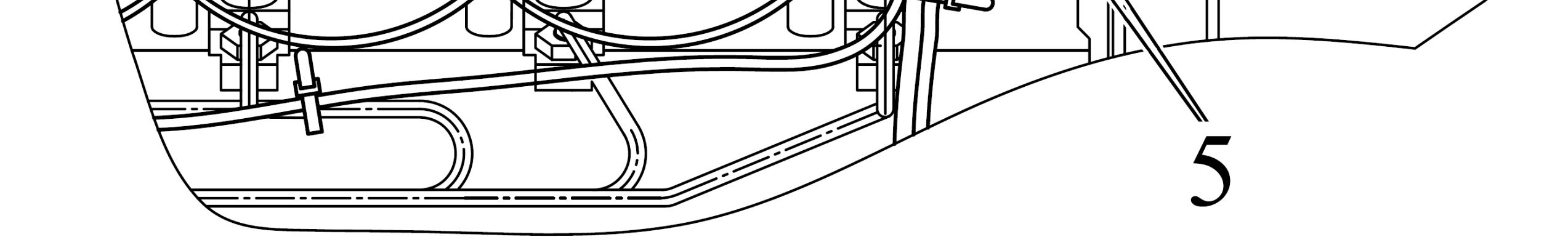
1 – engine, 2 – screw; 3 – cover; 4 – facing frame; 5 – 25A cutouts for heating plugs Figure 2.17.5 – Access to cutout fuses, located on the facing frame
The cutouts, located on the facing frame, are shown in figure 2.17.6.
1 – 30A cutout for front working lights on the handgrips and for power supply to electrical equipment components, powered when the starter and instrument switch is set to position “instruments on”; 2 – 7.5A cutout for vale of fuel fortifier; 3 – 30A cutout for power supply to electronic systems of DL, FDA, FPTO and RLL; 4 – 80A cutout for power supply to electrical equipment components, located on the cab roof; 5 – 60A cutout for power supply to electrical equipment components, powered when the starter and instrument switch is set to position “off” Figure 2.17.6 – Cutout fuses located on the facing frame
The cutout for the voltage converter (VC) 2 (figure 2.17.7) is built into the voltage converter housing.
1 – voltage converter; 2 – 20A cutout for voltage converter. Figure 2.17.7 – Assembly of voltage converter with cutout The installation place for the voltage converter is shown in figure 3.17.8.
1 – voltage converter; 2 – battery manual disconnect switch; 3 – battery. Figure 2.17.8 – Voltage converter assembly