2 minute read
3.5.6 Rear axle final drive adjustment


3.5.6 Rear axle final drive adjustment
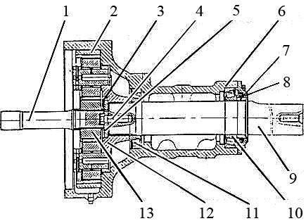
If it is required to replace the parts and assembly units of the final drives carry out the further assembly and adjusting operations in the following order: - press the inner ring of the outer bearing 10 on the axle shaft 9 (figure 3.5.2), having previously heated it in oil, until it stops against the bushing 7; - press the outer rings of the bearings 10, 11 in the tube 6 until they stop against the tube collar; - mount the axle shaft assembled with the inner ring of the outer bearing into the tube and fit the inner ring of the inner bearing 11 on the axle shaft; - fit the carrier assembly 12 on the axle shaft splines, mount the washer 5 without the shim pack and tighten the bolt 4 with a torque 500 to 550 N·m, release the bolt and tighten it again manually. - measure a distance from the axle shaft end to the outer surface of the washer 5 through its hole using a caliper; - deduct the washer thickness (12 mm) from the measured value and find out the clearance value between the washer and the axle shaft end; - untighten the bolt 4, remove the washer and fill the clearance with the shim pack. Mount the washer and tighten the bolt with a torque 500 to 550 N·m; - check the axle shaft turning torque. It shall make 16 to 21 N·m. If it exceeds the limits specified above, increase the shim pack and vice versa. The adjustment shall be carried out before mounting the crown wheel 2 and the cover 8 with sealing. - lock the bolt with the lock plate 3, having previously lubricated the plate surface, joining the washer with grease Lithol-24. The plate nibs shall enter the notches of the carrier 12. If necessary turn the bolt more to make the nib and the notch coincide. IT IS NOT PERMITTED TO UNTIGHTEN THE BOLT! - mount the crown wheel 2. - mount the sun gear 13 assembled with the shaft 1 into the planetary drive carrier and check the drive assembly for easiness of rotation. - mount the cover 8 assembled with the seal, having previously lubricated the seal and the rubber ring with grease Lithol-24. Tighten the bolt attaching the cover. The tapered bearings 10 and 11 shall be adjusted to have a clearance of 0,01 to 0,1
mm.
1 – shaft; 2 – crown wheel; 3 – lock plate; 4 – bolt; 5 – washer; 6 – tube; 7 –bushing; 8 – cover; 9 – axle shaft; 10 – bearing; 11 – bearing; 12 – carrier; 13 – sun gear.
Figure 3.5.2 – Rear axle final drive adjustments