8 minute read
3.1.1.2 Engine elements


3.1.1.2 Engine elements
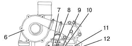
The location of main engine elements is shown in figures 3.1.1 and 3.1.2. The diagram of the engine lubricating system is shown in figure 3.1.3.
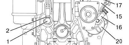
1 – oil crankcase; 2 – oil pump; 3 – torque vibration damper; 4 – crankshaft pulley; 5 – fan drive belt; 6 – timing gear cover; 7 – tensioning pulley; 8 – alternator drive belt; 9 –fan; 10 – water pump; 11 – thermostatic regulator housing; 12 – piston pin; 1 – connector rod, 14 – piston; 15 – sleeve; 16 – cover cap (2 pieces); 17 – covers for cylinder heads; 18 – cylinder head (2 pieces.), 19 – cylinder head gasket; 20 – cylinder block; 21 – back plate; 22 – flywheel; 23 – counterweight; 24 – cover; 25 – crankshaft; 26 – piston cooling nozzle; 27 – oil receiver.
Figure 3.1.1 – Engine in section Cylinder block 20 (figure 3.1.1) is the main engine case-shaped part and is made as a monoblock and is represented as a rigid cast-iron casting. There are six dismountable sleeves 15 installed in the cylinder block bores. Cooling liquid circulates between cylinder block walls 20 and sleeves 15. Cylinder block has a lengthway oil passage from which oil through cross passages is supplied to crankshaft 25 main bearings, and then to cam shaft 1 bearing journals (figure 3.1.2) and nozzles 26 (figure 3.1.1) for cooling down pistons 14. Nozzles for cooling down pistons are mounted in the cylinder block in the upper part of the second, fourth and sixth crankshaft supports. There is a platform on the cylinder block water-distribution passage for mounting a fluid-oil heat-exchanger. Oil supply and oil offtake from the heat-exchanger are carried out through passages in the block. Cylinder block 20 is covered with oil crankcase 1 from below.


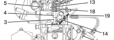

1 – cam shaft; 2 – pusher; – valve; 4 – guide bushing; 5 – wading rod; – turbocharger; 7 – rocking arm; 8 – rocking arm axle; 9 – disk; 10 – dowels; 11 – inner spring; 12 – outer spring; 13 – rack; 14 – nozzle; 15 – fuel pump; 16 – pump for manual fuel supply; 17 – plug for fuel pump head deaerating; 18 – sealing cup; 19 – heating plug; 20 – starter. Figure 3.1.2 – Engine, front view
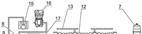
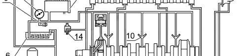
Cylinder heads 18 (figure 3.1.1) (one head for three cylinders) are interchangeable. There are inlet and outlet passages in inner cavities of cylinder heads which are covered with valves 3 (figure 3.1.2). To provide heat output, cylinder heads have inner cavities where cooling liquid circulates. Valve seats are inserted into cylinder heads. Nozzles 14 (3 for each cylinder head), racks 13, rocking arms axles 8 with rocking arms 7, covers for cylinder heads 17 (figure 3.1.1) and cover caps 16 which cover the valve mechanism are mounted onto cylinder heads. There are three heating plugs (figure 3.1.2) installed at each cylinder head on the left. Gasket 19 is mounted between cylinder heads 18 (figure 3.1.1) and cylinder block 20 for the connection thickening. The main parts of the crank-and-rod mechanism are crankshaft 25 with main and connecting-rod bearings, flywheel 22, pistons 14 with piston rings and pins 12, connecting rods 13. Drive gear of valve timing gear (crankshaft gear) and drive gear of oil pump, drive pulley of oil pump, alternator, air conditioner compressor are mounted with force on the crankshaft front end. To reduce the level of the crankshaft torque vibrations, torque vibration damper 3 is mounted on the pulley hub. Piston 14 is made of aluminum alloy. A combustion chamber is installed in the piston-head. In the upper part of the piston there are three furrows – compression rings are mounted into the first two furrows, and an oil-scraper ring with an expander is mounted into the third furrow. Piston pin 12 is hollow, axial movement of the pin in the piston pin boss is limited by locking rings. Connecting rod 13is steel of I section. A bushing is pressed into the connecting rod upper head. In the upper head of the connecting rod and the bushing there is a hole to provide piston pin lubrication. Flywheel 22 is fixed to the crankshaft flange by means of bolts. A steel toothed rim is pressed onto the flywheel. Valve timing gear consists of gears, cam shaft 1 (figure 3.1.2), inlet and outlet valves and parts for their mounting and drive of pushers 2, wading rods 5, rocking arms 7, adjusting screws with nuts, disks 9, dowels 10, springs 11 and 12, racks 13 and rocking arms axles 8. A cam shaft is four-support, gets rotation from the crankshaft through timing gears located under cover 6 (figure 3.1.1). Valve timing gear jaw members are made with a slight taper due to which pushers perform circular movements during the operation process. The engine lubricating system is combined: some parts are lubricated under pressure, some – by spattering. Bearings of the cam and crankshafts, the idle gear bushing, rocking arms bushings, crankshaft rod bearings of the pneumatic compressor, the turbocharger shaft bearing are lubricated under pressure from oil pump. Sleeves, pistons, piston pins, wading rods, pushers, the cam shaft jaw members and the fuel pump parts are lubricated by spattering. The lubricating system consists of oil pump of gear type 3 (figure 3.1.3), oil filter with paper filter cartridge 4, centrifugal oil filter 7, fluid-oil heat exchanger 6. There is overflow valve 5 in the oil pump adjusted for pressure from 0.7 to 0.75 MPa. If the pressure increases above the specified value, oil bleeds off from the decreasing space to the increasing space. The adjustment is carried out at the stand by means of adjusting washers. The oil pump through oil receiver 2 takes oil from oil crankcase 1 and through passages in the cylinder block supplies it to the full-flow oil filter with a paper filter cartridge, and the part of oil – to the centrifugal oil filter for cleaning and succeeding discharge to the oil crankcase. Non-adjustable safety valve 18 is built into filter 4 housing. It is intended for maintaining oil pressure in the main oil passage from 0.28 to 0.45 MPa. In case oil pressure exceeds 0.45 MPa, the safety valve opens and excess oil drains to the engine crankcase through the safety valve. Oil cleaned in oil filter 4 is supplied to the fluid-oil heat-exchanger which is built in the engine cylinder block. An oil filter cartridge has overflow valve 20. In case of paper filter cartridge excessive clogging or while starting the engine with cold oil when filter cartridge resistance increases over 0.13 to 0.17 MPa, the overflow valve opens and oil is supplied to the oil passage without entering filter paper. The overflow valve is non-adjustable.
Cooled oil is supplied from the fluid-oil heat-exchanger through passages in the cylinder block to the main oil passage from which it is supplied through passages in the cylin
der block to all engine units and parts which require lubrication in accordance with the diagram of the engine lubricating system in figure 3.1.3. Oil is supplied to turbocharger 15 bearing unit through the tube which is connected at the output of the oil filter with paper filter cartridge.
1 – oil crankcase; 2 – oil receiver; 3 – oil pump; 4 – paper oil filter; 5 – overflow valve; 6 – fluid-oil heat-exchanger; 7 – centrifugal oil filter; 8 – oil pressure indicator; 9 –sensor of oil emergency pressure; 10 – nozzles for cooling down pistons; 11 – crankshaft; 12 – cam shaft; 13 – oil passage of rocking arms axles; 14 – idle gear; 15 – turbocharger; 16 – air compressor; 17 – high pressure fuel pump; 18 – safety valve; 19 – plug for oil drain; 20 – overflow valve of paper oil cartridge. Figure 3.1.3 – Diagram of the engine lubricating system
The engine feed system consists of the included into the engine package fuel pump 15 (figure 3.1.2), nozzles 14, low pressure pipes, high pressure fuel lines, inlet manifold, outlet manifold, turbocharger 6, coarse fuel filter 2 (figure 6.4.12), fine fuel filter 1 (figure 6.4.29) and also contains an air cleaner, fuel tanks, charged air cooler and a muffler mounted by MTW. High pressure fuel pump (HPFP) has a block construction consisting of six injection units in one housing, having plunger tappet drive and a spool-type dosing of cyclic fuel supply. HPFP is intended to supply measured amounts of fuel under high pressure to the engine cylinder combustion chambers at the specific time. Fuel pump camshaft drive is carried out from the engine crankshaft through timing gears. The fuel pump is combined into one device with an all-speed governor having a fuel supply corrector, an automatic fuel supply fortifier at startup rounds, a pneumatic smoking limiter and a fuel priming pump of piston type. High pressure fuel pumps PP6M10li manufactured by “Motorpal” plant are equipped with the startup solenoid which provides fuel supply increase while starting the engine. Priming pump 16 (figure 3.1.2) is mounted on the HPFP housing.